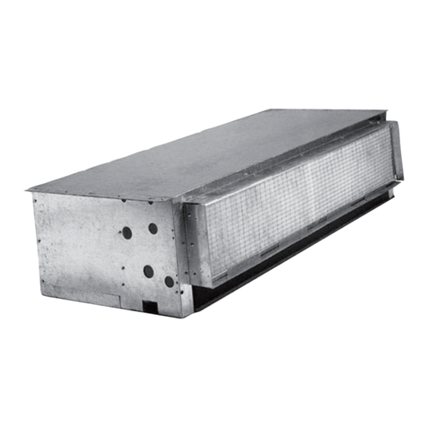
Lennox EDA User manual

Humiditrol Enhance Dehumidication Accessory
(EDA) Units
Installation, Setup and User Guide
506064-02 4/2019
Supersedes 506064-01
2019©Lennox Industries Inc.
Dallas, Texas, USA
NOTE - EDA is not applicable to variable-capacity outdoor units!

2
2.7. Using Humiditrol Comfort Adjust ........................................................................19
2.8.DehumidicationRequirements .........................................................................20
3. Enabling Thermostats for Humiditrol.................................. 20
3.1.CS7500ResidentialThermostat ........................................................................20
3.2.iComfortE30andS30Thermostats...................................................................21
3.3.iComfortM30Thermostat ..................................................................................21
4. Modes of Operation .............................................................. 21
4.1.DehumidicationMode(CoolingON).................................................................21
4.2.CoolingMode(DehumidicationOFF)...............................................................22
4.3.HeatingMode(HeatPumpApplications) ...........................................................22
5. Air Resistance ....................................................................... 22
6. Thermostat Demand Signal.................................................. 23
7. Checklist ................................................................................ 24
Table of Contents
1. General..................................................................................... 2
1.1.ShippingandPackingList....................................................................................2
1.2.AdditionalPartsRequired ....................................................................................3
1.3.Introduction ..........................................................................................................3
1.3.1. ComfortSense®7500Thermostat ........................................................................ 3
1.3.2. iComfort®FamilyofThermostats ......................................................................... 3
1.3.3. OperationOverview .............................................................................................. 3
1.3.4. OperationNotes .................................................................................................... 4
1.4.WiringDiagramLocater .......................................................................................4
1.5.DecisionTree .......................................................................................................5
1.6. Unit Dimensions...................................................................................................6
1.7.InstallationConguration......................................................................................7
1.7.1. HorizontalandUp-ow.......................................................................................... 7
1.7.2. Down-ow ............................................................................................................. 8
1.8.ComponentFunctions ........................................................................................10
1.8.1. ChargeCompensator.......................................................................................... 10
1.8.2. Check/FlowRestrictor ......................................................................................... 10
1.8.3. ValveAssembly ................................................................................................... 10
2. Installation ............................................................................. 11
2.1.Information ......................................................................................................... 11
2.1.1. Refrigeration.........................................................................................................11
2.1.2. ReleasingAirCharge ...........................................................................................11
2.1.3. RefrigerantLineConnections...............................................................................11
2.2.ElectricalWiring ................................................................................................. 11
2.3.HumiditrolInstallationandCheckoutFlowChart ...............................................17
2.4.LeakTesting,Evacuating,Charging...................................................................18
2.4.1. 3-WayDivertingValveOperation ........................................................................ 18
2.4.2. LeakTesting,Evacuating,Charging.................................................................... 19
2.5.InsulatingandSealingtheUnit ..........................................................................19
2.6.OtherSystemComponents................................................................................19
2.6.1. BlowerControl..................................................................................................... 19
2.6.2. ThermostatandSensor....................................................................................... 19
1. General
1.1. Shipping and Packing List
Table 1. Packing List
Quantity Description
1 Humiditrol®EnhancedDehumidicationAccessory(EDA),EDA-024B(94M41),
EDA-036C(94M42)orEDA-060D(94M43)
1Bagassembly(includescheck/owrestrictorforuseonHumiditrolcoil,andHumid-
itrolEDAnoticationlabel).
1Outdoorfanrelayandwiringharness(usedinselectapplications.Refertosystem
wiringdiagramspages18to21forapplicableapplications).
1InstallationInstruction
1Warranty(W-772-L8-04)

3
1.2. Additional Parts Required
Separately-ordered components are restricted to those listed in the Product
Specicationsandthepricebook
Table 2. Additional Parts
Quantity Description
Application
specic
OutdoorTemperatureSensor(X2658)
75VA24VACindoorunittransformer(12P61)isrequiredwhentheHumiditrolunitis
installedwithatwo-stageheatpumpsystem.
HumiditrolInsulationandPipingKit(referto“Figure1.DecisionTree”onpage
5).
HumiditrolZoningAccessory(39W67).Requiredwheninstallinginsystemwith
HarmonyIIIzoningsystem.
HumiditroliscompatiblewiththefollowingLennoxthermostats:
Table 3. Compatible Lennox Thermostats
Description
ComfortSense®7500thermostat(13H14)
iComfort®E30SmartThermostat(15S64)
iComfort®M30Thermostat(15Z69)
iComfort®S30UltraSmartThermostat(12U67)
IMPORTANT
TheapprovedapplicationfortheHumiditrolunitisrestrictedtothoselistedinthe
ProductSpecicationsandpricebook
NOTE: Due to Lennox’ ongoing commitment to quality, features and options are
subject to change without notice and without incurring liability. Improper
installation, adjustment, alteration, service or maintenance can cause
property damage or personal injury. Installation and service must be
performed by a qualied installer and servicing agency.
1.3. Introduction
Humiditrol® is designed for installation with a Lennox HFC-410A split-system
outdoor unit and an air handler or a furnace with a variable speed blower. It is
designedforindoorinstallationsonlyineitherup-oworhorizontalairdischarge
applications.
NOTE: Humiditrol is not compatible with variable-capacity outdoor units!
• HumiditrolisforuseonlyonHFC-410Asystemswiththermalexpansionvalve
installed.
• Prior to installation, study the decision tree (see “Figure 1. Decision Tree” on
page 5) to conrm that all application requirements for Humiditrol installation
aremet.
• Lowambientpressureswitchtypecontroloptioncanbeappliedtothistypeof
system down to 30ºF. For low ambient kit part numbers, refer to the Product
Specicationsaccessoriessection.
NOTE: The low ambient control option (down to 0ºF) is not compatible with
Humiditrol.
Beforebeginninginstallation,besuretheHVACsystemcomponentsarecompatible
with the Humiditrol. See “Figure 1. Decision Tree” on page 5 for the system
decision tree that describes compatible components of the system. One of the
followingthermostatsisrequiredfortheHumiditrolsystem:
1.3.1. ComfortSense®7500 Thermostat
NOTE: When wiring the thermostat into the system, be sure these requirements
are met:
• Minimum18gaugethermostatwireisused.
• Maximumthermostatwirerunlengthdoesnotexceed300feet(90m).
• Totalloadfromanythermostatconnectionislessthan1amp.
1.3.2. iComfort®Family of Thermostats
NOTE: When wiring the thermostat into the system, be sure these requirements
are met:
• Minimum18gaugethermostatwireisused.
• Maximumthermostatwirerunlengthdoesnotexceed1500feet(455m)
• Totalloadfromanythermostatconnectionislessthan1amp.
1.3.3. Operation Overview
NOTE: These instructions are intended as a general guide and do not supersede
local codes in any way. Consult authorities having jurisdiction before
installation.
• The Humiditrol unit operates to dehumidify, as required, when ambient
temperaturesarebelow95ºF.
• However,whentemperaturesreach95ºF,coolinganddehumidicationdemands
are both serviced by increased cooling system run-time and does not use
Humiditrol.
• Neither the CS7500 or any of the iComfort family of thermostats will activate
Humiditrolwhentheambienttemperatureisatorabove95ºF.
• Priortosystemcheckout,considertheoutdoorambienttemperaturesincethe
Humiditrolwillnotoperateabove95ºF.
• Plantestingtobeconductedwhentemperaturesarebetween65ºFand95ºFto
ensureproperHumiditrolsetupandcheckoutoperation.
• Humiditrolremovesmoisturefromtheindoorairatagreaterratethancooling
alone. On a call for dehumidication, the indoor blower is slowed down, the
outdoorfan is operated atalowerspeed, and thecompressor isupstagedto
high-stageoperation(two-stageunits).Theindoorcoolingcoilnowoperatesasa

4
lowertemperatureremovingadditionalhumidity.Atthesametime,theHumiditrol
three-wayvalvesrepositionthemselvesandtheHumiditrolcoilbecomesactive.
Thisallowscondenserheattowarmtheindoorairtoavoidexcessiveovercooling
ofthehome.Duringcoolingonly(noHumiditroloperation)theHumiditrolcoilis
inactive.
• TheHumiditrolcoilisaddedtoanHVACsystemdownstreamoftheindoorcoil.
Indehumidicationmode,thecoilbecomesanextensionoftheoutdoorcoiland
injectsheatintotheindoorairstream.
• Thisdehumidicationmodeallowssignicantlyimprovedcontrolofthehumidity
intheconditionedspacewithlesschanceofovercoolingthespace.
• The assembly includes a set of 3-way diverting valves which will either route
refrigerantthroughtheHumiditrolcoil,orcausetherefrigeranttobypassthethat
coil,dependingonthemodeofoperation.
1.3.4. Operation Notes
• Dehumidicationwillnotoccurwhentheoutdoortemperatureisatorabove95ºF
orindoortemperatureisatorbelow65ºF.
• Whenoperatingincooling(orheatpumpheating)mode,alltemperaturesand
pressureswillbeasinanormalsystem.
• WhenthethermostatisinHumiditrolmode,andafteracoolingdemandhasbeen
satisedbutadehumidicationdemandpersists,andtheroomtemperatureis
within the MIN, MID, MAX parameters described in Using Humiditrol Comfort
Adjust(see“2.7.UsingHumiditrolComfortAdjust”onpage19),theairhandlers
willoperateatreducedairowwiththecompressorathighspeed.
• When the unit is in the dehumidication mode, the thermostat will display
“dehumidifyoranicon”onthehomescreen.
IMPORTANT
TheCleanAirActof1990banstheintentionalventingofallrefrigerants(CFC,
HFC,andHCFC)asofJuly1,1992.Approvedmethodsofrecovery,recycling
or reclaiming must be followed. Fines and/or incarceration may be levied for
non-compliance
WARNING
Improperinstallation,adjustment,alteration,serviceormaintenancecancause
propertydamage,personalinjuryorlossoflife.
Installation and service must be performed by a licensed professional HVAC
installer(orequivalent)oraserviceagency.
WARNING
Riskofexplosionorre.
Cancauseinjuryordeath.
Recoverallrefrigeranttorelievepressurebeforeopeningthesystem.
1.4. Wiring Diagram Locater
Table 4. Wiring Diagram Locater
Thermostat Indoor Unit Control Outdoor Unit Control Wiring Diagram
ComfortSense 7500 or
iComfort M30 Non-communicating Non-communicating
“Figure11.CS7500
orM30withanyNon-
CommunicatingIndoor
andOutdoorUnits”on
page12.
ComfortSense 7500 or
iComfort M30 Non-communicating
Lennox
Communicating
wiredas24VAC
Conventional
“Figure12.CS7500
orM30withNon-
CommunicatingIndoor
andCommunicating
OutdoorUnits
WiredforNon-
Communicating”on
page13.
ComfortSense 7500 or
iComfort M30
Lennox
Communicatingwired
asnon-communicating
Lennox
Communicatingwired
asnon-communicating
“Figure13.CS7500
orM30with
CommunicatingIndoor
andOutdoorUnits
withBothWiredNon-
Communicating”on
page14.
iComfort E30
Lennox
Communicatingwired
asnon-communicating
Lennox
Communicatingwired
asnon-communicating
“Figure14.E30
withbothIndoor
andOutdoor
Communicating
UnitsWiredforNon-
Communicating”on
page15.
iComfort S30 Lennox
Communicating
Lennox
Communicating
“Figure15.S30
WiredSystemfor
Communicating”on
page16.

5
1.5. Decision Tree
Upflow/Horizontal
NOTE − AIR HANDLER REQUIRES
FIELD-FABRICATED TRANSITION
BETWEEN BLOWER OUTLET AND
EDA COIL.
[If
furnace]
Select
indoor
coil
MUST BE
TXV ONLY
Select EDA
Zoning
application?
START
Must use one of
these variable speed
indoor units:
CBA25UHV, CBA27UHE, CBA38MV, CBX27UH,
CBWMV, EL296UHV, EL296DFV,
ML296UHV, ML296DFV
SL280UHV, SL280UHNV, SL280DFV,
SL297UHNV, SLP98UHV, SLP98DFV ONLY!!
*Must use one of
these outdoor units:
YES NO YES
Is
selection a
certified AHRI rated
system (https://www.
ahridirectory.org)
Downflow
NOTE - REQUIRES ADDITIONAL
FIELD-FABRICATED SUPPORT
FRAME AND TRANSITION; SEE
INSTALLATION SUPPLEMENT,
“Installing Humiditrol®Unit in
Downflow Configuration”.
Upflow/
Horizontal Downflow
How
installed
?
YES
INSTALL SYSTEM
Order Humiditrol®Zoning
Accessory (HZA) Kit (39W67)
REFER TO INSTALLATION INSTRUCTION,
“Installing The Humiditrol®Enhanced
Dehumidification Accessory (EDA) In A
Harmony III™ Zoning System Using The
Humiditrol®Zoning Accessory”
Application
Not Approved
DO NOT
INSTALL!
NO
Harmony
III™ Zoning
System
?
YES
Select Piping Kit
NO
Select different equipment
X = PREFERRED MATCH-UP
A = ALLOWED FOR PHYSICAL MATCH-UP TO INDOOR COIL
Capacity
HUMIDITROL®EDA MODEL
EDA-024B
(94M41)
EDA-036C
(94M42)
EDA-060D
(94M43)
-018 XA
-024 XA
-030 XA
-036 XA
-042 X
-048 X
-060 X
*Not applicable to variable-capacity outdoor units!
13ACXN, 14ACX, 16ACX, EL16XC1, ML14XC1,
SL18XC1, SSB, TSAH4, TSAS4, XC13N, XC14,
XC16, XC21 ONLY!
14HPX, 16HPX, EL15XP1, EL16XP1, ML14XP1,
ML16XP1, SL18XP1, SPB, TPAH4, XP14,
XP16, XP21 ONLY!
Capacity Type Outdoor Unit Model Piping Kit
018 AC 13ACXN, 14ACX, EL16XC1, ML14XC1, XC13N, XC14 98M62
HP 14HPX, EL15XP1, EL16XP1, ML14XP1, ML16XP1, XP14 98M22
024 AC 13ACXN, 14ACX, EL16XC1, ML14XC1, SL18XC1, XC13N, XC14, XC21 98M62
16ACX, XC16 98M22
XC21 94M44
HP 16HPX, SL18XP1, XP16, XP21 94M44
14HPX, EL15XP1, ML14XP1, XP14 98M62
EL16XP1, ML16XP1 98M22
030 AC 13ACXN, 14ACX, 16ACX, EL16XC1, ML14XC1, SL18XC1, XC13N, XC14 98M62
HP 14HPX, EL15XP1, ML14XP1 98M62
EL16XP1, ML16XP1, SL18XP1 98M22
036 AC 13ACXN, 14ACX, 16ACX, EL16XC1, ML14XC1, SL18XC1, SSB, TSAH4, TSAS4,
XC13N, XC14, XC16
98M62
XC21 94M44
HP 14HPX, 16HPX, EL15XP1, ML14XP1, SPB, TPAH4, XP14, XP16, XP21 94M44
EL16XP1, ML16XP1, SL18XP1 98M22
042 AC 13ACXN, 14ACX, EL16XC1, ML14XC1, SL18XC1, TSAH4, TSAS4, XC13N, XC14 98M62
HP 14HPX, TPAH4, XP14 94M44
EL15XP1, EL16XP1, ML14XP1, ML16XP1, SL18XP1 98M22
048 AC 13ACXN, 14ACX, 16ACX, EL16XC1, ML14XC1, SL18XC1, SSB, TSAH4, TSAS4,
XC13N, XC14, XC16
98M62
XC21 94M44
HP XP21 94M44
14HPX, 16HPX, EL15XP1, EL16XP1, ML14XP1, ML16XP1, SL18XP1, SPB,
TPAH4, XP14, XP16
98M22
060 AC 13ACXN, TSAS4, XC13N 98M62
14ACX, 16ACX, EL16XC1, ML14XC1, SL18XC1, SSB, TSAH4, XC14, XC16 98M22
XC21 94M44
HP 16HPX, EL15XP1, EL16XP1, ML14XP1, ML16XP1, SPB, XP16 98M22
14HPX, SL18XP1, TPAH4, XP14, XP21 94M44
iComfort®
E30, M30 or
ComfortSense®
7500?
NO
YES
Figure 1. Decision Tree
6
1.6. Unit Dimensions
EDA Model Dimensions - Inches (mm)
11/16
(17)
20-3/4
(527)
D
OUTLET
AIR
OPENING
11/16
(17)
11/16 (17)
11/16 (17)
Dimension EDA-024B EDA-036C EDA-060D
A17-1/2 (445)21 (533)24-1/2 (622)
B12-1/4 (311) 12-1/4 (311) 14 (356)
C16-1/8 (422)19-5/8 (498) 23-1/8 (587)
D16-1/8 (422)19‐5/8 (498) 23-1/8 (587)
E1-3/8 (35)3-1/8 (79) 4-7/8 (124)
F3-1/8 (79)4-7/8 (124)6-5/8 (168)
G3 (76)3-1/4 (83) 4-3/4 (121)
1-7/16 (37)
20-1/8
(511)
22-1/4
(565)
11/16 (17)
GNINEPORIATELNIGNINEPORIATELNI
9-1/2
(241)
11/16 (17)
C
B
A
E
G
F1-3/4
(44)
11/16 (17)
1
(25)
2-1/2
(64)
Check/Flow Restrictor
to Vapor Line Te e
Liquid Line
From Outdoor
Unit
Liquid Line to
Indoor TXV
Electrical
Inlet
To Charge Compensator
side connection
AIR FLOW
Figure 2. Unit Dimensions

7
1.7. Installation Conguration
1.7.1. Horizontal and Up-ow
AIR FLOW
AIR FLOW
UP‐FLOW FURNACE
UP‐FLOW AIR HANDLER
EDA-024B: 12-1/2”
EDA-036C: 12-1/2”
EDA-060D: 14”
Varies by indoor
coil model; see
LENNOX
Product
Specifications.
Varies by air
handler model;
see LENNOX
Product
Specifications for
dimensions.
TYPICAL HORIZONTAL
POSITION (Furnace
Shown)
HUMIDITROL
UNIT
FURNACE
INDOOR
COIL
12” (min.)
NOTES:
1. Transition is required for all air handlers; dimension width and depth is
dependent upon the air handler and the Humiditrol model used.
2. Transition is required between indoor coil and 5-ton Humiditrol unit when
used with a small profile furnace.
Alternate installation position information - The Humiditrol coil is not posi-
tion sensitive as long as the correct air flow direction through the coil is
maintained. See Unit Dimensions drawing on page 3 for correct air flow.
TYPICAL UP-FLOW
POSITION (Furnace
Shown)
(TRANSITION
See Note 2)
TRANSITION
(See Note 1)
Varies by
furnace model;
see LENNOX
Product
Specifications for
dimensions.
Figure 3. Installation Arrangements (Horizontal and Up-ow)

8
1.7.2. Down-ow
Thisaccessoryisdesignedforindoorinstallationsineitherup-oworhorizontalairdischargeapplications,however,theunitwillfunctioninthedown-owconguration,
providedtheinstructionscontainedhereinarefollowed.
HUMIDITROL
UNIT
Furnace Configuration
INDOOR
COIL UNIT
INSULATED
TRANSITION
FIELD
CONSTRUCTED
SUPPORT
STAND
Air Handler Configuration
INSULATED
TRANSITION
FIELD
CONSTRUCTED
SUPPORT
STAND
HUMIDITROL
UNIT
Figure 4. Typical Down-ow Congurations for both Air Handler and Gas Furnace

9
EDA−036C: 12−1/2" (318 mm)
EDA−060D: 14" (356 mm)
RETURN AIR PLENUM
FURNACE
FIELD-CONSTRUCTED
SUPPORT STAND
INDOOR COIL UNIT
(INSULATED TRANSITION
HUMIDITROL
UNIT
6" (152 mm) Min.
NOTE −The weight of the indoor coil
and furnace MUST be supported by the
field−contructed support stand − NOT by
transition and Humiditrol coil
VARIES BY INDOOR COIL
MODEL; SEE LENNOX
PRODUCT SPECIFICATION
40 (1016 mm)
Figure 5. Typical Down-ow Furnace
Typical Downflow Air Handler
RETURN AIR PLENUM
AIR HANDLER
FIELD-CONSTRUCTED
SUPPORT STAND
(INSULATED TRANSITION
HUMIDITROL
UNIT
NOTE − The weight of the air handler
MUST be supported by the
field−contructed support stand − NOT by
transition and Humiditrol coil
EDA−036C: 12−1/2" (318 mm)
EDA−060D: 14" (356 mm)
6" (152 mm) Min.
VARIES BY AIR HANDLER
MODEL; SEE LENNOX
PRODUCT SPECIFICATION
FOR DIMENSIONS.
Figure 6. Typical Down-ow Air Handler
Field construct the brackets.
CAUTION! When determining where holes in
the units are to be located and the length of
screws to be used, be sure internal
components will not be jeopardized nor
damaged during assembly.
NOTE − Coil weight must not rest on
transition.
Using the field-constructed brackets, assemble
EDA, transition, and indoor coil, fastening the
brackets to the coil and Humiditrol units with
field−supplied screws.
Move assembled lower package into position (for
example, in the a/c closet).
If location permits, and for better stability, fasten
rear support stand bracket to a wall.
Install and fasten return air plenum to the top
of the unit and secure to wall(s); this will en-
sure the assembly does not tilt forward.
Maneuver furnace into closet, on top
of the coil and between the brackets.
ASSEMBLED HUMIDITROL,
INDOOR COIL AND
TRANSITION
FURNACE
PLENUM
Study the installation site carefully before beginning
installation. These instructions are intended to show a
typical application. Because most sites are different, use
this information as a general guide, making adjustments
if and when necessary, observing all cautions and notes,
and following appropriate ordinances and regulations.
Figure 7. Typical Down-ow Furnace Installation
Field construct the brackets.
CAUTION! When determining where holes in
the units will be located and the length of
screws to be used, be sure internal
components will not be jeopardized nor
damaged during assembly.
NOTE − Air handler weight must not rest on
transition.
Using the field-constructed brackets, assemble the
Humiditrol and transition. If the height of the
opening permits, assemble the air handler as well.
PLENUM
Install and fasten return air plenum to the
top of the unit and secure to wall(s); this
will ensure the assembly does not tilt for-
ward.
If the opening’s height will not accomodate
the entire assembly, move the bottom part
in first, then the air handler. Until it is prop-
erly fastened, be sure to support the weight
of the air handler so that it does not rest on
the transition.
If location permits, and for better stability,
fasten rear support stand bracket to a wall.
Study the installation site carefully before beginning
installation. These instructions are intended to show a
typical application. Because most sites are different, use
this information as a general guide, making adjustments
if and when necessary, observing all cautions and notes,
and following appropriate ordinances and regulations.
CUTAWAY OF CLOSET
DOOR
OPENING
MOVE TOP OF
AIR HANDLER IN
THEN UP
...THEN ROTATE
BOTTOM END
INTO CLOSET
AIR HANDLER
Figure 8. Typical Down-ow Furnace Installation

10
1.8. Component Functions
1.8.1. Charge Compensator
The charge compensator included in the Installation and Piping kit as shown in
“Figure 17. Typical Installation (Horizontal Air Handler Shown)” on page 18
servestomaintaintheproperamountofrefrigerantcirculatingincertainsystems.
(Some systems do not require a charge compensator, but do require a similar
Installation and Piping kit to connect into the system [see Product Specications]).
The charge compensator stores excess refrigerant when the Humiditrol coil is
active(dehumidifying)andreturnsittothesystemduringnormalcoolingorheating
operations.WhentheHumiditrolcoilisactive,lesschargeisrequiredtoobtainthe
properamountofsub-coolingbecauseoftheadditionalcoilsurfaceandthecooler
airwhichpassesovertheHumiditrolcoil.
1.8.2. Check/Flow Restrictor
The check function of the check/ow restrictor (shown in Figure 9) prevents
refrigerant from owing into the inactive components during times when the
Humiditrolcoilisinactive.Theowrestrictorcontrolstherateofreturnofchargeto
thesystemfromthechargecompensatorandtheHumiditrolcoilwhenthesystem
changesfrom”Humiditrolcoilactive”to”Humiditrolcoilinactive.”
1.8.3. Valve Assembly
The rst valve of the diverting valve assembly (gure 10, E) directs the ow of
refrigeranttoeitherbypasstheHumiditrolcoil(Humiditrolcoilisinactive)orpass
throughtheHumiditrolcoil(Humiditrolcoilisactive).Thesecondvalve(gure10F)
directstheowofrefrigerantbacktotheliquidlinewhentherstvalve(E)allows
owthroughtheHumiditrolcoil.WhentheHumiditrolcoilisinactive,thesecond
valve(F)providesaventpathtothesuctionline,drainingtheHumiditrolcoiland
chargecompensatorofliquidrefrigerant.
O-RING SEALS
CHECK/FLOW
RESTRICTOR
CHECK/FLOW
RESTRICTOR
“FLOATS IN
CHATLEFF
CONNECTOR
GREATER
PRESSURE
EDA
UNIT
GREATER
PRESSURE
EDA
UNIT
FROM
VAPOR
LINE
TEE
FROM
VAPOR
LINE
TEE
Figure 9. Check/Flow Restrictor Operation
EDA-024B
D060-ADE
C630-ADE
3-WAY DIVERTING VALVE ASSEMBLY
HUMIDITROL COIL
3-WAY DIVERTING VALVE ASSEMBLY
A- Liquid Line From Outdoor Unit
B- Liquid Line to Indoor TXV
C- Check/Flow Restrictor to VaporLine Te e
AB CD
HUMIDITROL COIL
HUMIDITROL COIL
D- To Charge Compensator side connection (1/4” line must be brazed closed on systems that do not
require the installation of a charge compensator)
E- HUMIDITROL inactive mode - bypasses the HUMIDITROL HUMIDITROL active mode - allows
refrigerant flow through HUMIDITROL
F- HUMIDITROL inactive mode - vent path to suction line; EDA active mode - directs refrigerant flow back to
liquid line.
EF
FE
3-WAY DIVERTING VALVE ASSEMBLY
EF
AB CD
AB CD
Figure 10. Humiditrol Unit Parts Arrangement

11
2. InstallatIon
2.1. Information
WARNING
Riskofpropertydamage,injury,ordeath.
Installation, adjustments, alterations, service and maintenance must be per-
formedbyalicensedprofessionalservicetechnician(orequivalent).
CAUTION
Physicalcontactwith metaledgesandcornerswhileapplying excessiveforce
orrapidmotioncanresultinpersonalinjury.Beawareof,andusecautionwhen
workingnearbytheseareasduringinstallationorwhileservicingthisequipment.
CAUTION
TheHumiditrolcoilisshippedfromthefactorypressurizedwithdryair.Pierce
aholeinthecoil’srubberplugvaporlinesealtorelievethepressurebeforere-
movingtheseals.
2.1.1. Refrigeration
All Humiditrol coils are shipped with a combination check/ow restrictor. The
restrictor is provided in the bag assembly and must be installed. Refer to the
appropriate high and/or low side installation instructions for information on the
appropriatelinesets.RefertoLennoxRefrigerantPipingguide(Corp.9351-L9)for
propersize,type,andapplicationofeld-fabricatedlines.
2.1.2. Releasing Air Charge
NOTE: Humiditrol units are shipped from the factory with dry air as a holding
charge.
1. Ensurethatthecoilisvoidofpressure.
2. Removetherubberplugfromthelines.
3. Ifthere is nopressurewhen the plugsarepierced, check theunitfor leaks
beforecontinuingwiththeinstallation.
2.1.3. Refrigerant Line Connections
When connecting lines, be careful to avoid damaging the 3-way diverting valve
accesspanel.PlaceawetragagainstthepipingplateandaroundtheHumiditrol
unit line connections.A wet rag heat shield must be in place during brazing to
guardagainstdamagetothepaint.
2.2. Electrical Wiring
Reviewthediagramsbeforeinstallationtoensureallnecessarycomponentsare
onhandattimeofinstallation.
ConnecttheHumiditrolunitwiththeindoorandoutdoorunits,andtothethermostat.
BesurethattheoutdoorsensorisinstalledandconnectedtotheComfortSense
7500 thermostat’s outdoor sensor terminal block or that discharge air and/or
outdoor air sensors are connected to the iComfort indoor unit. The table below
eachwiringdiagramshowstherequirementsforcontrolwiring.
TheiComfortthermostatcanusetheoutdoorsensorfactorysuppliedandconnected
in iComfort outdoor units.

12
NUMBER OF WIRES REQUIRED—Indoor unit to: Thermostat to:
System type Humiditrol®EDACS7500 and iComfort
M30
Outdoor Unit Outdoor Air Sensor
1 stage AC
3
7* 3
2
2 stage AC 8* 4
1 stage HP 8* 5
2 stage HP 9* 6
*Includes conductor for 2-stage heat
B4
FAN
Blue
Yellow
Black
K1
FIRST,
CUT YELLOW WIRE HERE. *OUTDOOR RELAY —
NOT REQUIRED WITH
SINGLE‐SPEED
OUTDOOR FAN
Purple
Yellow
Yellow
2
SECOND,
REWIRE YELLOW WIRE AS SHOWN
75
CS7500 and iComort
M30
OUTDOOR
SENSOR
(X2658)
K1
XP19-024 UNITS COME FACTORY WIRED
FOR LOW OUTDOOR FAN SPEED ONLY.
HIGH SPEED Y2 (BLUE WIRE) IS NOT
CONNECTED. BE SURE TO CONNECT
BLUE Y2 WIRE TO TERMINAL OF
OUTDOOR RELAY.
Y1—Y2 JUMPER - ONLY REMOVE IF
2-STAGE COOLING
DS—Y1 JUMPER - MUST BE REMOVED
FOR HUMIDITROL OPERATION
HEAT PUMP APPLICATIONS ONLY -
REMOVE R—O JUMPER.
Purple
Black
OUTDOOR UNIT
DEFROST BOARD (HP)
YELLOW
BROWN
RED
BLUE
BLACK
OUTDOOR UNIT
CONTROL WIRES (AC)
WIRE
NUTS
INDOOR
UNIT
24 VOLT
TERMINAL
STRIP
GREY
RED
EDA VALVE
ACTUATOR
EDA RELAY
BLACK
VIOLET
ORANGE
EDA VALVE
ACTUATOR
EDA RELAY
RED
Use Wire nuts
LATER MODEL VALVE
ACTUATOR
EARLIER
MODEL VALVE
ACTUATOR
1N4005 DIODE (shrink wrapped -
diode is concealed in the wire.)
L1
Humiditrol
Humiditrol
Figure 11. CS7500 or M30 with any Non-Communicating Indoor and Outdoor Units

13
NUMBER OF WIRES REQUIRED—Indoor unit to: Thermostat to:
System Type Humiditrol EDA CS7500 and iComfort
M30 Outdoor Unit Outdoor Air Sensor
1-stage AC
3
7 4
2
2-stage AC 8 5
1-stage HP 9 6
2-stage HP 10 7)
DS—R (W1) JUMPER - MUST BE CUT FOR
HUMIDITROL OPERATION. SEE W1 JUMPER DETAIL.
DS—R TRACE ON A175 - MUST BE CUT FOR
HUMIDITROL OPERATION. SEE TRACE CUT DETAIL.
DS TO R ON A92 - ON-BOARD LINK MUST BE CUT FOR
DEHUMIDIFICATION.
DS—Y1 JUMPER - MUST BE REMOVED FOR
HUMIDITROL OPERATION
HEAT PUMP APPLICATIONS ONLY - REMOVE R—O
JUMPER.
(2-STAGE ONLY) FOR HUMIDITROL OPERATION (EDA),
CONNECT FIELD PROVIDED WIRE FROM DS ON A92
TO DS ON A175.
OUTDOOR
SENSOR
(X2658)
INDOOR UNIT
24 VOLT
TERMINAL
STRIP
Operation sequence for
dehumidification
1. REMOVE 24 VOLTS FROM
DH AND/OR DS
2. THERMOSTAT CYCLES
OUTDOOR UNITS TO Y2
3. INDOOR AND OUTDOOR
FAN SPEEDS REDUCED
Trace cut for
Humiditrol (EDA)
application
Trace intact
CS7500 and iComfort
M30
OUTDOOR UNITS (A175) - WIRE EITHER CONTROL IDENTICALLY
CURRENT CONTROL EARLY CONTROL
GREY
RED
EDA VALVE
ACTUATOR
EDA RELAY
BLACK
VIOLET
ORANGE
EDA VALVE
ACTUATOR
EDA RELAY
RED
SEE TRACE CUT DETAIL.
SEE W1 JUMPER DETAIL.
Clip W1 Jumper for
Humiditrol (EDA)
application
LATER MODEL VALVE
ACTUATOR
EARLIER
MODEL VALVE
ACTUATOR
1N4005 DIODE (shrink wrapped -
diode is concealed in the wire.)
L1
Humiditrol
Figure 12. CS7500 or M30 with Non-Communicating Indoor and Communicating Outdoor Units Wired for Non-Communicating

14
NUMBER OF WIRES REQUIRED—Indoor unit to: Air Sensors (Optional)
System Type Humiditrol EDA Outdoor unit Outdoor Discharge
1-stage AC
3
8 4
2 2
2-stage AC 10 5
1-stage HP 8 6
2-stage HP 10 7
Lennox Communicating
FURNACE (IFC) OR
AIR HANDLER (AHC)
Clip W1 Jumper for
Humiditrol (EDA)
application
Operation sequence for
dehumidification
1. REMOVE 24 VOLTS FROM DH AND/OR DS
2. THERMOSTAT CYCLES OUTDOOR UNITS TO
Y2
3. INDOOR AND OUTDOOR FAN SPEEDS
REDUCED
OUTDOOR
SENSOR
(X2658)
CHARGE
DOOR
Air Sensors
(optional)
Trace cut for
Humiditrol (EDA)
application
Trace intact
OUTDOOR UNITS (A175) - WIRE EITHER CONTROL IDENTICALLY
CURRENT CONTROL EARLY CONTROL
DS—R TRACE - MUST BE CUT FOR
HUMIDITROL OPERATION. SEE TRACE CUT
DETAIL
DS—R (W1) JUMPER - MUST BE CUT FOR
HUMIDITROL OPERATION. SEE W1 JUMPER
DETAIL.
CS7500 and iComfort
M30
GREY
RED
EDA VALVE
ACTUATOR
EDA RELAY
1N4005 DIODE (shrink wrapped -
diode is concealed in the wire.)
BLACK
VIOLET
ORANGE
EDA VALVE
ACTUATOR
EDA RELAY
RED
SEE TRACE CUT DETAIL.
SEE W1 JUMPER DETAIL.
LATER MODEL VALVE
ACTUATOR
EARLIER
MODEL VALVE
ACTUATOR
L1
Humiditrol
CS7500 and iComfort
M30
Figure 13. CS7500 or M30 with Communicating Indoor and Outdoor Units with Both Wired Non-Communicating

15
NUMBER OF WIRES REQUIRED—Indoor unit to: Air Sensors (Optional)
System Type Humiditrol EDA Outdoor unit Outdoor Discharge
1-stage AC
3
8 4
2 2
2-stage AC 10 5
1-stage HP 8 6
2-stage HP 10 7
Lennox Communicating
FURNACE (IFC) OR
AIR HANDLER (AHC)
Clip W1 Jumper for
Humiditrol (EDA)
application
Operation sequence for
dehumidification
1. REMOVE 24 VOLTS FROM DH AND/OR DS
2. THERMOSTAT CYCLES OUTDOOR UNITS TO
Y2
3. INDOOR AND OUTDOOR FAN SPEEDS
REDUCED
CHARGE
DOOR
Air Sensors
(optional)
Trace cut for
Humiditrol (EDA)
application
Trace intact
OUTDOOR UNITS (A175) - WIRE EITHER CONTROL IDENTICALLY
CURRENT CONTROL EARLY CONTROL
DS—R TRACE - MUST BE CUT FOR
HUMIDITROL OPERATION. SEE TRACE CUT
DETAIL
DS—R (W1) JUMPER - MUST BE CUT FOR
HUMIDITROL OPERATION. SEE W1 JUMPER
DETAIL.
CS7500 and iComfort
M30
GREY
RED
EDA VALVE
ACTUATOR
EDA RELAY
1N4005 DIODE (shrink wrapped -
diode is concealed in the wire.)
BLACK
VIOLET
ORANGE
EDA VALVE
ACTUATOR
EDA RELAY
RED
SEE TRACE CUT DETAIL.
SEE W1 JUMPER DETAIL.
LATER MODEL VALVE
ACTUATOR
EARLIER
MODEL VALVE
ACTUATOR
L1
Humiditrol
iComfort®
E30 Smart
Hub)
iComfort E30
Figure 14. E30 with both Indoor and Outdoor Communicating Units Wired for Non-Communicating

16
NUMBER OF WIRES REQUIRED—Indoor unit to: Air Sensors (Optional)
System Type Humiditrol EDA
iComfort S30 Outdoor unit Discharge Outdoor
1-stage AC
3 4 4 2 2
2-stage AC
1-stage HP
2-stage HP
CHARGE
DOOR
Air Sensors
(optional)
Lennox Communicating
FURNACE (IFC) OR
AIR HANDLER (AHC)
iComfort®
S30 Smart
Hub)
Operation sequence for
dehumidification
1. REMOVE 24 VOLTS FROM DH AND/OR
DS
2. THERMOSTAT CYCLES OUTDOOR
UNITS TO Y2
3. INDOOR AND OUTDOOR FAN SPEEDS
REDUCED
MAXIMUM TOTAL LENGTH OF ALL
CONNECTIONS ON THE RSBUS IS LIMITED
TO 1500FT.
WIRE GAUGE OF RSBUS WIRE IS 18.
OUTDOOR UNITS (A175) - WIRE EITHER CONTROL IDENTICALLY
CURRENT CONTROL EARLY CONTROL
GREY
RED
EDA VALVE
ACTUATOR
EDA RELAY
BLACK
VIOLET
ORANGE
EDA VALVE
ACTUATOR
EDA RELAY
RED
IN COMMUNICATING SYSTEM, THERMOSTAT DS
INPUT IS NOT USED AND DEHUMIDIFICATION IS
CONTROLLED VIA DEHUMIDIFICATION RELAY THAT
CONTROLS 24VAC OUTPUT ON DH TERMINAL.
1N4005 DIODE (shrink wrapped -
diode is concealed in the wire.)
EARLIER
MODEL VALVE
ACTUATOR
LATER MODEL VALVE
ACTUATOR
L1
Humiditrol
Humiditrol
Figure 15. S30 Wired System for Communicating

17
2.3. Humiditrol Installation and Checkout Flow Chart
FollowingtheproceduresreferenceinthissectionwheninstallingtheHumiditrol
andassociatedcomponents.
Table 5. Required Parts for Specic Applications
Required Parts Application
NOTE: After conrming that all required parts per this table are available, proceed with installation.
Any non-zoning
AC or Single
Stage HP
Non-Zoning
Two Stage HP
AC or HP and
Harmony III Zoning
Humiditrol Unit with check/ow
restrictor and label Yes Yes Yes
Thermostats: ComfortSense® 7500,
iComfort®E30, M30 and S30 Smart
Thermostat
All All CS7500orM30(see
note)
Outdoor Sensor (X2658, for non-
communicating out door units) Yes Yes Yes
Insulation and Piping Kit Yes Yes Yes
75VA Transformer (12P61) —Yes Yes(iftwo-stageHP)
Humiditrol Zoning Accessory
(39W67) — — Yes
NOTE: We recommend that for an all full communicating systems that the iHarmony®zoning system
is used.
NOTE - Lennox communicating systems support iHarmony zoning sytem only. Cannot use Harmony III in
total communicating system.
MAKE WIRING CONNECTIONS
INSTALL “EDA” LABEL ON
OUTDOOR UNIT
POWER UP THE INDOOR UNIT
SEMBLY IS SET TO “COOLING”
POSITION
ENABLE HUMIDITROL ON ROOM
THERMOSTAT
SET THERMOSTAT FOR
MAXIMUM COOLING
OPEN REFRIGERANT VALVES
TURN OUTDOOR UNIT MAIN
POWER ON
CHECK CHARGE AND CHARGE
AS NEEDED
Installation Process
YES
NO
ENSURE ALL POWER IS OFF
INSTALL EDA UNIT IN DUCT
SYSTEM
INSTALL THE
PENSATOR (IF REQUIRED) IN
CONVENIENT LOCATION
MAKE ALL REFRIGERATION
CONNECTIONS, BEING SURE
TO INSTALL THE CHECK/FLOW
RESTRICTOR
LEAK CHECK THE SYSTEM
WITH 3-WAY VALVE assembly
SET TO “EVACUATE”
INSULATE ALL REFRIGERANT
LINES
EVACUATE THE SYSTEM AS
DESCRIBED IN THE OUTDOOR
UNIT INSTALLATION
INSTRUCTIONS
INSTALL OUTDOOR SENSOR
IS
THE
OUTDOOR
TEMPERAT URE
BELOW
95ºF
?
SET COOLING SETPOINT ON ROOM THERMOSTAT
TO 2 DEGREES ABOVE INDOOR TEMPERATURE
(OUTDOOR UNIT WILL TURN OFF)
NOTE -A Humiditrol®EDA-equipped system is allowed
to operate and cool room temperature below cooling set
point when trying to satisfy a persisting humidity set
point.
DEHUMIDIFICAT ION
IS DE-ACTIVATED;
CHECK FOR
CORRECT
OPERATION AT A
TIME WHEN
AMBIENT
TEMPERATURE IS
BELOW 95ºF.
OUTDOOR UNIT:
COMPRESSOR IN HIGH STAGE;
FAN IN LOWEST SPEED;
EDA:
3-WAY VALVE ASSEMBLY TO “DEHUMIDIFICATION”
POSITION
INDOOR UNIT:
FAN IN DEHUMIDIFICATION SPEED
CHECK THE TEMPERATURE DIFFERENCE
ACROSS THE EDA COIL AND THE LIQUID LINE
TEMPERATURES
Check Dehumidification Operation
SET DEHUMIDIFICATION SETPOINT TO 5% BELOW
CURRENT ROOM RELATIVE HUMIDITY
Figure 16. Humiditrol Installation and Checkout Flow Chart

18
INDOOR UNIT
OUTDOOR UNIT
AIR-FLOW
Vapor
Line
LIQUID
LINE
LIQUID LINE
DOOR UNIT
LIQUID LINE TO
INDOOR TXV
TXV
VAPOR
LINE
LIQUID
LINE
MUST BE INSULATED
SULATED
HUMIDITROL
CHARGE
COMPENSATOR
7/8 X 7/8 X
3/8 TEE
UPFLOW POSITION
ELECTRICAL INLET
TO CHARGE
COMPENSATOR
SIDE CONNECTION
(SOME
APPLICATIONS)
CHECK/FLOW
RESTRICTOR TO
VAPOR LINE TEE
LIQUID LINE TO
INDOOR TXV
LIQUID LINE FROM
OUTDOOR UNIT
AIR
FLOW
VAPOR LINE FROM
INDOOR COIL
EDA UNIT
1/4” TUBING
CONNECTION -
MUST BE ON
BOTTOM OF
COMPENSATOR
IMPORTANT!
RESTRICTOR MUST BE INSERTED WITH O-RING
END OF RESTRICTOR TOWARD EDA UNIT FITTING.
TORQUE CHATLEFF CONNECTION TO 20 FT. LBS.
CHECK/FLOW
RESTRICTOR
AND O-RING
FITTING IN EDA UNIT
TEFLON SEAL
USE REDUCER(S)
FROM CHARGE
COMPENSATOR KIT
(WHEN REQUIRED)
12 ft. max.
LENGTH BETWEEN CHARGE
COMPENSATOR AND EDA USING
1/4” LINE PROVIDED IN CHARGE
COMPENSATOR KIT
12 ft. max.
DROP TO CHARGE
COMPENSATOR
CHARGE
COMPENSATOR
7/8 X 7/8 X
3/8 TEE
LIQUID LINE FROM
OUTDOOR UNIT
VAPOR LINE
FROM
OUTDOOR
UNIT
1/4” TUBING
CONNECTION - MUST
BE AT LOWEST POINT
OF THE COMPENSATOR
ELECTRICAL
INLET
TO CHARGE
COMPENSATOR SIDE
CONNECTION
CHECK/FLOW
RESTRICTOR TO
VAPOR LINE TEE
LIQUID LINE TO
INDOOR TXV
VAPOR
LINE
FROM
INDOOR
COIL
Charge
Compensator
Details
USE REDUCER(S) FROM
CHARGE COMPENSATOR
KIT (WHEN REQUIRED)
12 FT MAX. LENGTH TO CHECK/FLOW
RESTRICTOR ON EDA
USE REDUCER(S)
FROM CHARGE
COMPENSATOR KIT
(WHEN REQUIRED)
Check/Flow‐
Restrictor
Details
1/4” PORT MUST
BE BRAZED
CLOSED
NO CHARGE
COMPENSATOR
OR 1/4” LINE
VAPOR LINE FROM
OUTDOOR UNIT
System without
compensator
NOTE 1 - (Any upflow or horizontal application) The physical distance between the evaporator coil
and the EDA unit can be extended so long as all of the evaporator coil air flow also flows through
the EDA coil and the 12 foot line length limitations are met.
See NOTE 1 near
bottom of page.
12 FT MAX. LENGTH
TO CHECK/FLOW
RESTRICTOR ON EDA
TYPICAL HORIZONTAL POSITION INSTALLATION
Figure 17. Typical Installation (Horizontal Air Handler Shown)
2.4. Leak Testing, Evacuating, Charging
IMPORTANT
The 3-way diverting valve actuator shaft pinch bolt (see “Figure 19. Setting
3-WayDivertingValveto Evacuate Position” onpage19)isfactorysetandis
nottobeadjusted.
IMPORTANT
Priortostartingtheoutdoorunitforcharging,besurethe3-wayvalveisener-
gizedandinthe“cooling”(forward)position(seeFigure18).
2.4.1. 3-Way Diverting Valve Operation
NOTE: During system operation, the 3-way valve requires 24-volt power to drive
between cooling and dehumidication.
The3-waydivertingvalve is actually twovalves connectedby a commonshaft,
designedtoopenonevalvewhileclosingtheother,andvice-versa.Forevacuating
(withpoweroff),thedivertingvalvecanberepositionedusingitsactuatorlever,a
longpinchboltthathasbeenfactory-settoaprecisepointonthecommonshaft.Do
notloosen(unscrew)thepinchbolt.Shouldthepinchboltbecomeloose,carefully
followthenoteinthefollowingguretopositionandtightenit.
NOTE - Actuator shaft pinchbolt is
come loose, use pliers to grip the
shaft where shown (1) and rotate
the shaft (in direction of the black
arrow) until the pin stops (inset
shows pin and stops). Press the
red button (2) in the direction of the
white arrow and move the lever (3)
to the forward position and tighten
pinchbolt to 60 in‐lbs torque.
STOP
PIN
SHAFT
STOP
2
3
1
Figure 18. Re-Aligning Pinch Bolt

19
2.4.2. Leak Testing, Evacuating, Charging
1. Setthe3-waydivertingvalveactuatorshafttothecenter(evacuate)positionfor
leaktestingandevacuationasillustratedinthefollowinggure.IMPORTANT!
TheactuatorshaftmustbesetasdescribedtoallowtheHumiditroltoevacuate
morequickly.
2. Refertoinstructionsprovidedwiththeoutdoorunitforleaktesting,evacuating
andchargingprocedures
3. VerylittlechargeisrequiredfortheadditionalvolumeoftheHumiditrolunit.
Wheninnormalcooling,thecomponentswillallbeoccupiedbyvaporthathas
verylittleweight.Atmost(dependingonthemodel)anadditional1/4poundof
refrigerantmayberequired.
4. When shifting from dehumidify mode to cooling, or vice-versa, wait at least
10minutesforthesystemtoreachstableoperatingpressurebeforechecking
temperaturesandpressures,oradjustingrefrigerantcharge.
NOTE: Prior to starting the outdoor unit for charging, set the thermostat to call for
cooling (dehumidication OFF). It will take about 90 seconds for the 3-way
diverting valve to energize and shift to the cooling position. To ensure
that the 3-way diverting valve is energized and in the “cooling” (forward)
position, observe the position of the 3-way diverting valve actuator shaft
pinch bolt in the following gure; if properly shifted, the pinch bolt will be in
the forward position.
1
2
COOLING
(FORWARD)
EVACUATE
(CENTER)
DEHUMIDIFICATION
(REARWARD)
1. PUSH RED TAB IN DIRECTION INDICATED.
2. PUSH ACTUATOR SHAFT DOWN TOWARD THE
CENTER-OF-TRAV EL POSITION
Figure 19. Setting 3-Way Diverting Valve to Evacuate Position
5. The charge must be checked with the system in cooling operation
(dehumidication OFF). After testing and charging as required, set the
thermostattoforceademandfordehumidication.
2.5. Insulating and Sealing the Unit
IMPORTANT
Allpiping,meteringdevices,andconnectionsmustbeinsulatedtopreventmois-
turedamagecausedbysweating.
Sealthe unit sothatwarm air isnotallowedinto the cabinet.This isespecially
importantwhentheunitisinstalledinanunconditionedarea.Makesuretheliquid
lineentrypointsaresealedwitheitherrefrigeranttubeinsulatingmaterialorwith
Permagum.
2.6. Other System Components
2.6.1. Blower Control
When Humiditrol units are to be applied with an indoor unit that has a variable
speedmotor(VSM),thenrefertotheindoorunitinstallationinstructionforsetting
blowerspeed.
2.6.2. Thermostat and Sensor
RefertotheComfortSense7500,iComfortE30,M30orS30ThermostatInstallation
andSetupGuidefornon-communicatinginstallation,wiring,andsetup.
NOTE: Lennox communicating outdoor units have an outdoor sensor installed.
If these units are connected to a Lennox communicating thermostat, an
optional outdoor sensor is not needed.
IMPORTANT
EitheraCS7500oriComfortfamilythermostatalongwithaproperlyconnected
outdoortemperaturesensorarerequiredfortheHumiditrolunittofunctionprop-
erly.
Installtheremotesensorontheoutsideofanorthernwallofthehome,awayfrom
directsunlightorotherheatsourcesthatmayaffectitsabilitytoaccuratelysense
outdoortemperature.
2.7. Using Humiditrol Comfort Adjust
IfHumiditrolisenabledintheinstallersettings,thentheHumiditrolAdjustmentin
theUserSettingsaffectsovercoolingoperation(see“Table6.HumiditrolComfort
Adjust Parameters” on page 20 and “Figure 20. Thermostat Operation with
HumiditrolEnabled”onpage20describetheparametersandillustrateHumiditrol
operationundertypicalsettings).

20
Overcoolingrangesfrom2ºFbelowthecoolingsetpoint(MINsetting)downto2ºF
abovetheheatingsetpoint(MAXsetting).Halfwaybetweenthetwosettingsisthe
MID setting.
Table 6. Humiditrol Comfort Adjust Parameters
Humiditrol Comfort Adjust parameters Indoor temperature is greater than:
Maximumovercooling 2%aboveheatingsetpoint
Midpointovercooling HeatSetpoint+CoolSetpoint
2
Minimumovercooling 2°Fbelowcoolingsetpoint
2.8. Dehumidication Requirements
Humiditrol can only operate when the thermostat is set to COOL orAUTO and
meetstheparametersdescribedinthefollowingtable.Ifthethermostatissetto
HEAT mode, no dehumidication will occur!Thermostat cycles heating ON and
OFFtomaintainheatingsetpoint.
Table 7. Thermostat Operation with Humiditrol Enabled
Thermostat set to COOL mode-
Dehumidication will only occur if:
Thermostat set to AUTO changeover-
Dehumidication will only occur if:
• Outdoorsensoronroomthermostat
installedandsetup
• Dehumidicationenabledoninstaller
settings
• Dehumidicationdemandispresent
• Coolingdemandisnotpresent
• Outdoortemperatureislessthen95ºF
• Indoortemperatureisnotcoolerthan
65ºF
• Outdoorsensoronroomthermostatinstalledand
setup
• Dehumidicationenabledoninstallersettings
• Dehumidicationdemandispresent
• Coolingdemandisnotpresent
• Outdoortemperatureislessthen95ºF
• Indoortemperatureisnotcoolerthan65ºF
• Indoor temperature is not cooler than 2ºF above
heatingsetpoint.
Iftheconditionsabovearemet,24VACis
removedfromtheHumiditrol”D”terminal
andcoolingbegins(Indoorvariablespeed
motorrunsatdehumidicationspeedand
outdoorunitbeginsthecoolingcycle).
CoolingcallshavepriorityoverHumiditrol
calls.
Inthiscase,24VACisremovedfromtheHumiditrol
”D”terminalandcoolingbegins(Indoorvariable
speedmotorrunsatdehumidicationspeedand
outdoorunitbeginsthecoolingcycle).Coolingcalls
havepriorityoverHumiditrolcalls.Humiditrolmode
overcoolingisuseradjustableandisdescribedin
Using Humiditrol Comfort Adjust.
HumiditrolmodeovercoolingisuseradjustableandisdescribedinUsingHumiditrolComfort
Adjust.
NO
Is
indoor
temperature
greater than 2ºF
below cooling set
point
?
Is
indoor temp.
greater than the heat
setpoint plus the cool
setpoint divided by 2?
YES
NO
one or both
is true
neither
is true
Is
there a
dehumidification
demand
?
DEACTIVATE
ALL EQUIPMENT
RUN EQUIPMENT
IN NORMAL
HEATING MODE
RUN EQUIPMENT
IN NORMAL
COOLING MODE
Is
EITHER true:
outdoor temp. > 95ºF;
indoor temp. < 65ºF
?
Humiditrol
Comfort Adjust
setting is:
RUN
HUMIDITROL
START
Is
there a heating
demand
?
YES
NO
YES
Is
there a cooling
demand
?
NO
YES
YES
NO
Is
indoor
temperature
greater than 2ºF
above heating set
point
?
YES
NO
DEACTIVATE
ALL EQUIPMENT
LEGEND:
CSP = Cooling Set Point
HSP = Heating Set Point
Figure 20. Thermostat Operation with Humiditrol Enabled
3. enablInG thermostats for humIdItrol
3.1. CS7500 Residential Thermostat
NOTE - Humiditrol operation requires
use of an outdoor sensor. If sensor is not
connected enable plus Humiditrol selected.
played in the information display.
1.Touch menu option from the
home screen.
2.Touch and hold the settings option on the
menu. This will display the installer settings
confirmation screen. Touch confirm
ue.
installer settings
confirm
<
installer settings must be set
by qualified person.
A selection option under Installer settings > Humidity settings > Dehumidify > Dehumidify mode must be enabled
before
tive humidity (RH). The installer settings include:
Installing Outdoor Sensor
Install the
light or other heat sources that may affect its sensitivity.
NOTE - The outdoor sensor uses standard thermostat wiring; it may be wired using two wires of a multi-wire cable
with a wire run not to exceed 300 feet or 100 meters.
1.Connect outdoor sensor to terminals Tc and To on thermostat.
2.Outdoor sensor also has to be enabled under menu > settings > outdoor sensor = yes or no.
1.NORMAL
2.MAX
3.AUXILIARY DEHUMIDIFIER
4.HUMIDITROL
5.OFF
Figure 21. ComfortSense 7500 Thermostat—Add and Adjust Humiditrol
Table of contents
Other Lennox Fan manuals

Lennox
Lennox KG Series User manual

Lennox
Lennox ARIA EC Series User guide

Lennox
Lennox V8LAC01 User manual

Lennox
Lennox LPVK-110 User manual

Lennox
Lennox EvenHeater ECB29EH User manual

Lennox
Lennox FLATAIR KFC Series User manual

Lennox
Lennox COMFAIR HH Series User guide

Lennox
Lennox ALLEGRA II User manual

Lennox
Lennox V8V33B001-3P User manual

Lennox
Lennox Enlight LGT Series User manual