manuals.online logo
Brands
  1. Home
  2. •
  3. Brands
  4. •
  5. Lennox
  6. •
  7. Heat Pump
  8. •
  9. Lennox LHT Series Owner's manual

Lennox LHT Series Owner's manual

Page 1
LHT
Service Literature 6.5 / 7.5 / 8.5 /10 / 12.5
100087
LHT HEAT PUMP SERIES
WARNING
To prevent serious injury or death:
1- Lock-out/tag-out before performing maintenance.
2- If system power is required (e.g., smoke detector main
tenance), disable power to blower, remove fan belt
where applicable, and ensure all controllers and ther
mostats are set to the “OFF” position before
performing maintenance.
3- Always keep hands, hair, clothing, jewelry, tools, etc.,
away from moving parts.
WARNING
Improper installation, adjustment, alteration, service
or maintenance can cause property damage, person
al injury or loss of life. Installation and service must
be performed by a licensed professional HVAC in
staller or equivalent, service agency, or the gas sup
plier
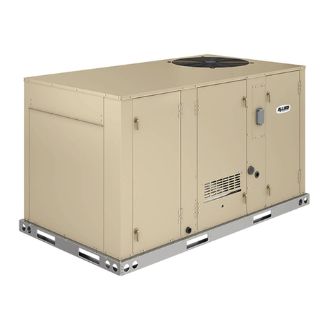
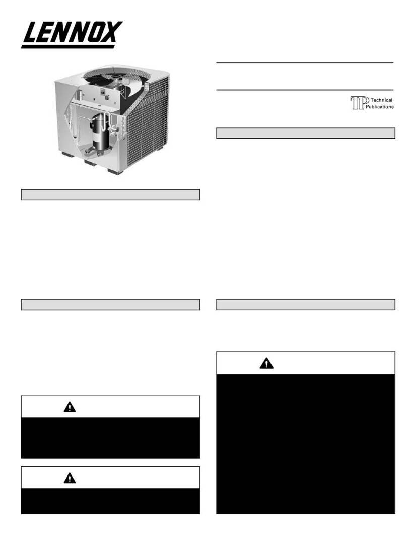
The LHT commercial heat pump is available in 6.5, 7.5, 8.5,
10 and 12.5 ton capacities. The refrigerant systems utilize
two compressors, two reversing valves, two accumulators,
and other parts common to a heat pump. Electric heat oper
ates in single or multiple stages depending on the kW input
size. 7.5kW through 60kW heat sections are available for
the LHT heat pump.
LHT078-150 units are equipped with variable-volume, di
rect drive blowers. These units will provide supply air at
lower speeds when cooling demand is low and increase to
higher speeds when cooling demand is high. Refer to Sup
ply Air Start-Up sections.
LHT units are designed to accept any of several different
energy management thermostat control systems with mini
mum field wiring.
Information contained in this manual is intended for use by
qualified service technicians only. All specifications are
subject to change. Procedures outlined in this manual are
presented as a recommendation only and do not super
sede or replace local or state codes.
If the unit must be lifted for service, rig unit by attaching four
cables to the holes located in the unit base rail (two holes at
each corner). Refer to the installation instructions for the
proper rigging technique.
EE
M
CAUTION
As with any mechanical equipment, contact with
sharp sheet metal edges can result in personal in
jury. Take care while handling this equipment and
wear gloves and protective clothing.
WARNING
Electric shock hazard. Can cause injury
or death. Before attempting to perform
any service or maintenance, turn the
electrical power to unit OFF at discon
nect switch(es). Unit may have multiple
power supplies.
Table of Contents
Options / Accessories 2..........................
Specifications 5.................................
Blower Data 7..................................
Electrical \ Electric Heat Data 10...................
I Unit Components 16............................
II Placement and Installation 28....................
III Start Up 28...................................
IV System Service Checks 29.....................
V Maintenance 31................................
VI Accessories 32................................
VII Wiring Diagrams 37...........................
Page 2
OPTIONS / ACCESSORIES
Item Description Catalog
Number
Unit Model No
078 092 102 122 150
COOLING SYSTEM
Condensate Drain Trap PVC 22H54 XXXXX
Copper 76W27 XXXXX
 21Z07 OX OX OX OX OX
BLOWER - SUPPLY AIR
 ® OOOOO
CABINET
 24C86 OX OX OX
24C87 OX OX
  OOOOO
 51W25 XXXXX
 54W96 OX OX OX OX OX
CONTROLS
 21Z10 OX OX OX OX OX
 CPC Einstein Integration  OOOOO
® 54W27 OX OX OX OX OX
Novar®   OOOOO
 53W67 OX OX OX OX OX
 21Z08 OX OX OX OX OX
 11K76 OX OX OX OX OX
 11K80 OX OX OX OX OX
INDOOR AIR QUALITY
Air Filters
®󰀩

 50W61 OX OX OX OX OX
 52W41 OX OX OX OX OX
 21U41 XXXXX
 Y3063 XXXXX
Indoor Air Quality (CO) Sensors
󰀨 77N39 XXXXX
󰀨 23V86 XXXXX
 87N52 XXXXX
 87N54 XXXXX
CO 85L43 XXXXX
77N3990N43 XXXXX
Needlepoint Bipolar Ionization (NPBI)
 22U15 XXXXX
UVC Germicidal Lamps
1® 21A93 XXXXX
  10H20 XXXXX
 10H21 XXXXX
1




X = Field Installed.

OPTIONS / ACCESSORIES
Item Description Catalog
Number
Unit Model No
078 092 102 122 150
ELECTRICAL
   OOOOO
  OOOOO
  OOOOO
  54W56 OX OX OX OX OX
 54W57 OX OX OX OX OX
  OOOOO


 74M70 OX OX OX OX OX
  OOOOO
 67E01 XXXXX
²   OOOOO
 10C89 XXXXX
ELECTRIC HEAT
  23U73 OX OX OX
 23U74 OX OX OX
 23U75 OX OX OX
  23U76 OX OX OX OX OX
 23U77 OX OX OX OX OX
 23U78 OX OX OX OX OX
  23U79 OX OX OX OX OX
 23U80 OX OX OX OX OX
 23U81 OX OX OX OX OX
  23U82 OX OX OX OX OX
 23U83 OX OX OX OX OX
 23U84 OX OX OX OX OX
  23U85 OX OX OX OX
 23U86 OX OX OX OX
 23U87 OX OX OX OX
  23U88 OX OX
 23U89 OX OX
 23U90 OX OX
1


2



X = Field Installed.
Page 4
OPTIONS / ACCESSORIES
Item Description Catalog
Number
Unit Model No
078 092 102 122 150
ECONOMIZER





20U80 OX OX OX OX OX
Horizontal Barometric Relief Dampers
 53K04 XXXXX
Economizer Controls
󰀨 Order 2 21Z09 OX OX OX OX OX
   OOOOO
 21Z09 OX OX OX OX OX
 13J77 XXXXX
 13J76 XXXXX
   OOOOO
OUTDOOR AIR
Outdoor Air Dampers With Outdoor Air Hood
 14G28 OX OX OX OX OX
 14G29 XXXXX
POWER EXHAUST
  53W44 OX OX OX OX OX
 53W45 OX OX OX OX OX
 53W46 OX OX OX OX OX
ROOF CURBS

 11F54 XXXXX
 11F55 XXXXX
 11F56 XXXXX
 11F57 XXXXX
Adjustable Pitch Curb
 54W50 XXXXX
CEILING DIFFUSERS
  13K61 X X
 13K62 XXX
  13K56 X X
 13K57 XXX
  12X65 X X
 12X66 XXX



X = Field Installed.
Page 5
SPECIFICATIONS 6.5 TON | 7.5 TON | 8.5 TON
General Data Nominal Tonnage 6.5 Ton 7.5 Ton 8.5 Ton
󰀩 High High High
Model Number LHT078H4E LHT092H4E LHT102H4E
Blower Type 

®


®


®
Cooling
Performance
   
1   
 2400 2800 2800
  7.4 8.1
1 12.4 12.1 12.1
1   15.5
   


   
   
Heating
Performance
1   
   
  7.0 
1C.O.P.   
1   
 5.2  
1C.O.P. 2.25 2.25 2.25
Electric Heat Options Available  
Compressor Type (number) 

Outdoor Coil    
   
   
 20 20 20
Outdoor
Coil Fans
   
   
   
   
   
   
Indoor
Coil
 12.8 12.8 12.8
   
 444
 14 14 14
 
 

Indoor
Blower
   
   
Filters  
 
Electrical characteristics 

1
Cooling Ratings
High Temperature Heating Ratings
Low Temperature Heating Ratings

SPECIFICATIONS 10 TON | 12.5 TON
General Data Nominal Tonnage 10 Ton 12.5 Ton
󰀩 High High
Model Number LHT122H4E LHT150H4E
Blower Type 

®


®
Cooling
Performance
  
1  
  4200
  12.4
1 12.1 11.0
1 15.5 
  


  
  
Heating
Performance
1  
  4200
  11.0
1C.O.P.  
1  
 8.5 10.2
1C.O.P. 2.25 2.10
Electric Heat Options Available 
Compressor Type (number) 

Outdoor Coil  40.4 40.4
  
  
 20 20
Outdoor
Coil Fans
  
  
  
  
  
  
Indoor
Coil
 12.8 12.8
  
 4 4
 14 14
 
 

Indoor
Blower
  
  
Filters  
 
Electrical characteristics 

1
Cooling Ratings
High Temperature Heating Ratings
Low Temperature Heating Ratings
Page 7
BLOWER DATA
BLOWER TABLE INCLUDES RESISTANCE FOR BASE UNIT ONLY (NO HEAT SECTION) WITH DRY INDOOR COIL AND AIR
FILTERS IN PLACE.



󰀨


Total
Air Volume
cfm
Total Static Pressure - in. w.g.
0.2 0.4 0.6 0.8 1.0 1.2 1.4
RPM Watts RPM Watts RPM Watts RPM Watts RPM Watts RPM Watts RPM Watts
1750        420 1128 508    704
2000  271    410 1117 488   1255 704  804
2250     1111  1184 577 1247     
2500     1180  1245       1008
2750   1182  1248 715      1011  
    718  827   1444 1024    
 1282 711  827    1044 1521     
  821     1544      1700 
   1517 1081 1571 1221     1725 1700  1875
4000           1801  1847 
4250    1458   1784    1877   
4500 1724 1510 1772  1818 1851       2000 
4750 1811       2254    2587  
5000    2144   2028 2480 2071  2114 2805 2158 
5250  2205     2111       
5500 2070 2428 2112           
5750              
Total
Air Volume
cfm
Total Static Pressure - in. w.g.
1.6 1.8 2.0 2.2 2.4 2.6
RPM Watts RPM Watts RPM Watts RPM Watts RPM Watts RPM Watts
1750    875     1548 1175  
2000   1425   1081 1540     1458
2250  1001 1480 1101       1700 
2500  1117       1700  1752 1810
2750 1547      1705     2004
  1425  1577 1715    1815   
    1787 1778  1828 2110    
 1748    1844       
  2048  2214     2012   
4000      2581   2084   
4250  2475     2111     
4500    2844 2140  2187     
4750 2124  2170         
5000            
5250            
5500            
Page 8
BLOWER DATA
POWER EXHAUST FAN PERFORMANCE
Return Air System Static Pressure Air Volume Exhausted
in. w.g. cfm
0
0.05 
0.10 
0.15 2410
0.20 
0.25 
 1420
 1200
MINIMUM AIR VOLUME REQUIRED FOR USE WITH OPTIONAL ELECTRIC HEAT
Electric Heat kW Minimum cfm
7.5 1750
15 2250
22.5 2250
 2750
45 2750
 
FACTORY INSTALLED OPTIONS/FIELD INSTALLED ACCESSORY AIR RESISTANCE - in. w.g.
Air
Volume
cfm
Wet Indoor Coil Electric
Heat Economizer
Filters Return Air
Adaptor
Plate
078, 092 102, 122, 150 MERV 8 MERV 13 MERV 16
1750 0.04 0.04  0.05 0.01   0.00
2000 0.05 0.05   0.01  0.08 0.00
2250   0.04 0.08 0.01 0.04  0.00
2500 0.07 0.07 0.04 0.11 0.01 0.05 0.10 0.00
2750 0.08 0.08 0.05 0.12 0.02 0.05 0.11 0.00
 0.10    0.02  0.12 0.02
 0.11 0.10  0.15 0.02   0.02
 0.12 0.11  0.15  0.07 0.15 0.04
 0.14   0.15  0.08  0.07
4000 0.15 0.14   0.04 0.08 0.17 
4250 0.17 0.15   0.04   0.11
4500  0.17 0.14 0.22 0.04  0.20 0.12
4750 0.20 0.18 0.17 0.25 0.05 0.10 0.21 
5000 0.22 0.20 0.20   0.10  0.18
5250 0.24 0.22 0.22   0.11 0.24 
5500 0.25  0.25  0.07 0.12 0.25 0.22
5750 0.27 0.25  0.45 0.07 0.12 0.27 0.25
  0.27  0.52 0.08  0.28 0.27

BLOWER DATA
CEILING DIFFUSERS AIR RESISTANCE - in. w.g.
󰀨 FD11 Flush
󰀨
Unit Size Air Volume
cfm 2 Ends Open 1 Side, 2 Ends
Open
All Ends & Sides
Open

2400 0.21 0.18 0.15 0.14
 0.24 0.21 0.18 0.17
2800 0.27 0.24 0.21 0.20
   0.25 0.25
 0.41   
 0.50 0.45  
  0.54 0.48 0.44
   0.57 0.51

  0.28  0.15
 0.40   0.18
4000 0.44   0.21
4200  0.40  0.24
4400 0.54 0.44  0.27
   0.42 
4800    
5000  0.58 0.50 
5200 0.75  0.54 

4200 0.22   0.10
4400 0.28 0.24 0.20 0.12
   0.24 0.15
4800 0.40   
5000    
5200 0.52 0.44  0.27
5400 0.58   
  0.54 0.47 
5800 0.70  0.51 
CEILING DIFFUSER AIR THROW DATA
Model No. Air Volume
1󰀨
RTD11 Step-Down FD11 Flush
cfm ft. ft.


  
2800  
  
  
  


  
  
4000  
4200  
4400  
150

  
5800  
  
  
  
  
1󰀨

Page 10
ELECTRICAL/ELECTRIC HEAT DATA 6.5 TON
Model No. LHT078H4E
1Voltage - 60Hz 208/230V-3ph 460V-3ph 575V-3ph


  7.1 
 105  


 8.5  
 70  27


 2.8 1.4 1.1


 2.4  1
 15 15 20


   
 8.7 4.7 4.1
2


 50 25 20


50 25 20



  21 


42 22 17
ELECTRIC HEAT DATA
Electric Heat Voltage 208V 240V 480V 600V
2



Unit+

7.5 kW 4  70  25
15 kW 4 80  45 
22.5 kW 4 100 110  45
30 kW 4 125 150 70 




Unit+

7.5 kW    25
15 kW  85  
22.5 kW  107 55 
30 kW 118   52
2



Unit+



7.5 kW 70 70  
15 kW   45 
22.5 kW 4 100 110  45
30 kW 4 125 150 70 




Unit+



7.5 kW    
15 kW 81 87 45 
22.5 kW 100   44
30 kW 120   
ELECTRICAL ACCESSORIES
Disconnect 7.5 kW 54W56 54W56 54W56 54W56
15 kW 54W57 54W57 54W56 54W56
22.5 kW 54W57 54W57 54W56 54W56
30 kW 54W57 54W57 54W56 54W56

1
2

4
Page 11
ELECTRICAL/ELECTRIC HEAT DATA 7.5 TON
Model No. LHT092H4E
1Voltage - 60Hz 208/230V-3ph 460V-3ph 575V-3ph


  7.1 
 105  


   4.8
   


 2.8 1.4 1.1


 2.4  1
 15 15 20


   
 8.7 4.7 4.1
2


 50 25 20


  20



 45  17


47 24 18
ELECTRIC HEAT DATA
Electric Heat Voltage 208V 240V 480V 600V
2



Unit+

7.5 kW 70 70  
15 kW   50 
22.5 kW 4 110 125  45
30 kW 4 125 150 70 
45 kW 4 175 200 100 80




Unit+

7.5 kW    
15 kW 84   
22.5 kW  112 57 44
30 kW    
45 kW  180  72
2



Unit+



7.5 kW 70 70 40 
15 kW 4  100 50 40
22.5 kW 4 110 125  45
30 kW 4 125 150 70 
45 kW 4 175 200 100 80




Unit+



7.5 kW  70  27
15 kW   47 
22.5 kW  115 58 45
30 kW 125   54
45 kW    
ELECTRICAL ACCESSORIES
Disconnect 7.5 kW 54W56 54W56 54W56 54W56
15 kW 54W57 54W57 54W56 54W56
22.5 kW 54W57 54W57 54W56 54W56
30 kW 54W57 54W57 54W56 54W56
45 kW N/A N/A 54W57 54W56

1
2

4
Page 12
ELECTRICAL/ELECTRIC HEAT DATA 8.5 TON
Model No. LHT102H4E
1Voltage - 60Hz 208/230V-3ph 460V-3ph 575V-3ph


  7.1 
 105  


  7.8 5.7
 110 52 


 2.8 1.4 1.1


 2.4  1
 15 15 20


   
 8.7 4.7 4.1
2


   20


  20



 48 25 


50  20
ELECTRIC HEAT DATA
Electric Heat Voltage 208V 240V 480V 600V
2



Unit+

7.5 kW 4 70 80 40 
15 kW 4  100 50 40
22.5 kW 4 110 125  50
30 kW 150 150 70 
45 kW 4 175 200 100 80




Unit+

7.5 kW  70  28
15 kW 87  47 
22.5 kW  115  
30 kW   70 55
45 kW    
2



Unit+



7.5 kW 80 80 40 
15 kW 4  100 50 40
22.5 kW 4 110 125  50
30 kW 150 150 80 
45 kW 4 175 200 100 80




Unit+



7.5 kW 70   
15 kW    
22.5 kW  118  47
30 kW 128 140 71 
45 kW  185  74
ELECTRICAL ACCESSORIES
Disconnect 7.5 kW 54W56 54W56 54W56 54W56
15 kW 54W57 54W57 54W56 54W56
22.5 kW 54W57 54W57 54W56 54W56
30 kW 54W57 54W57 54W56 54W56
45 kW N/A N/A 54W57 54W56

1
2

4

ELECTRICAL/ELECTRIC HEAT DATA 10 TON
Model No. LHT122H4E
1Voltage - 60Hz 208/230V-3ph 460V-3ph 575V-3ph


  7.1 5.7
 110 54.7 47.8


  8.2 
   


 2.8 1.4 1.1


 2.4  1
 15 15 20


   
 8.7 4.7 4.1
2


 70  25


80  25



  27 22


 28 
ELECTRIC HEAT DATA
Electric Heat Voltage 208V 240V 480V 600V
2



Unit+

15 kW 4 100 110 50 40
22.5 kW 4 125 150 70 50
30 kW 150 150 80 
45 kW 200 200 100 80
60 kW 4 200 225 100 80




Unit+

15 kW  104  40
22.5 kW 117   
30 kW   72 58
45 kW    
60 kW 184   80
2



Unit+



15 kW 110 110  45
22.5 kW 4 125 150 70 50
30 kW 4 150 175 80 
45 kW 200 200 100 80
60 kW 4 200 225 100 




Unit+



15 kW 100  51 41
22.5 kW 120   50
30 kW  151  
45 kW 178   77
60 kW   100 81
ELECTRICAL ACCESSORIES
Disconnect 15 kW 54W57 54W57 54W56 54W56
22.5 kW 54W57 54W57 54W56 54W56
30 kW 54W57 N/A 54W56 54W56
45 kW N/A N/A 54W57 54W56
60 kW N/A N/A 54W57 54W56

1
2

4
Page 14
ELECTRICAL/ELECTRIC HEAT DATA 12.5 TON
Model No. LHT150H4E
1Voltage - 60Hz 208/230V-3ph 460V-3ph 575V-3ph


  8.5 
   


  10 7.5
   54


 2.8 1.4 1.1


 2.4  1
 15 15 20


   
 8.7 4.7 4.1
2


 80  


80 40 



   24


  25
ELECTRIC HEAT DATA
Electric Heat Voltage 208V 240V 480V 600V
2



Unit+

15 kW 110 110  45
22.5 kW 4 125 150 70 
30 kW 4 150 175 80 
45 kW 200 200 100 80
60 kW 4 200 225 110 




Unit+

15 kW    42
22.5 kW 122   51
30 kW 142 154  
45 kW 181   78
60 kW  208  81
2



Unit+



15 kW 4 110 125  45
22.5 kW 4 125 150 70 
30 kW 4 150 175 80 70
45 kW 4 200 225 100 80
60 kW 4 200 225 110 




Unit+



15 kW 105 111 54 
22.5 kW 124   52
30 kW 144  77 
45 kW  201  
60 kW  210 104 82
ELECTRICAL ACCESSORIES
Disconnect 15 kW 54W57 54W57 54W56 54W56
22.5 kW 54W57 54W57 54W56 54W56
30 kW 54W57 N/A 54W56 54W56
45 kW N/A N/A 54W57 54W56
60 kW N/A N/A 54W57 54W57

1
2

4
Page 15
LHT078-150 PARTS ARRANGEMENT
FIGURE 1
UNIT
CONTROLLER
INDOOR
COIL
OUTDOOR FANS
(3 ON 122 & 150)
OUTDOOR
COIL
COMPRESSORS CONDENSATE
DRAIN
FILTERS
(FOUR - 20 X 25 X 2”)
ECONOMIZER
(OPTIONAL)
BLOWER
(DIRECT DRIVE)
ELECTRIC HEAT
(OPTIONAL)
WIRELESS
BOARD
WIFI
ANTENNA
REVERSING
VALVE
LHT078-150 CONTROL BOX
FIGURE 2
W4
A55
K65
T3
T1
T18
TB13
K1
K2
S117
SHADED AREA IS A HINGED PANEL IN FRONT OF
CONTROLS AREA (OPTIONAL A173 LOCATION)
Page 16
I-UNIT COMPONENTS
The LHT unit parts arrangement are shown in figure 1. All
L1, L2, and L3 wiring is color coded; L1 is red, L2 is yellow,
and L3 is blue. See wiring diagrams in the back of this
manual for complete call out of components per LHT unit.
All 7.5 through 12.5 ton units are configure to order units
(CTO).
A-Control Box Components
ELECTROSTATIC DISCHARGE (ESD)
Precautions and Procedures
CAUTION
Electrostatic discharge can affect elec
tronic components. Take precautions
to neutralize electrostatic charge by
touching your hand and tools to metal
prior to handling the control.
LHT control box components are shown in figure 2. The
control box is located in the upper portion of the com
pressor compartment.
1-Disconnect Switch S48 or Circuit Breaker
CB10 (field installed)
LHT units may be equipped with an optional disconnect
switch S48 or circuit breaker CB10. S48 and CB10 are tog
gle switches, which can be used by the service technician
to disconnect power to the unit.
2-Compressor Contactor K1 & K2
All compressor contactors are three‐pole‐double‐break
contactors with a 24VAC coil. In all LHT units, K1 and K2
energize compressors B1 and B2 respectively in response
to first, second or third stage cooling demands. The auxil
iary N.C. contacts are opened to disable the crankcase
heaters when compressor is energized.
3-Transformer T1
All LHT series units use a single line voltage to 24VAC
transformer mounted in the control box. Transformer sup
plies power to control circuits in the unit. The transformer is
rated at 92VA and is protected by a 6 amp circuit breaker
(CB8). The 208/230 (Y) voltage transformers use two pri
mary voltage taps as
shown in figure 3, while
460 (G) and 575 (J) volt
age transformers use a
single primary voltage
tap.
4-Transformer T18
T18 is a single line voltage to 24VAC transformer used in all
LHT units. T18 is rated at 70VAC and is protected by a 3.5
amp circuit breaker (CB18).
5-Power Exhaust Relay K65 (PED units)
Power exhaust relay K65 is a N.O. DPDT relay with a
24VAC coil. K65 is used in all LHT units equipped with the
optional power exhaust dampers. K65 is energized by the
economizer control panel (A6), after the economizer
dampers reach 50% open (adjustable on control A6).
When K65 closes, the exhaust fan B10 is energized.
6-Terminal Block (TB13)
TB13 terminal block distributes line voltage power to the
line voltage items in the unit.
FIGURE 3
RED
230 VOLTS
208 VOLTS
PRIMARY
SECONDARY
208/230V TRANSFORMER
Page 17
PLUMBING COMPONENTS
FIGURE 4
Condenser Coil
Evaporator Coil
Compressor 1
Compressor 2
Reversing Valve
Reversing Valve
LHT078-102
LHT122-150 Condenser Coil
Evaporator Coil
Reversing Valve
Compressor 2 Compressor 1
Accumulators
Page 18
B-Cooling Components
LHT units use independent cooling circuits consisting of
separate compressors, outdoor coils and indoor coil (with 2
separate stages). See figure 4. Units are equipped with two
or three draw-through type condenser fans. and direct-
drive blowers. The blower draws air across the indoor coil
during unit operation.
Cooling may be supplemented by a factory‐or-field‐in
stalled economizer. The indoor coils are slab type and are
stacked. Each indoor coil uses a thermostatic expansion
valve as the primary expansion device. Each indoor coil is
also equipped with enhanced fins and rifled tubing. In all
units, each compressor is protected by a crankcase heater,
high pressure switch and low pressure switch. Additional
protection is provided by by thermistors for low ambient
control and freezing prevention.
1-Compressors B1 and B2
Units use two scroll compressors and two independent
cooling circuits. Compressor capacity may vary from stage
to stage. In all cases, the capacity of each compressor is
added to reach the total capacity of the unit. See “SPECIFI
CATIONS” and “ELECTRICAL DATA” (table of contents)
or compressor nameplate for compressor specifications.
WARNING
Electrical shock hazard. Compressor must be
grounded. Do not operate without protective cover
over terminals. Disconnect power before removing
protective cover. Discharge capacitors before ser
vicing unit. Failure to follow these precautions could
cause electrical shock resulting in injury or death.
Each compressor is energized by a corresponding com
pressor contactor.
NOTE-Refer to the wiring diagram section for specific unit
operation.
IMPORTANT
Some scroll compressors have an internal vacuum
protector that will unload scrolls when suction pres
sure goes below 20 psig. A hissing sound will be
heard when the compressor is running unloaded.
Protector will reset when low pressure in system
rises above 40 psig. DO NOT REPLACE COMPRES
SOR.
2-High Pressure Switches S4, S7
The high pressure switch is an auto‐reset SPST N.C.
switch which opens on a pressure rise. All units are
equipped with this switch. On fin/tube outdoor coils, the
switch is located in the compressor discharge line. On all-
aluminum outdoor coils, the switch is located on the liquid
line in the blower section. Switches are wired in series with
the compressor contactor coil.
On standard and high efficiency units, S4 (first circuit) and
S7 (second circuit) are wired in series with the respective
compressor contactor coils. On ultra high efficiency units,
only S4 is used. S4 is located on the common compressor
discharge line and is wired to both compressor contactors
via the A55 Unit Controller.
When discharge pressure rises to 610 ± 15 psig (4206 ±
103 kPa) (indicating a problem in the system) the switch
opens and the respective compressor is de-energized (the
economizer can continue to operate). When discharge
pressure drops to 475 ± 15 psig (3275 ± 103 kPa) the pres
sure switch will close.
The A55 Unit Controller has a three-strike counter before
locking out. This means the control allows three high pres
sure trips per one thermostat demand. The control can be
reset by breaking and remaking the thermostat demand or
manually resetting the control.
Page 19
3-Reversing Valve L1 and L2
A refrigerant reversing valve with a 24 volt solenoid coil is
used to reverse refrigerant flow during unit operation in all
LHT units. The reversing valve is connected in the vapor
line of the refrigerant circuit. The reversing valve coil is en
ergized during cooling demand and during defrost.
Reversing valve L1 and L2 are controlled by the M4 con
troller in response to cooling demand or by defrost.
4-Defrost Pressure Switch S46 and S104
The defrost pressure switch S46 and S104 are auto‐reset
SPST N.C. pressure switches which open on a pressure
rise. All LHT units are equipped with these switches. The
switches are located on the discharge line. S46 and S104
are wired in series with the CMC1 control board.
5-Low Pressure Switches S87, S88
The low pressure switch is an auto‐reset SPST N.O. switch
(held N.C. by refrigerant pressure) which opens on a pres
sure drop. All units are equipped with this switch. The
switch is located in the compressor suction line.
S87 (compressor one) and S88 (compressor two) are
wired to A55 Unit Controller. A55 governs the low pressure
switches by shunting the switches during start up until pres
sure is stabilized. After the shunt period, the control has a
three‐strike counter, during first thermostat demand, be
fore the compressor is locked out. The control is reset by
breaking and remaking the thermostat demand or manual
ly resetting the control.
When suction pressure drops to 25 + 5 psig, (indicating low
pressure), the switch opens and the compressor(s) is(are)
de-energized. The switch automatically resets when pres
sure in the suction line rises to 40 + 5 psig due to many
causes such as refrigerant being added.
When discharge pressure reaches 450 + 10 psig (3102 $
69 kPa) in either circuit (indicating defrost is completed) the
appropriate switch opens. The switches automatically re
set when pressure in the suction line drops to 300 + 20 psig
(2068 $138 kPa).
6-Defrost Temperature Switch S6 and S9
Defrost thermostat switches S6 and S9 have S.P.S.T. N.O.
contacts which close on a temperature fall (initiating de
frost). The switches are located on the expansion valve dis
tributor assembly at the inlet to the outdoor coil. The switch
monitors the outdoor coil suction temperature to determine
when defrost is needed. When the outdoor coil suction tem
perature falls to 35F + 4F (1.7C + 2.2C) the switch clos
es (initiating defrost after minimum run time of 30, 60, or 90
minutes). When the temperature rises to 60F + 5F
(15.6C + 2.8C) the switch opens.
7-Filter Drier (all units)
LHT units have a filter drier located in the liquid line of each
refrigerant circuit at the exit of each condenser coil (outdoor
coil in LHT units). The drier removes contaminants and
moisture from the system.
8-Condenser Fan Motors B4, B5, B21
See specifications section of this manual for specifications
of condenser fans B4 , B5, and B21 (B21 on 122 and 150
units only). All LHT motors are electrically commutated
condenser fan motors (ECM). The ECM motors are wired
directly to 230VAC power but do not operate until a pulse
width modulated (PWM) control signal is sent from M4 con
troller. All outdoor fans will run at the same speed when the
appropriate PWM signal is received. The fans may be re
moved for servicing and cleaning by removing the fan
grilles.
9-Crankcase Heaters HR1, HR2
Heater HR1 is installed around compressor B1 and heater
HR2 is installed around compressor B2. Crankcase heater
wattage varies by compressor manufacturer.
10-Temperature Sensors RT46, RT47, RT48
& RT49
Units are equipped with four factory-installed thermistors
(RT46 / RT49) located on different points on the refrigerant
circuit.
The thermistors provide the Unit Controller with constant
temperature readings of four specific locations on the re
frigeration circuit. These temperatures are used as feed
back in certain modes of unit operation.
Each thermistor must be specifically placed for proper unit
operation and to initiate valid alarms. See figure 5 and fig
ure 6 proper locations.
Page 20
LHT078, 092, 102, 122, 150
INDOOR COIL
RT46, RT47
DETAILS NOT TO SCALE
BLUE
RT47
YELLOW
RT46
22J06
22J06
FIGURE 5

Other manuals for LHT Series

1

This manual suits for next models

5

Other Lennox Heat Pump manuals

Lennox Signature XP19-024 User manual

Lennox

Lennox Signature XP19-024 User manual

Lennox HP21 User manual

Lennox

Lennox HP21 User manual

Lennox ML16XP1 Series Installation and operation manual

Lennox

Lennox ML16XP1 Series Installation and operation manual

Lennox XP14 Installation and operation manual

Lennox

Lennox XP14 Installation and operation manual

Lennox XC15 Series User manual

Lennox

Lennox XC15 Series User manual

Lennox XP14 User manual

Lennox

Lennox XP14 User manual

Lennox XP16 Installation and operation manual

Lennox

Lennox XP16 Installation and operation manual

Lennox ZHA092 User manual

Lennox

Lennox ZHA092 User manual

Lennox Allied Air 4SHP18LT Series User manual

Lennox

Lennox Allied Air 4SHP18LT Series User manual

Lennox Elite series User manual

Lennox

Lennox Elite series User manual

Lennox Elite XP14-018-230 User manual

Lennox

Lennox Elite XP14-018-230 User manual
Lennox HP27 SERIES User manual

Lennox

Lennox HP27 SERIES User manual

Lennox HS20-211 Setup guide

Lennox

Lennox HS20-211 Setup guide

Lennox TPA036H4N4 User manual

Lennox

Lennox TPA036H4N4 User manual

Lennox HP29 Series Installation and operation manual
Lennox

Lennox HP29 Series Installation and operation manual
Lennox 13HPX User manual

Lennox

Lennox 13HPX User manual

Lennox XP19 User manual

Lennox

Lennox XP19 User manual

Lennox XPG15 Series User manual

Lennox

Lennox XPG15 Series User manual

Lennox T?CLASS TPA S4 User manual

Lennox

Lennox T?CLASS TPA S4 User manual

Lennox FCM 85 User manual

Lennox

Lennox FCM 85 User manual

Lennox HPXA16 series Installation and operation manual

Lennox

Lennox HPXA16 series Installation and operation manual

Lennox G21 Series User manual

Lennox

Lennox G21 Series User manual

Lennox Elite XP16-024-230 User manual

Lennox

Lennox Elite XP16-024-230 User manual

Lennox MS8 SERIES User manual

Lennox

Lennox MS8 SERIES User manual

Popular Heat Pump manuals by other brands

Rheem RJNL-A036CK installation instructions

Rheem

Rheem RJNL-A036CK installation instructions

Bryant 575J 16 Series Installation, Start-Up and Service Instructions

Bryant

Bryant 575J 16 Series Installation, Start-Up and Service Instructions

LG THERMA V HM141MR installation manual

LG

LG THERMA V HM141MR installation manual

Viessmann VITOCAL 300-A Installation and service instructions

Viessmann

Viessmann VITOCAL 300-A Installation and service instructions

Carrier 38ZS/ZF Installation, operation and maintenance instructions

Carrier

Carrier 38ZS/ZF Installation, operation and maintenance instructions

Dimplex LI 22HS Installation and operating instructions

Dimplex

Dimplex LI 22HS Installation and operating instructions

Daikin RXYQ96PYDN Service manual

Daikin

Daikin RXYQ96PYDN Service manual

Toshiba RBM-Y1121FUPE installation manual

Toshiba

Toshiba RBM-Y1121FUPE installation manual

EMI DFPH093 (FHP12-SHC09) specification

EMI

EMI DFPH093 (FHP12-SHC09) specification

Norsup PX Series Original manual

Norsup

Norsup PX Series Original manual

Mitsubishi Electric PEH-P8YE Technical & service manual

Mitsubishi Electric

Mitsubishi Electric PEH-P8YE Technical & service manual

Tecnoclima BESST Series TECHNICAL INFORMATION ASSEMBLY, USE AND MAINTENANCE INSTRUCTIONS

Tecnoclima

Tecnoclima BESST Series TECHNICAL INFORMATION ASSEMBLY, USE AND MAINTENANCE INSTRUCTIONS

Carrier CRPWREXH030A01 installation instructions

Carrier

Carrier CRPWREXH030A01 installation instructions

Mitsubishi Electric SEZ-KD09NA4.TH product manual

Mitsubishi Electric

Mitsubishi Electric SEZ-KD09NA4.TH product manual

International Refrigeration Products MSM30H46ZI Installation and maintenance manual

International Refrigeration Products

International Refrigeration Products MSM30H46ZI Installation and maintenance manual

Interline Eco-3 instruction manual

Interline

Interline Eco-3 instruction manual

Daikin VRV 5 RXYA8A7Y1B Installation and operation manual

Daikin

Daikin VRV 5 RXYA8A7Y1B Installation and operation manual

AIREDALE CUS Series Installation & maintenance

AIREDALE

AIREDALE CUS Series Installation & maintenance

manuals.online logo
manuals.online logoBrands
  • About & Mission
  • Contact us
  • Privacy Policy
  • Terms and Conditions

Copyright 2025 Manuals.Online. All Rights Reserved.