manuals.online logo
Brands
  1. Home
  2. •
  3. Brands
  4. •
  5. Lennox
  6. •
  7. Heat Pump
  8. •
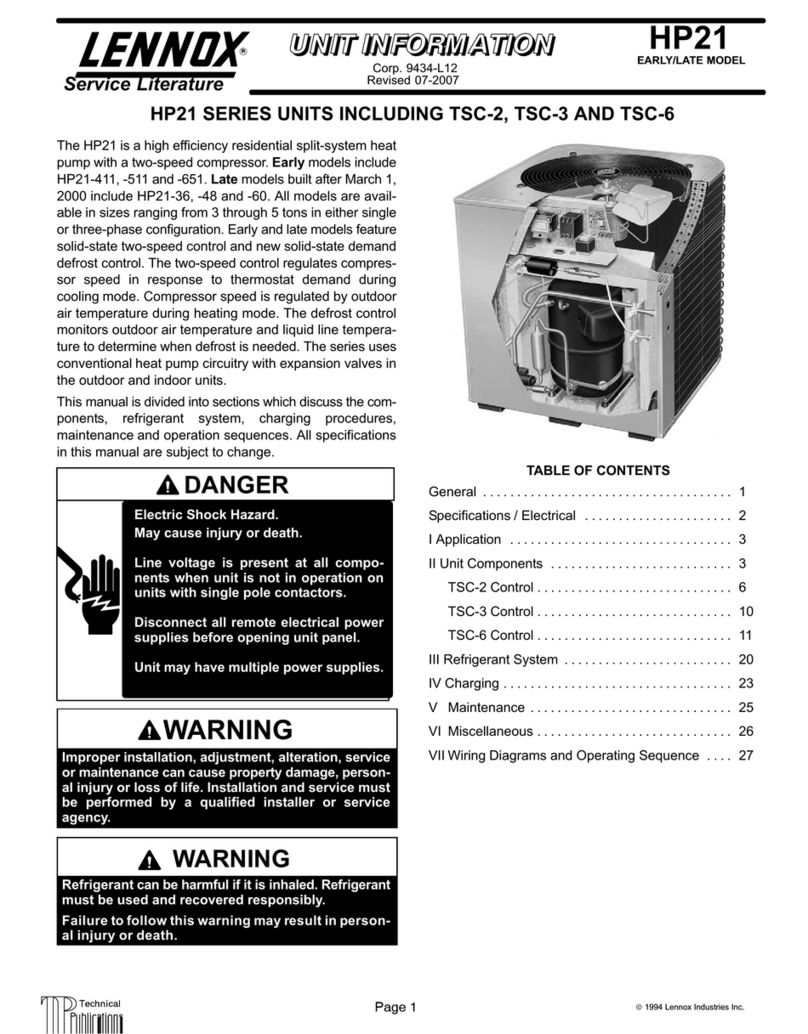
  9. Lennox XP14 User manual

Lennox XP14 User manual

Other manuals for XP14

3

This manual suits for next models

7

Other Lennox Heat Pump manuals

Lennox (2/4)SH13 User manual

Lennox

Lennox (2/4)SH13 User manual

Lennox EL16XP1 Series Installation and operation manual

Lennox

Lennox EL16XP1 Series Installation and operation manual

Lennox XP13 User manual

Lennox

Lennox XP13 User manual

Lennox LGA Series Installation and operation manual

Lennox

Lennox LGA Series Installation and operation manual

Lennox Elite XP13-018-230 User manual

Lennox

Lennox Elite XP13-018-230 User manual

Lennox Merit 10HPB Series User manual

Lennox

Lennox Merit 10HPB Series User manual

Lennox HPXA16 series Installation and operation manual

Lennox

Lennox HPXA16 series Installation and operation manual

Lennox KHA SERIES User manual

Lennox

Lennox KHA SERIES User manual

Lennox SL280UHNV Series Installation and operation manual

Lennox

Lennox SL280UHNV Series Installation and operation manual

Lennox ZHA092 User manual

Lennox

Lennox ZHA092 User manual

Lennox Elite XP14-018-230 User manual

Lennox

Lennox Elite XP14-018-230 User manual

Lennox 12CHP060 User manual

Lennox

Lennox 12CHP060 User manual
Lennox VPB H4-3P Series Installation instructions

Lennox

Lennox VPB H4-3P Series Installation instructions

Lennox NEOSYS NAC 200 User guide

Lennox

Lennox NEOSYS NAC 200 User guide

Lennox HS40 Series User manual

Lennox

Lennox HS40 Series User manual

Lennox LRP16G User manual

Lennox

Lennox LRP16G User manual

Lennox HP29 Series Installation and operation manual
Lennox

Lennox HP29 Series Installation and operation manual

Lennox Allied Air Enterprises BHP16L User manual

Lennox

Lennox Allied Air Enterprises BHP16L User manual

Lennox HP23 Series User manual

Lennox

Lennox HP23 Series User manual

Lennox 16ACX Series Installation and operation manual

Lennox

Lennox 16ACX Series Installation and operation manual

Lennox SPB036H4 User manual

Lennox

Lennox SPB036H4 User manual

Lennox 4HP14 User manual

Lennox

Lennox 4HP14 User manual

Lennox 12HPB Series User manual

Lennox

Lennox 12HPB Series User manual

Lennox XP17 User manual

Lennox

Lennox XP17 User manual

Popular Heat Pump manuals by other brands

Daikin RXL12QMVJU Service manual

Daikin

Daikin RXL12QMVJU Service manual

AIREDALE BluCube CUR092V16-1CO-0 Installation and maintenance manual

AIREDALE

AIREDALE BluCube CUR092V16-1CO-0 Installation and maintenance manual

Calyenty RBH 125 Customer's manual

Calyenty

Calyenty RBH 125 Customer's manual

GRE HPGI50 owner's manual

GRE

GRE HPGI50 owner's manual

Carrier 30XW Installation, operation and maintenance instructions

Carrier

Carrier 30XW Installation, operation and maintenance instructions

Hayward SUMHEAT HP5131DT3 Installation instructions manual

Hayward

Hayward SUMHEAT HP5131DT3 Installation instructions manual

REMKO SQW 400 Electrical wiring

REMKO

REMKO SQW 400 Electrical wiring

Sanyo SAP120FCH Service manual

Sanyo

Sanyo SAP120FCH Service manual

Daikin EHYHBH05AA Operation manual

Daikin

Daikin EHYHBH05AA Operation manual

Panasonic WH-SDF03E3E5 Design handbook

Panasonic

Panasonic WH-SDF03E3E5 Design handbook

Airxcel 45000 Series Installation, operation and maintenance instructions

Airxcel

Airxcel 45000 Series Installation, operation and maintenance instructions

Mitsubishi Electric PUZ-SWM60VAA Service manual

Mitsubishi Electric

Mitsubishi Electric PUZ-SWM60VAA Service manual

Dimplex LI 16I-TUR Installation and operating instruction

Dimplex

Dimplex LI 16I-TUR Installation and operating instruction

Carrier WSHP Open v3 Integration guide

Carrier

Carrier WSHP Open v3 Integration guide

Mitsubishi Electric EHSE-YM9EC Service manual

Mitsubishi Electric

Mitsubishi Electric EHSE-YM9EC Service manual

TGM CTV14CN018A Technical manual

TGM

TGM CTV14CN018A Technical manual

Carrier 38MGQ Series installation instructions

Carrier

Carrier 38MGQ Series installation instructions

Kokido K2O K880BX/EU Owner's manual & installation guide

Kokido

Kokido K2O K880BX/EU Owner's manual & installation guide

manuals.online logo
manuals.online logoBrands
  • About & Mission
  • Contact us
  • Privacy Policy
  • Terms and Conditions

Copyright 2025 Manuals.Online. All Rights Reserved.

ze jv
,1_2008 Lennox industries Inc.
Dallas, Texas, USA
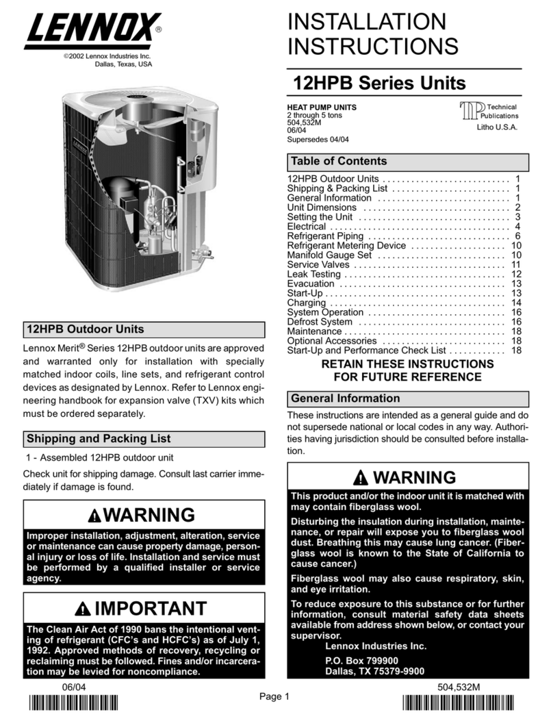
INSTALLATION
INSTRUCTIONS
XP14 Elite ®Series Units
HEAT PUMP UNITS _]_Technical
.ELL1 Publications
505,244M Litho U.S.A.
04108
Supersedes 11/07
RETAIN THESE INSTRUCTIONS
FOR FUTURE REFERENCE
WARNING
CAUTION
AIMPORTANT
AIMPORTANT
XP14 Outdoor Unit ............................ 1
Shipping and Packing List ...................... 1
Unit Dimensions and Parts Arrangement ......... 2
General Information ........................... 3
Setting the Unit ............................... 3
Removing Panels ............................. 5
Electrical ..................................... 6
Refrigerant Piping ............................. 8
Flushing Existing Line Set and Indoor Coil ........ 10
Refrigerant Metering Device .................... 12
Manifold Gauge Set ........................... 13
Service Valves ................................ 13
Leak Testing .................................. 14
Evacuation ................................... 14
Start-Up ...................................... 15
Refrigerant Charge ............................ 15
Check Indoor Airflow before Charging ............ 15
Setup for Checking and Adding Charge .......... 16
Pre-Charge Maintenance Checks ................ 16
Weigh in Charge .............................. 17
Subcooling Charge ............................ 17
Defrost System ............................... 19
Maintenance .................................. 24
User Information .............................. 24
Start-up and Performance Checklist .............. 26
The XP14 outdoor unit uses HFC-410A HFC refrigerant.
This unit must be installed with a matching indoor blower
coil and line set as outlined in the Lennox Engineering
Handbook, Elite® Series XP14 outdoor units are designed
for use in check thermal expansion valve (CTXV) systems
only and are not to be used with other refrigerant flow
control devices. An expansion valve approved for use with
HFC-410A must be ordered separately and installed prior
to operating the unit,
1 - Assembled XP14 outdoor unit
Check the unit components for shipping damage. If you
find any damage, immediately contact the last carrier,
04/08
IIIIIIIIIIIIIIIIIIIIIIIIIIIIIIIIIIIIIIII Page 1 505,244M
IIIIIIIIIIIIIIIIIIIIIIIIIIIIIIIIIIIIIIIIIIIIIIIIII
RUN
DEFROST
REVERSING
SUCTION LINE VALVE HIGH PRESSURE
SWITCH
TOP VIEW
LIQUID LINE
CONNECTION
C
DISCHARGE AIR t
i i
SIDE VIEW
UNIT SUPPORT
FEET _/
_ _ 1(_413)
(
(
LIQUID LINE
CONNECTION
ELECTRICAL
INLETS
VAPOR LINE
/CONNECTION
4-1/4( 4-3/4
108) (121)
f _
t
9-1/2
(2il)
8-1/4
(210)
i_
XP14-018 TO -030 BASE SECTION
FILTER DRIER/
LIQ
CONNECTIONS
PARTS ARRANGEMENT
VAPOR LINE
VAPOR VALVE AND
BAUGE PORT/SUCTION
LINE CONNECTIONS
1
A
1
B "-=
r
2(51)
I I I__._J
1 (25) SIDE VIEW
UNIT SUPPORT _
FEET\
18-7/8 @ @ ®
(429)
8-3/4
(222)
t
3-1/8
(79) _ (781)
-[
26-7/8
(683)
_2
3-3/4
(95)
_4-5/8
(117)
XP14-036 TO -060 BASE WITH
ELONGATED LEGS
Model No. A B C
xP14-018 31 (787) 27 (686) 28 (711)
xP14-024 31 (787) 27 (686) 28 (711)
xP14-030 35 (889) 27 (686) 28 (711)
xP14-036 31 (787) 35 1/2 (902) 39 1/2 (1003)
xP14-042 39 (991) 35 1/2 (902) 39 1/2 (1003)
xP14-048 39 (991) 35 1/2 (902) 39 1/2 (1003)
xP14-060 45 (1143) 35 1/2 (902) 39 1/2 (1003)
Page 2
505244M 04/08
WARNING 4. Locate the unit so prevailing winter winds will not blow
into the coil.
5. Locate unit away from overhanging roof lines which
would allow water or ice to drop on, or in front of, coil
or into unit.
These instructions are intended as a general guide and do
not supersede local codes in any way. Consult authorities
having jurisdiction before installation.
When servicing or repairing HVAC components, ensure
the fasteners are appropriately tightened. Table 1 shows
torque values for fasteners.
Table 1. Torque Requirements
Part Recommended Torque
Service valve cap 8 ft.- lb. 11 NM
Sheet metal screws 16 in.- lb. 2 NM
Machine screws #8 16 in.- lb. 2 NM
Compressor bolts 90 in.- lb. 10 NM
Gauge port seal cap 8 ft.- lb. 11 NM
CAUTION
Outdoor units operate under a wide range of weather
conditions; therefore, several factors must be considered
when positioning the outdoor unit.
Position the unit to allow adequate airflow and servicing
clearance. Maintain a minimum clearance of 24 inches
(610 mm) between multiple units as illustrated in figure 1
for installation clearances.
1. Place a sound-absorbing material, such as Isomode,
under the unit if it will be installed in a location or
position that will transmit sound or vibration to the
living area or adjacent buildings.
2. Install the unit high enough above ground or roof to
allow adequate drainage of defrost water and prevent
ice build-up.
3. In heavy snow areas, do not locate unit the where
snowdrifts will likely build. The unit base should be
elevated above the depth of average snows.
NOTE- Elevation of the unit may be accomplished by
constructing a frame using suitable materials. If a
support frame is constructed, it must not block drain
holes in unit base.
NOTES:
Service clearance of 30 in, (762 mm) must be maintained on
one of the sides adjacent to the control box.
Clearance to one of the other three sides must be 36 in. (914
mm)
Clearance to one of the remaining two sides may be 12 in. (305
mm) and the final side may be 6 in. (152 mm),
A clearance of 24 in, (610 mm) must be maintained between
two units.
48 in. (1219 mm) clearance required on top of unit,
Figure 1. Installation Clearances
SLAB MOUNTING
When installing unit at grade level, the top of the slab
should be high enough above grade so that water from
higher ground will not collect around the unit. The slab
should have a slope tolerance away from the building of 2
degrees or 2 inches per 5 feet (50 mm per 1500 mm) to
prevent ice build-up under the unit during a defrost cycle.
NOTE -If necessary for stability, anchor unit to slab as
described in Stabilizing Unit on Uneven Surfaces on page
4.
INSTALL UNIT LEVEL OR, IF ON A SLOPE, MAINTAIN SLOPE
TOLERANCE OF 2 DEGREES (OR 2 INCHES PER 5 FEET
[50 MM PER 1.5 M]) AWAY FROM BUILDING STRUCTURE. .....1
BU,LD,NG
STRUCTURE
MOUNTING_ --7-
SLAB
-/
GROUND LEVEL
Figure 2. Slab Mounting Options
Page 3 XP14 SERIES
ELEVATING THE UNIT (SMALL-BASE UNITS)
If additional elevation is necessary, raise the unit by
extending the length of the unit support feet. This may be
done by cutting four equal true-cut lengths of Schedule
(SCH) 40, 4" (101.6mm) piping to the height required as
illustrated in figure 3,
NOTE -Keep the height of extenders short enough to
ensure a sturdy installation, If it is necessary to extend
further, consider a different type of field-fabricated
framework that is sturdy enough for greater heights.
The inside diameter of the 4" (101.6mm) piping is
approximately 0,25" (6.35mm) greater than the
pre-installed feet on the unit. Devise a shim that will take up
the space and hold the extenders onto the feet during this
procedure, Small strips of 0,125" (3.175mm) thick
adhesive foam may be used, One or two small 1"
(25,4mm) square strips should be adequate to hold the
extender in place.
Base
Leg Detail 4" (101.6mm)
SCH 40 Piping
Figure 3. Elevated Slab Mounting using Feet
Extenders (Small Base Units)
ELEVATING THE UNIT (LARGER-BASE UNITS)
Unlike the small-base units which use round feet, the
larger-base units are outfitted with elongated feet as
illustrated in figure 4. which uses a similar method for
elevating the unit height,
If additional elevation is necessary, raise the unit by
extending the length of the unit support feet, This may be
done with 2" SCH 40 female threaded adapter. The
specified coupling will fit snuggly into the recess portion of
the feet. Use additional 2" SCH40 male threaded adaptors
which can be threaded into the female threaded adaptors
to make additional adjustments to the level of the unit,
NOTE -Keep the height of extenders short enough to
ensure a sturdy instaflation, If it is necessary to extend
further, consider a different type of field-fabricated
framework that is sturdy enough for greater heights.
Base
Leg Detail 2" (50.Smm)
SCH 40
Female Threaded
Adapter
Figure 4. Elevated Slab Mounting using Feet
Extenders (Larger Base Units)
STABILIZING UNIT ON UNEVEN SURFACES
To help stabilize an outdoor unit, some installations may
require strapping the unit to the pad using brackets and
anchors commonly available in the marketplace.
TYPICAL i-L
INSTALLATION __'-_
WITH 3 TO 4 IN.
EXTENDERS
INSTALLED _ BUILDING
IMPORTANT! STRUCTURE
ALWAYS USE MOUNTING _ ---FSTABILIZER
BRACKET ON SLAB
ELEVATED
INSTALLATIONS
STABILIZER
BRACKETS
GROUND LEVEL
Figure 5. Elevated Slab Mounting using Feet
Extenders
,& IMPORTANT
Page 4
505244M 04/08
With unit positioned at installation site, remove two side
Iouvered panels to expose the unit base pan. Install the
brackets as illustrated in figure 6 using conventional
)ractices; replace the panels after installation is complete,
#101/2" LONG
SELF-DRILLING SHEET
METAL SCREWS COIL
STABILIZING BRACKET
(18 GAUGE METAL - 2"
WIDTH; HEIGHT AS
REQ'D)
#101-1/4" LONG HEX
HD SCREW &
FLATWASHER
BASE PAN
PLASTIC ANCHOR - USE IF CONCRETE
(HOLE DRILL 1/4"); NOT IF PLASTIC SLAB
(HOLE DRILL 1/8").
lDeck Top
_J _ Mounting __
STABILIZING MINIMUM 1
PERS'DE\2 L
'I _:_ 'l'
ANGLE
ONE BRACKET PER SIDE (MIN.); FOR EXTRA STABILITY,
2 BRACKETS PER SIDE, 2" FROM EACH CORNER.
Figure 6. Installing Stabilizer Brackets
(Slab Side Mounting)
ROOF MOUNTING
Install unit 6" (152 mm) above the roof surface to avoid ice
build-up around the unit. Locate the unit above a load
bearing wall or area of the roof that can adequately support
the unit, Consult local codes for rooftop applications.
If unit cannot be located away from prevailing winter winds,
construct a wind barrier sized at least the same height and
width as outdoor unit, Position barrier 24" (610 mm) from
the sides of the unit in direction of prevailing winds as
illustrated in figure 7,
prevailing winter winds
rwind barrier I
24"
inlet air ,_ _641'0 mm)
inlet al_
4_ inlet air
O inlet air
Figure 7. Rooftop Application with Wind Barrier
Remove the Iouvered panels as follows:
1, Remove two screws, allowing the panel to swing open
slightly as illustrated in figure 8,
2. Hold the panel firmly throughout this procedure.
Rotate bottom corner of panel away from hinge corner
post until lower three tabs clear the slots as illustrated
figure 8, Detail B.
3, Move panel down until lip of upper tab clears the top
slot in corner post as illustrated in figure 8, Detail A.
Position and Install Panel--Position the panel almost
parallel with the unit as illustrated in figure 9, Detail D on
page 6 with the screw side as close to the unit as possible,
Then, in a continuous motion:
• slightly rotate and guide the lip of top tab inward as
illustrated in figure 8, Details A and C; then upward into
the top slot of the hinge corner post,
• rotate panel to vertical to fully engage all tabs,
• holding the panel's hinged side firmly in place, close
the right-hand side of the panel, aligning the screw
holes,
When panel is correctly positioned and aligned, insert the
screws and tighten,
IMPORTANT! Do not allow panels to hang on unit by top tab. Tab
is for alignment and not designed to support weight of panel.
Panel shown slightly rotated to allow top tab to exit (or enter) top
slot for removing (or installing) panel.
SCREW
{OLES
LIP
Detail
A
Detail
B
iiiiiii+
ROTATE IN THIS DIRECTION;
THEN DOWN TO REMOVE PANEL
Figure 8. Removing/Installing Louvered Panels
(Details A, B and C)
Page 5 XP14 SERIES
MAINTAINMINIMUMPANELANGLE(ASCLOSETOPARALLELWITHTHEUNIT
ASPOSSIBLE)WHILEINSTALLINGPANEL.
HOLDDOORFIRMLYTOTHEHINGED
ANGLEMAYBETOO SIDETOMAINTAIN
EXTREME --_ FULLY_ENGAGEDTABS
PREFERREDANGLE
FORINSTALLATION
Detail D
Figure 9. Removing/Installing Louvered Panels
(Detail D)
CAUTION
In the U,S.A.. wiring must conform with current local codes
and the current National Electric Code (NEC). In Canada,
wiring must conform with current local codes and the current
Canadian Electrical Code (CEC),
Refer to the furnace or blower coil installation instructions
for additional wiring application diagrams and refer to unit
nameplate for minimum circuit ampacity and maximum
overcurrent protection size,
1. Install line voltage power supply to unit from a properly
sized unit disconnect switch,
2. Ground the unit at the unit disconnect switch or to
earth ground.
3. To facilitate conduit, a hole is provided in the bottom of
the control box, Connect conduit to the control box
using a proper conduit fitting,
4. Units are approved for use only with copper
conductors. (A complete unit wiring diagram is
located inside the unit control box cover.)
LINE VOLTAGE
FIELD INSTALLED
WARNING! - ELECTRIC SHOCK HAZARD. Can cause INJU-
RY or DEATH, Unit must be grounded in accordance with
national and local codes.
Z,/iXXNOTE - For use with copper conductors only. Refer to unit
rating plate for minimum circuit ampacity and maximum over-
current protection size.
Figure 10. Outdoor Unit Typical Field Wiring
NOTE -For proper voltages, select thermostat wire
gauge per the following chart:
Table 2. Wire Run Lengths
Wire run length AWG # Insulation type
color-coded, temperature
rating 35°C minimum
less than 100' (30m) 18
more than 100' (30m) 16
5. Install room thermostat (ordered separately) on an
inside wall approximately in the center of the
conditioned area and 5 feet (1.5 m) from the floor. It
should not be installed on an outside wall or where it
can be affected by sunlight, drafts or vibrations,
6. Install low voltage wiring from outdoor to indoor unit
and from thermostat to indoor unit, See figures 11 and
12 on page 7,
NOTE - 24V, Class II circuit connections are made in the
low voltage junction box,)
,WARNING
Page 6
505244M 04/08
24Vpower
common _ L
E
1st-stage FE
_L
indoor blower
Thermostat Indoor Unit Outdoor Unit
......... ©1
1st-stage
auxiliary heat (_ I
@1
OI
®1
@comp....... GI
(SOME CONNECTIONS MAY NOT APPLY. REFER TO SPECIFIC
THERMOSTAT AND INDOOR UNIT.)
Figure 11. Outdoor Unit and Blower Unit Thermostat
Designations
Thermostat Indoor Unit Outdoor Unit
. 24V power 24V power
©c ........ 2®-..0 ........
',@ :'-:/- _ EMERGENCY
]I_) _ HEAT RELAY
(_. emergency heat i -- -- //_i OUTDOOR
THERMOSTAT
i
(_). 1st-stage 'auxiliary heat .(_ // 1st-stage
auxiliary h_t-- (_
k@"
@
@.
®
G
indoor blower
reversing valve
compressor ®
@
(SOME CONNECTIONS MAY NOT APPLY. REFER TO SPECIFIC
THERMOSTAT AND INDOOR UNIT.)
Figure 12. Outdoor Unit and Blower Unit Thermostat
Designations (with Emergency Heat Relay)
CI2
CAPAC lTOR
"34O
HRI
AIOB
DEFROST CONTROL ;01L
_MB
)IS
if--,
I_f
iv v
s_r
HI_
PRESSORE
SWITCH
Q
PRESSURE
SWITCH
©
AI08 I--
KI
Ig
Q-
@
RT21 RTI5
DEFROST AMBIENT
COIL SENSOR
SENSOR
FOR _ WITH COPPER CONDUCTORS
ORLY.RERERTO UNIT RATIN6
PLATE FOR ¥INIMII_I CII_IIT
A_PACITY ANOgAXINUff OVER-
CtI_NT RqOTECTION SIZE
,6_ REFER TO COMPRESSORIN U_IT
OR DEATH.UNIT MI_T B_ OR(X/NOEDIN
_ITH NATION_. AND LOCALCO_S,
m_ SENSOR,OmOOOR_ve (_m_L)
r- -- --
I F----
I
I
I
II
.IJ
,r=, C831 lily
x_2av
_3)"1
._&,?_-- [.--.__
®-I----
-@-I----
-@-I----
OUT
OPS
f2 OUT
;0M
fl OUT
-PS
KI
C_SSOR
CONTACTOR
LI
REVERSING
VAL_
®A2 SIGNATURE
81MZ8
T_ISTED
D
-Jl'
-- --t-- d
--J
Figure 13. Typical XP14 Wiring
Page 7 XP14 SERIES
A IMPORTANT
If the XP14 unit is being installed with a new indoor coil and
line set, the plumbing connections should be made as
outlined in this section. If an existing line set and/or indoor
coil is going to be used to complete the XP14 system, refer
to the following section that includes flushing procedures.
Field refrigerant piping consists of liquid and vapor lines
from the outdoor unit (sweat connections) to the indoor coil
(flare or sweat connections). Use Lennox L15 (sweat,
non-flare) series line sets as shown in table 3 or use
field-fabricated refrigerant lines. Refer to Refrigerant
Piping Guide (Corp. 9351-L9) for proper size, type, and
application of field-fabricated lines. Valve sizes are also
listed in table 3.
REFRIGERANT LINE CONNECTIONS - XP14
OUTDOOR UNIT MATCHED WITH NEW INDOOR
COIL AND LINE SET
If replacing an existing coil equipped with a liquid line
functioning as a metering orifice, replace the liquid line
prior to installing the XP14 unit. Line sets are described in
table 3.
Model
Table 3. Refrigerant Line Sets
Valve Field
Connections
Liquid Vapor
Line Line
-018 3/8 in. 3/4 in
-024 (10 mm) (19 mm)
-030
-036 3/8 in. 7/8 in
-042 (10 mm) (22 mm)
-048
3/8 in, 1-1/8 in.
-060 (10 ram) (29 ram)
Recommended Line Set
Liquid Vapor L15
Line Line Line Sets
3/8 in. 3/4 in L15-41
(10 (19 mm) 15 ft, - 50 ft.
mm) (4.6 m - 15 m)
3/8 in. L15-65
(10 7/8 in
mm) (22 mm) 15 ft, - 50 ft.
(4.6 m - 15 m)
3/8 in, 1-1/8 in. Field
(10 (29 mm) Fabricated
mm)
NOTE -When installing refrigerant lines, refer to Lennox
Refrigerant Piping Guide (Corp. 9351-L9) or Lennox
Technical Support Department Product Appficafions
Group for assistance. In addition, be sure to consider the
following points:
•Select line set diameters from table 3 to ensure that oil
returns to the compressor.
• Unitsaredesignedforlinesetsofupto50feet(15m);
for longer line sets, consult piping guidelines.
• Size vertical vapor riser to maintain minimum velocity
at minimum capacity.
INSTALLING REFRIGERANT LINE
Pay close attention to line set isolation during installation of
any heat pump or a/c system. When properly isolated from
building structures (walls, ceilings, floors), the refrigerant
lines will not create unnecessary vibration and subsequent
noises. Also, consider the following when placing and
installing a high-efficiency outdoor unit:
1, Placement--Some localities are adopting sound
ordinances based on the unit's noise level observed
from the adjacent property, not from the installation
property, Install the unit as far as possible from the
property line. When possible, do not install the unit
directly outside a window. Glass has a very high level
of sound transmission. Figure 14 shows how to place
the outdoor unit and line set,
Install unit _ \_\
away from //
windows _
zz'.11111II I III I IIIrb---.
will reduce line set vibration.
Figure 14. Outside Unit Placement
2. Line Set Isolation--The following illustrations
demonstrate procedures which ensure proper
refrigerant line set isolation.
• Figure 15 on page 9 shows how to install line sets
on horizontal runs.
• Figure 16 on page 9 shows how to install line sets
on vertical runs.
• Figure 17 on page 10 shows how to make a
transition from horizontal to vertical
Page 8
505244M 04/08
To hang line set from joist or rafter,
use either metal strapping material
or anchored heavy nylon wire ties.
STRAPPING MATERIAL
(Around vapor line only)
8 feet
FLOOR JOIST OR
ROOF RAFTER
r\
//
WIRE TIE
(Around vapor line only)
TAPE OR
8 feet WIRE TIE Strap the vapor line to the joist or
rafter at 8 ft. intervals then strap
the liquid line to the vapor line.
METAL FLOOR JOIST OR
SLEEVE ROOF RAFTER
TAPE OR WIRE TIE
Figure 15. Refrigerant Line Sets: Installing Horizontal Runs
NOTE -Similar installation practices should be used if line set is to be installed on exterior of outside wall.
OUTSIDE WALL IMPORTANT - Refrigerant
lines must not contact wall. VAPOR LINE LIQUID LINE
IMPORTANT!
Refrigerant
lines must
not contact
structure.
VAPOR LINE WRAPPED
[_ CAULK
PVC PiPE FIBERGLASS
iNSULATiON
-_. WIRE TIE
INSIDE WALL
- STRAP
SLEEVE
WIRE TIE
_" .---------WOOD BLOCK
.___---- WIRE TIE
STRAP
SLEEVE
Figure 16. Refrigerant Line Sets: Installing Vertical Runs (New Construction Shown)
Page 9 XP14 SERIES
ANCHORED
HEAVY NYLON
WIRE TIE
AUTOMOTIVE
MUFFLER-TYPE
HANGER
WALL
STUD WALL
STUD
Strap Liquid
Line To Va- Strap Liquid Line
por Line To Vapor Line
UID LINE LIQUID LINE
METAL VAPOR LINE - WRAPPED METAL VAPOR LINE - WRAPPED
SLEEVE IN ARMAFLEX SLEEVE IN ARMAFLEX
Figure 17. Refrigerant Line Sets: Transition from Vertical to Horizontal
I
WARNING NOTE -The tube end must stay bottomed in the fitting
during final assembly to ensure proper seating,
sealing and rigidity,
5. Install a field-provided check expansion valve
(approved for use with HFC-410A refrigerant) in the
liquid line at the indoor coil,
BRAZING CONNECTION PROCEDURE
1, Cut ends of the refrigerant lines square (free from
nicks or dents), Debur the ends. The pipe must remain
round; do not pinch end of the line.
2, Flow dry nitrogen through the refrigerant piping while
making line set connections; this prevents carbon
deposits (oxidation) buildup on the inside of the joints
being brazed. Such buildup may restrict refrigerant
flow through screens and metering devices, To do this:
Flow regulated nitrogen (at 1 to 2 psig) through the
refrigeration gauge set into the Schrader port
connection on the vapor service valve and out of
the Schrader port connection on the liquid service
valve. (Metering device (CTXV and RFC) will
allow low pressure nitrogen to flow through the
system,)
While nitrogen is flowing, braze refrigerant line set
to the indoor and outdoor units, IMPORTANT" The
flow of nitrogen must have an escape path
other than through the joint to be brazed.
3. Use silver alloy brazing rods (5 or 6 percent minimum
silver alloy for copper-to-copper brazing or 45 percent
silver alloy for copper-to-brass or copper-to-steel
brazing) which are rated for use with HFC-410A
refrigerant,
4, Wrap a wet cloth around the valve body and the copper
tube stub to protect it from heat damage during
brazing. Wrap another wet cloth underneath the valve
body to protect the base paint,
XkIMPORTANT
kWARNING
Page 10
505244M 04/08