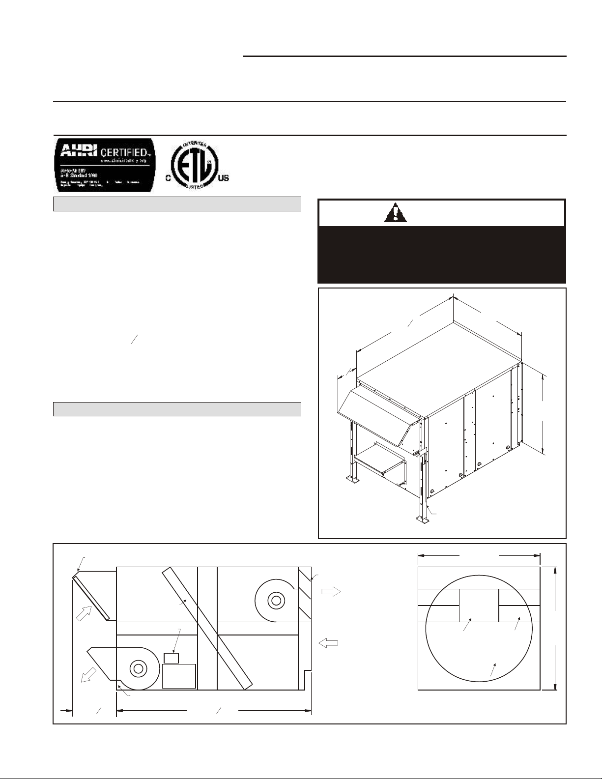
DELTA PRES SURE
FRESH AIR
DELTA PRES SURE
EX HAUST AIR
Figure 21
OPERATION
Recovery Wheel Mode
On a thermostat call for blower operation in heating,
cooling or continuous blower, the ERS media will rotate
between fresh air and exhaust air streams. Both the fresh
air blower and exhaust air blower will be operating.
Economizer/Power Exhaust Mode
On the activation of the economizer mode (closure of EH
and EH1 of logic module), the ERS unit will shutdown for
approximately60secondstoallowtheERS mediatopivot
out of the air stream. After this delay timer has been
satisfied,theexhaustairblowerwilloperate.TheERS unit
will act as a power exhaust unit.
This mode will continue until economizer has been
deactivated.Theexhaustairblowerwill shut downandthe
delay timer will be activated. During this time period the
ERS mediawillpivotback intotheairstream.Whentiming
is complete the unit will operate in the Recovery Wheel
Mode.
Then if economizer continues to close the ERS will
shutdown when the "N" terminal is deactivated, thus
allowing rooftop unit to run in night set back mode.
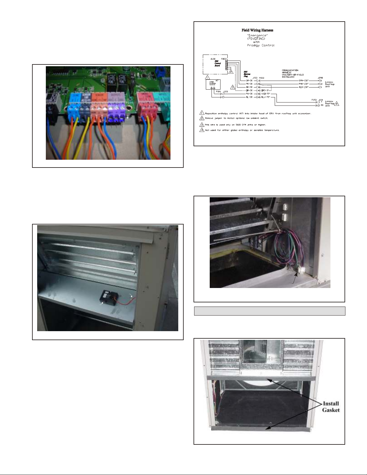
1. Disconnect ERS main power.
Note: If Low ambient kit S26 is used the jumper
between TB37-5 and TB37-6 should be removed.
Alsoifsystemcheck outisbeingconductedatlow
ambient temperatures, jumper low ambient
switch.
2. Open rooftop unit blower access panel and locate
TB1. Jumper terminals 6 (24v) and 3 (G) to energize
rooftop unit blower. Refer to manufacturers
instructions when an electronic thermostat or other
energy management system is used.
3. Remove ERS control access panel and install jumper
at low voltage terminal strip between TB37-1 and
TB37-2.
4. Restore power to ERS unit. The recovery wheel will
pivot out of the air stream, fresh air blower dampers
will open, and after a delay, the exhaust blower will
operate.
5. Remove jumper from ERS control board TB37-1 and
TB37-2. The recovery wheel will pivot into the air
stream, the fresh air blower dampers will close, and
after a delay, the fresh air blower and exhaust air
blower will operate.
SYSTEM CHECK
PAGE 7
MAINTENANCE
Motor Maintenance
All motors use prelubricated sealed bearings; no further
lubrication is necessary.
Mechanical Inspection
Make visual inspection of dampers, linkage assemblies
and ERS rotating bearings during routine maintenance.
Filters should be checked periodically and cleaned when
necessary. Filter is located in fresh air hoods. DO NOT
replace permanent filters with throwaway type filters.
Energy Wheel Maintenance
Four pie-shaped energy recovery wheel segments are
seated on stops between the stainless steel spring
retainers, secured to the hub and rim of wheel. Annual
inspection of the self cleaning wheel is recommended.
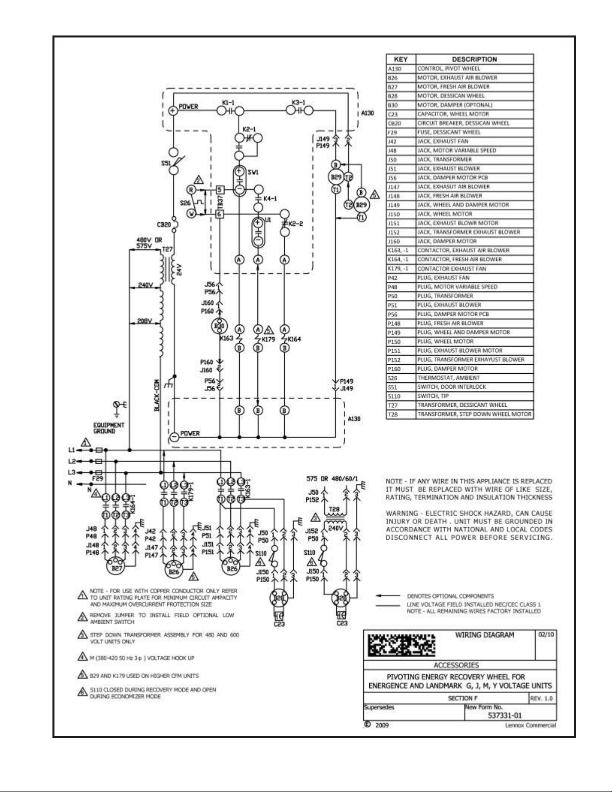
With power disconnected, remove ERS access panels
(rear)andunplug(J150&P150).Refertowiringdiagramin
this instruction manual. Each segment is secured in place
by a stainless steel spring retainer located on wheel rim.
Removeoneendof thestainlesssteelspringretainerfrom
the slot in the wheel rim and remove. Do the same on the
next retainer. Remove segment and wash with water
and/or mild detergent. Replace segment by reversing the
above procedure. See Fig ure 22. Discoloration and
staining of ERS segment does not affect its performance.
Only excessive buildup of foreign material need be
removed. If the segment appears excessively dirty, it
should be cleaned to ensure maximum operating
efficiency. Thoroughly spray plastic surface with
household cleaner such as Fantasticor equivalent
middledetergent and gently rinse with warm water usinga
soft brush to remove heavier accumulation. Shake excess
water from segment and replace in reverse of removal
instructions.
6. Disconnect main power to unit before making
adjustment to economizer and/or ERS unit.
7. Remove all jumpers and replace ERS control access
cover.
8. Set thermostat to normal operating position.
9. Restore power to unit.
HUB
SEGMENT
FIGURE 22
SPOKE
SEGMENT RETAINER CATCH
WHEEL RIM
SEGMENT RETAINER