TKR Group 83 30 5 A69 930 User manual

83 30 5 A69 930
R1-22.08-V1
Testing box for HV adapter cable sets GEN3/4/5
Translation of the original owner‘s manual

2
?
Owner‘s manual,
digital
Europe
Worldwide
www.tkr-service.comOwner‘s Manual USB-Stick
Owner‘s manual,
digital
Europe
Worldwide

3
1. Safety
1.1 General instructions 4
1.2 Explanation of symbols 5
1.3 Labelling 6
1.4 Scope of supply 6
1.5 Safety instructions 7
2. Technical Data
2.1 Technical Data 8
2.2 Device components 9
3. Installation
3.1 Intended use 10
3.2 Working with the tool - basic principles 10
3.3 Commissioning and safe handling 11
4. Application
4.1 Operation and use 12
4.1.1 Testing before use 12
4.1 Operation and use 13
4.1.2 With two-pole voltage tester 13
4.1 Operation and use 14
4.1.2 With multimeter 14
4.1 Operation and use 15
4.1.3 Sources of faults 15
4.2 Putting out of operation and storage 15
5. Maintenance
5.1 Troubleshooting 16
5.2 Regular checking and maintenance 16
5.3 Spare parts and accessories 16
6. Service
6.1 Disposal 18
6.2 Warranty and Service 18
6.3 EU Declaration of Conformity /
Declaration of Conformity 19
This owner‘s manual is protected by copyright. Any use beyond the restrictions imposed by copyright legislation undertaken without the permission of the manufacturer
is illegal and punishable by law. This also applies to the extraction of individual illustrations and use of texts as excerpts.
4
6.3
1.1 General instructions
State-of-the-art
This tool is state-of-the-art technology. To ensure that the equip-
ment operates safely, it must be operated in a proper and safety-
conscious manner.
Technical changes
In the interests of quality assurance, we reserve the unrestricted
right to carry out technical changes as a result of further techno-
logical developments and product improvements without prior
notication.
Reading the owner's manual
Before using the tool, make sure you read the owner's
manual carefully and understand it. This manual
must always be available where the product is used.
Handling
All the actions necessary to ensure correct operation are descri-
bed in the owner's manual. Any working methods other than
those approved by the manufacturer are prohibited.
Faults
If faults occur, the operator may only eliminate those faults
through their own actions where the corresponding remedy is
described.
Warranty
The manufacturer accepts no liability for damage or injury cau-
sed by improper repair or the use of third-party replacement
parts.
No warranty will be provided for damage caused to the device
due to the tool being used incorrectly.
Environment
Make sure that the tool is set up in a work area which is free from
sources of heat (max. 50°C / 122 °F), corrosive liquids, greases or
oils.
Declaration of Conformity
The tool has been manufactured in accordance with
international guidelines. The relevant declaration of
conformity (CE, UKCA, CB) is included with this ow-
ner’s manual.
Risk of damage to the tool
The tool must only be used as described in the ins-
truction manual. It is expressly forbidden to misuse
the tool or to use it for any other purpose. Please
make sure that you and your sta handle the tool
correctly.
Risk of injury
In addition to the owner's manual and the binding
provisions of the accident prevention regulations
which apply in the country and at the place of use,
you must also comply with the general (accepted)
rules for safe and professional working.
Electrician
Only trained and instructed personnel are authorized to carry
out the repair / maintenance work on the vehicles and vehicle
components concerned.
5
x.x
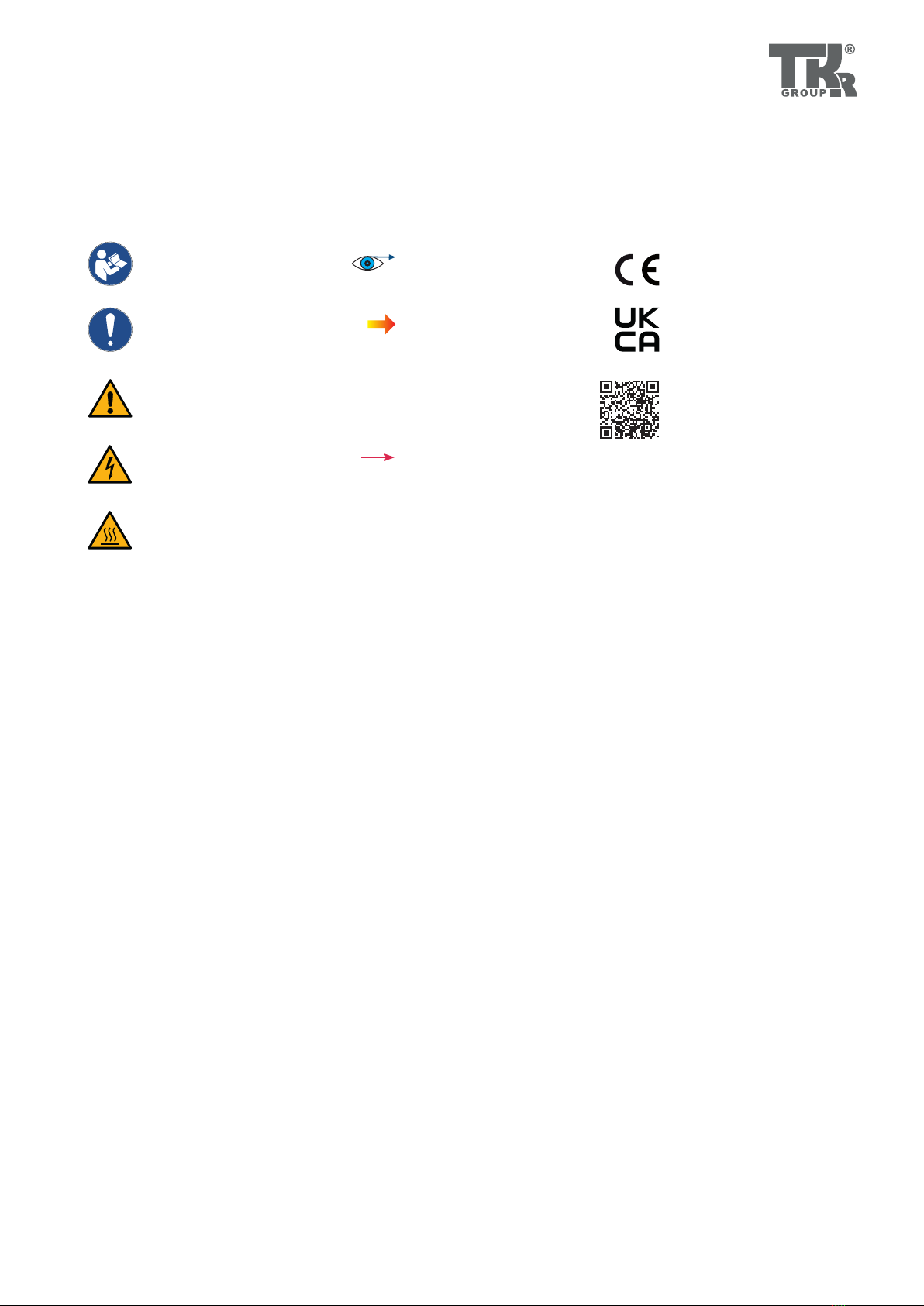
1.2 Explanation of symbols
Some chapters in this instruction manual use internationally recognised warning symbols, warning notes and general in-
struction symbols.
The individual symbols are explained below. Follow all the instructions and safety rules.
Follow the manual
Follow the general
instructions
Warning!
General source of danger
High voltage!
Danger to life!
Warning!
Hot surface
Please note
the following...
Arrow to clarify
compression
For more information,
see chapter …
Arrow showing direction
CE-mark
UK Conformity Assessment
Product certicate
https://www.tkrgroup.com/
83305A69930-cert.htm

6
A
B
B
D
C
G
JIH
EF
A
B
C
D
E
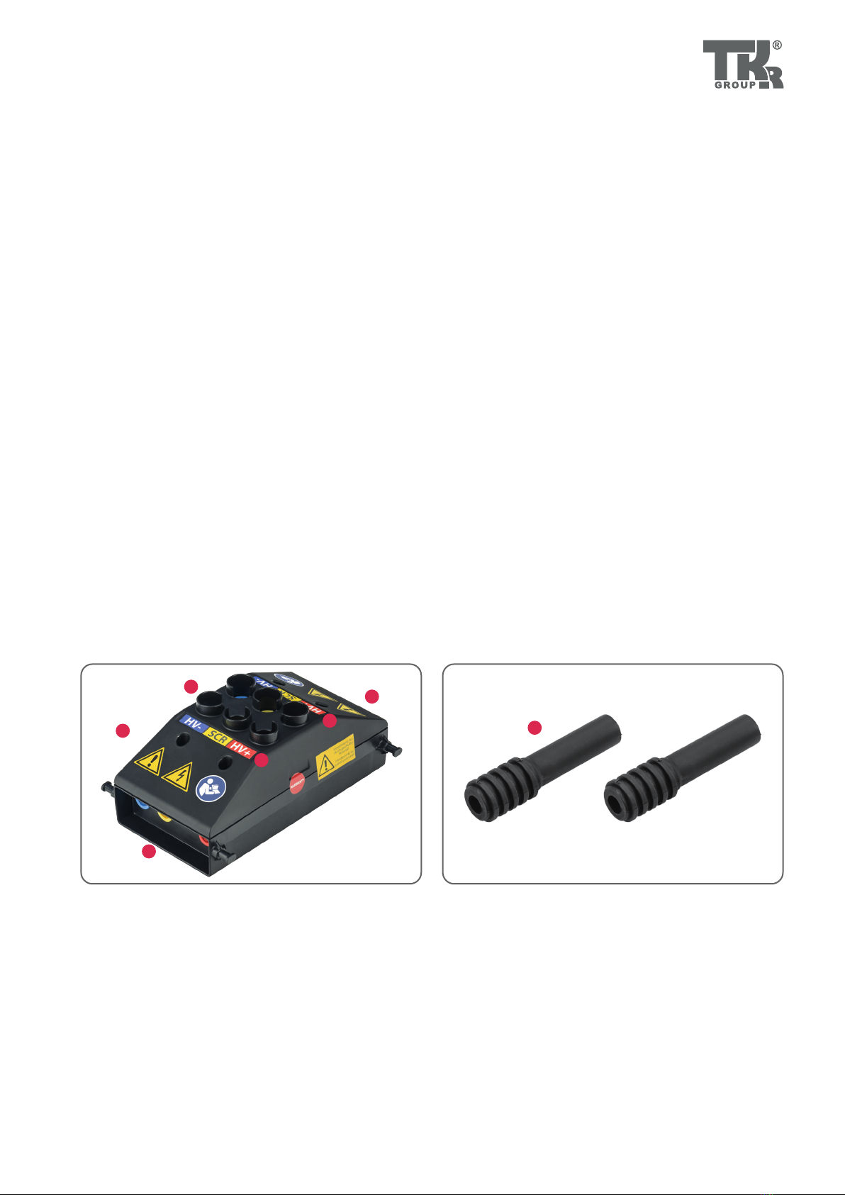
1.3 Labelling
Fig. 1 Fig. 2
Fig. 1
Testing box: labelling, top
A Three stickers (Warning!, High voltage!,
Follow owner‘s manual!)
B Designation of measurement points
C Warranty seal
D Seal with reference to trained personnel
Fig. 2
Testing box: labelling, bottom
E Manufacturer’s label and part number
F Item number and serial number
G Connection diagram
H Company address
I CE-mark, UKCA-mark, disposal
J Voltage and protection class
1.4 Scope of supply
A Testing box
B 2 x Reducing adapter 2 / 4 mm
D Owner’s manual
D USB stick
E Case
7
1.5 Safety instructions
If any abnormality is identied, the tool must not be used.
Please contact Service ( 6.2).
CAUTION
If used with the wrong accessories, this may
cause material damage and bodily injury.
Not using original tools and original accessories will
result in a high risk to safety. Only original accessories
may be used.
The manufacturer cannot accept any liability for con-
versions or modications to the tool.
CAUTION
Trip hazard
Laying supply cables carelessly can lead to accidents
through tripping, twisting of the ankle or falls or may
even damage the cables.
Lay all supply cables so that they cannot be damaged
and nobody can trip over them.
CAUTION
Risk of material damage and bodily injury
You must read and understand the safety instruc-
tions before carrying out the repair.
Not reading the instructions may result in serious
bodily injury.
CAUTION
Risk of material damage and bodily injury
Only technical personnel who have received inst-
ruction are authorized to operate this tool. The tool
must not be lent to untrained persons. Ensure that
the tool is only operated by trained personnel who
are instructed in its use!
CAUTION
Risk of damage to the tool
Not handling the tool properly can lead to damage to
the tool. Never throw the tool or allow it to fall.
CAUTION
Risk of personal injury
In order to avoid receiving an electric shock, make
sure that this tool is not connected to a power source
before carrying out any conguration, cleaning or
maintenance work on it. Just switching o the tool or
pressing the disconnecting button does not reduce
the risk.
Ensure that the owner's manual is made availa-
ble to the operating personnel.
Each operator must carefully read and understand
this owner's manual before using the tool for the rst
time. This owner's manual must always be available
where the product is used.
Follow the applicable national regulations for
the prevention of accidents.
In addition to the owner's manual and the binding
provisions of the accident prevention regulations
which apply in the country of use, you must also
comply with the general, accepted rules for safe and
professional working.
8
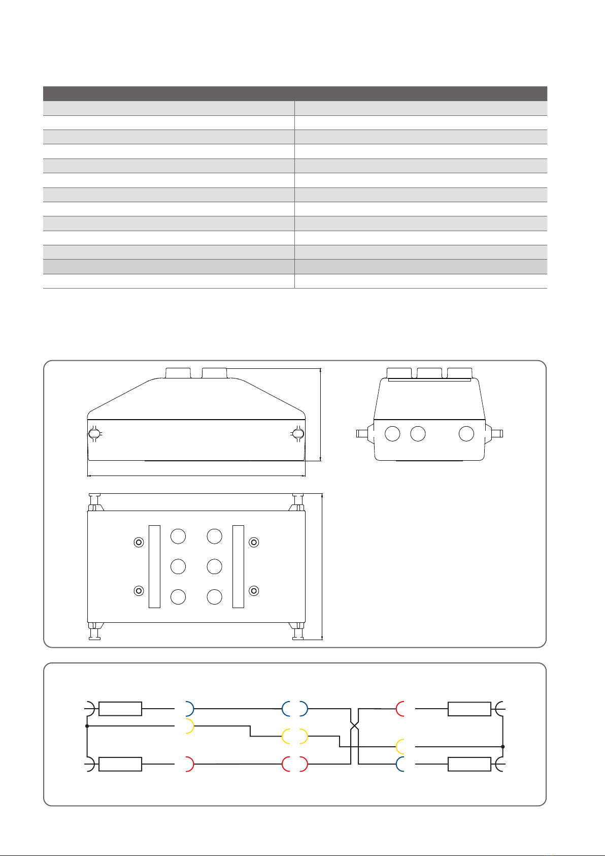
120.7
180
76.3
HV–
SCR
HV+
HV–
SCR
HV+
HV–
SCR
HV+
HV+
SCR
HV–
Art. Nr. 77-001070
HV–
SCR
HV+
47 kΩ
47 kΩ
77-001104
47 kΩ
47 kΩ
HV–
SCR
HV+
77-001105
2.1 Technical Data
Adapter end Adapter endHV Adapter
Connection diagram
83 30 5 A69 930
Type of device Measurement
Conguration Hand held
Supply connection None (passive)
Ambient temperature (operation) 5 °C to 45 °C / 41 °F to 113 °F
Ambient temperature (storage) -20 °C to +60 °C, to -4 °F +140 °F
Maximum application height 2000 m
Ambient humidity To 95 % (non-condensing)
Protection class IP 20
Measurement category CAT I*
Maximum measurement voltage (Umax) 1000 V DC
Impedance 47 kΩ HV +, 47 kΩ HV -
Weight 0.5 kg
Dimensions (W x H x D) 180 x 76.3 x 120.7 mm
* Measurements on electrical circuits which are not directly connected to the mains (e.g. battery operation and passenger car electrical circuits)
Fig. 1
Fig. 2
9
1
2
3
3
4
4
5
2.2 Device components
Voltage supply
No additional voltage supply is needed.
Climate conditions
Storage temperature: -40 °C to +60 °C / -40°F to +140 °F
Operating temperature: +5°C to +45 °C / +41 °F to +113 °F
Environmental humidity: up to 95% (not dew-forming)
Protection: IP20, CAT I, Degree of contamination 2
Climate class: 3K3
Fig. 1
[1] Testing box
[2] Annular contact sockets, 4 mm
[3] Labelling of annular contact sockets
[4] Plug connector Testing box (socket)
Fig. 1
Fig. 2
[5] Reducing adapter
Fig. 2
10
3.1 Intended use
The testing box is used in workshops to make sure there is no live
voltage or insulation defects on HV motor vehicle on-board elec-
trical systems. Dierent types of plug connectors are therefore
included in the scope of supply for connection to the dierent
HV components.
A trained user can use suitable testing and measurement inst-
ruments to check the voltage or use guided troubleshooting to
nd faults on the HV system.
As a rule, never work on live parts of the electrical system or
equipment. Before starting work, live parts must therefore be
de-energised and this state checked and guaranteed for the
duration of the work.
The testing and measurement instruments used
must be approved and must be suitable for the
voltage being measured (label on the instrument
at least CAT I and the max. operating voltage pre-
sent, e.g. CAT I 1000 V).
3.2 Working with the tool - basic principles
Risk of injury
It is vitally important that you make sure that you are handling the tool correctly.
It is expressly forbidden to misuse the tool or to use it for any other purpose.
The tool must only be used as described in the instruction manual.
Warranty
The manufacturer accepts no liability for damage or injury caused by improper repair or
the use of third-party replacement parts.
No warranty will be provided for damage caused to the device due to the tool being used
incorrectly.
Environment
The tool may only be used in a work area which is free of sources of heat (max.
45 °C / 113°F), corrosive liquids, greases and oils.
Leave to acclimatise before starting.
Avoid the formation of condensation.
Make sure that the area is well ventilated to avoid the build-up of explosive
vapours.
Declaration of Conformity
The tool has been manufactured and tested in accordance with the European directives.
The Declaration of Conformity is included with this owner's manual.
6.3

11
3.3 Commissioning and safe handling
Check the HV Adapter Set for any damage every
time before using it.
Always carry out a visual inspection of the spring
contacts before use.
A self-test must always be carried out on the tool
to make sure that it is in perfect working order
before using it.
HV– to HV– Resistance 94 kΩ, Tolerance 1 %
HV+ to HV+ Resistance 94 kΩ, Tolerance 1 %
SCR to SCR Resistance 0 Ω
HV+ to HV– Resistance > 10MΩ
HV– to HV+ Resistance > 10MΩ
HV+ to SCR Resistance > 10 MΩ
HV– to SCR Resistance > 10 MΩ
Fig. 1 Fig. 3
Check the measurement instrument for damage
and check operation before carrying out any
measurement.
Before using the HV Adapter Set, check whether
the relevant thermal sticker on the adapter ends
is in order.
3.3.5
Fig. 1
Plug the connector together.
Fig. 2
Test set-up for self-test
During the self-test, all the plugs and sockets must be connected
to each other and the adapter ends plugged into the HV Adapter
and locked.
Fig. 2
Fig. 3
Test set-up for resistance tests
Now carry out the following resistance tests with a suitable
measurement instrument and compare the results with the table
below:
If the measurement values shown above do not
appear during the self-test, the HV adapter set
must not be used!
12
°
0
8
F
1
8
C
2
°
°
0
8
F
1
8
C
2
°
7
3
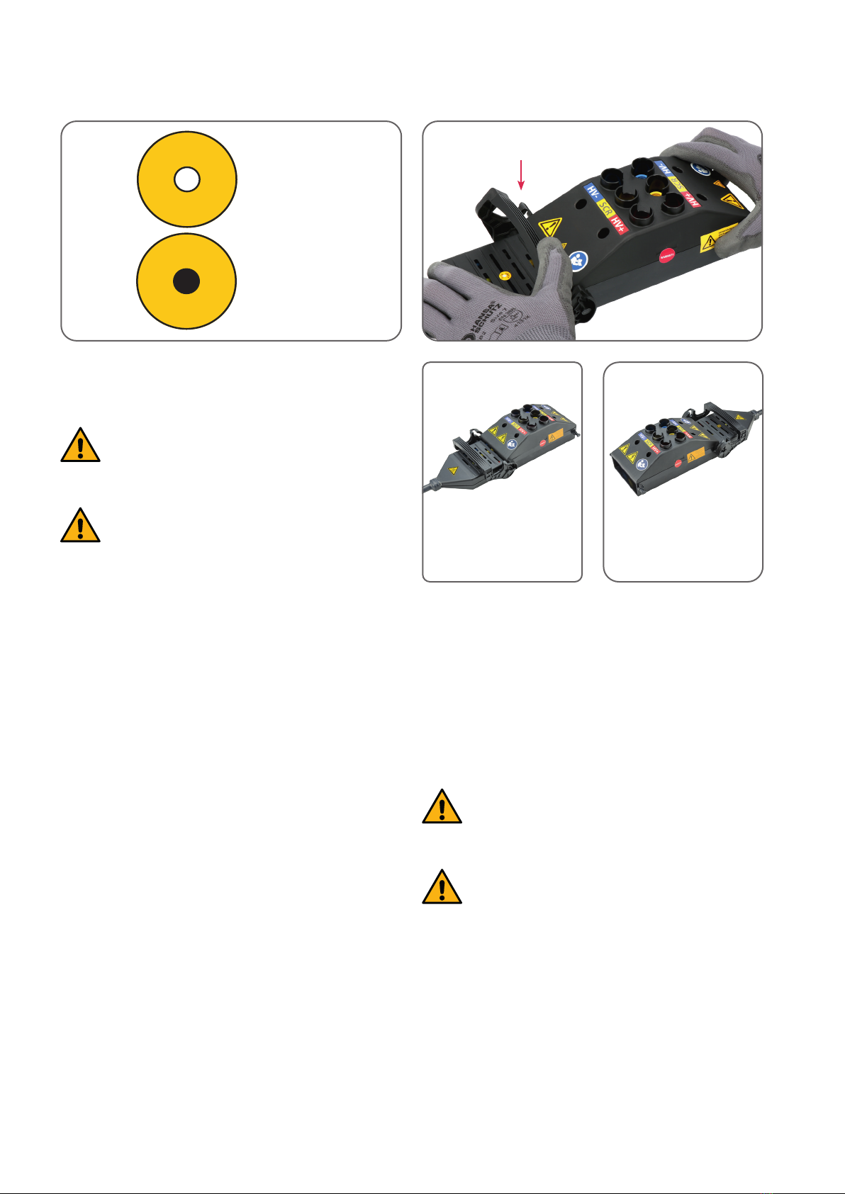
Fig. 1
Thermal sticker: Testing before use
Before using the HV Adapter Set, check whether
the relevant thermal sticker on the adapter ends
is in order (white dot in the centre).
If the dot in the centre of the thermal sticker has
gone black, the temperature has exceeded 82 °C
/ 180 °F and the adapter must not be used!
Fig. 2–4
Connecting HV components
Connect each adapter cable needed to the testing box and se-
cure it with the clamp.
Now connect the corresponding pin / socket housing of the
adapter cable to the HV components.
When connecting two HV components, never
connect the HV+ and HV- connections to the op-
posing HV+ and HV- connections.
If there is bridging or short circuiting, the adap-
ter cables must be changed immediately.
Connection to HV components
with pin or socket contact
Connection to HV components
with pin or socket contact
Fig. 1
4.1 Operation and use
4.1.1 Testing before use
Fig. 2
Fig. 3 Fig. 4

13
Fig. 5
Checking to make sure there is no live voltage with two-
pole voltage tester
The supplied reducing adapters are used depending on the
diameter of the test connections (2 mm /4 mm) of the testing /
measurement instrument used and are plugged into the corre-
sponding measurement sockets.
Never use two-pole voltage testers with 2 mm
test connections without the reducing adapters.
The voltage tester used must be approved and
must be suitable for the voltage being tested.
Suitable testing / measurement instruments
must be used to make sure there is no live voltage
when testing with the HV Adapter Set!
(Label on the testing / measurement instrument
at least CAT I and the max. operating voltage pre-
sent, e.g. CAT I 400 V)
Check the testing / measurement instrument for
damage and check operation before carrying out
any measurement.
Check the testing / measurement instrument with a known vol-
tage source to make sure it is operating properly.
Fig. 6, 7
Testing:
Voltage tester across HV+ and HV-
Voltage tester across HV+ and SCR
Voltage tester across HV- and SCR
The voltage tester may only display voltages below 60 V during
the tests.
If there are deviations, the procedure must be repea-
ted with a multimeter.
During the testing procedures, make sure that
you only select the measurement sockets on the
side of the adapter end plugged in!
The connections with the same designation are
not connected to one another!
If the voltage is higher than 60 V DC, the entire
HV system must be regarded as DANGEROUSLY
ACTIVE.
You must not continue working on live HV com-
ponents!
Note that the deviation is greater when using
testing / measurement instruments with a lower
internal resistance.
A voltage tester usually has an internal resistance of 200 kΩ.
When the voltage which appears is 60 V, the
actual voltage is approx. 88 V.
Internal resistance Deviation
5 MΩ approx. 2 %
1 MΩ approx. 9 %
200 kΩ approx. 32 %
Fig. 5 Fig. 6 Fig. 7
4.1.3
4.1.4
4.1 Operation and use
4.1.2 With two-pole voltage tester

14
4.1 Operation and use
4.1.2 With multimeter
Fig. 1
Preparation test/measurement instrument
The testing / measurement instruments used
must be approved and must be suitable for the
voltage being tested.
The test leads used must be touch protected and
approved and must be suitable for the voltage
being tested.
Suitable testing / measurement instruments
must be used to make sure there is no live voltage
when testing with the HV Adapter Set!
(Label on the testing / measurement instrument
at least CAT I and the max. operating voltage pre-
sent, e.g. CAT I 1000 V)
Check the testing / measurement instrument for
damage and check operation before carrying out
any testing procedures.
Set the testing / measurement instrument to a suitable DC volta-
ge measurement range. Switch o the automatic measurement
range switching.
Check the testing / measurement instrument with a known vol-
tage source to make sure it is operating properly.
Fig. 2
Checking to make sure there is no live voltage
The testing / measurement instrument must be
set to DC voltage and the automatic measure-
ment range change-over must be switched o.
During the testing procedures, only select the
measurement sockets on the side of the adapter
end plugged in!
Connections with the same designation are not
connected to one another!
If the voltage is higher than 60 V DC, the entire
HV system must be regarded as DANGEROUSLY
ACTIVE.
Be aware of possible errors in the voltage check
due to the voltage drop across the internal resis-
tance.
You must not continue to work on live HV compo-
nents!
To test potentials against the screen (SCR), rst use suitable test
leads to connect the COM port of the testing / measurement ins-
trument to the SCR (screen) connection of the HV Adapter Set.
Connect the (V) connection of the testing / measurement ins-
trument to the HV+ or HV- connection being measured. The
resulting voltage can now be read on the meter.
To test voltages across HV+ and HV-, connect the COM port of
the testing / measurement instrument to the HV- connection of
the HV Adapter Set and the (V) connection of the testing / mea-
surement instrument to the HV+ connection of the HV Adapter
Set.
The voltage of each testing procedure must be zero.
Fig. 1 Fig. 2

15
4.1 Operation and use
4.1.3 Sources of faults
Testing results/testing errors
The HV Adapter Set contains two 47 kΩ resistors in each adapter
connection plug in the HV+ line and the HV- line.
These resistors cause a voltage drop during the voltage testing
which depends on the internal resistance of the testing / measu-
rement instrument used. This voltage drop causes the reading
on the testing / measurement instrument to be lower than the
actual voltage.
On a standard testing / measurement instrument with an in-
ternal resistance of 10 MΩ (10,000 kΩ), the voltage drop in the
HV adapter is approx. 1 % of the actual voltage. In this case, the
measured voltage is 1% less than the actually available voltage.
Internal resistance Deviation
5 MΩ approx. 2 %
1 MΩ approx. 9 %
200 kΩ approx. 32 %
Note that the deviation is greater when using
testing / measurement instruments with a lower
internal resistance.
In the event of misuse, the resistors integrated in
the adapter ends heat up!
Example:
If the internal resistance of the testing / measurement instrument
is 200 kΩ and the measured voltage is 60V, the actual voltage
across the HV accumulator is approximately 88 V.
4.2 Putting out of operation and storage
Check the tool for any damage before and after each use.
Make sure that the tool is stored in a dry and warm place.
Avoid contamination.
Clean all parts carefully before storing. Store the tool in the case.

16
5.2 Regular checking and maintenance
5.3 Spare parts and accessories
Cleaning
Apart from occasional cleaning with a dry, lint-free cloth, the
Testing boxt is maintenance-free.
5.1 Troubleshooting
Malfunction Problem Remedy Chapter
The measurement values specied are
not measured during the self-test.
There is a fault in the adapter cable (e.g.
due to incorrect use). Change adapter cables. 3.3
The colour of the thermal sticker has
changed from white to black in the
center.
The integrated resistors have heated up
due to incorrect use. Change adapter cables. 3.4
Service
Do not carry out any service activities on this device.
Spare parts for Testing box 83 30 5 A69 930
BMW
Item no.
TKR
Item no. Designation Pcs. Set Partial refe-
rence path
83 30 5 A69 930 Testing box for HV adapter cable sets
GEN3/4/5 1 83 30 5 A69 930 BMW
99-000439 Adapter XA 2/4 2 83 30 5 A69 930 TKR
DOK-BMW-10000013 Owner's Manual 1 83 30 5 A69 930 TKR
WZK-BMW-10000007 Case 1 83 30 5 A69 930 TKR
Spare parts for Adaptor Cable (Set) GEN5, Connector system Kostal KS22, 83 30 5 A55 B86
BMW
Item no.
TKR
Item no. Designation Pcs. Set Partial refe-
rence path
83 30 5 A55 B86 Adaptor cable (Set) Kostal KS22 1 83 30 5 A55 B86 BMW
BGR-BMW-10000136 Adaptor cable Socket housing
Kostal KS22 1 83 30 5 A55 B86 TKR
BGR-BMW-10000137 Adaptor cable Pin housing
Kostal KS22 1 83 30 5 A55 B86 TKR
DOK-BMW-10000015 Owner's Manual 1 83 30 5 A55 B86 TKR
Spare parts for Adaptor Cable (Set) GEN5, Connector system Rosenberger HVS240, 83 30 5 A44 4A2
BMW
Item no.
TKR
Item no. Designation Pcs. Set Partial refe-
rence path
83 30 5 A44 4A2 Adaptor cable (Set) 1 83 30 5 A44 4A2 BMW
BGR-BMW-10000126 Adaptor cable Socket housing Rosenber-
ger HVS240 1 83 30 5 A44 4A2 TKR
BGR-BMW-10000127 Adaptor cable Pin housing
Rosenberger HVS24 1 83 30 5 A44 4A2 TKR
DOK-BMW-10000006 Owner's Manual 1 83 30 5 A44 4A2 TKR

17
Spare parts for existing HV Adaptor Set GEN5, Connector system Rosenberger HVS420 and Hirschmann HPS40-2,
83 30 5 A33 FD8
BMW
Item no.
TKR
Item no. Designation Pcs. Set Partial refe-
rence path
83 30 5 A33 FD8 HV Adaptor Set GEN5 1 83 30 5 A33 FD8 BMW
83 30 5 A2F 674 Adaptor cable set,
Rosenberger HVS420 1 83 30 5 A2F 674 BMW
BGR-BMW-10000122 Adaptor cable socket housing,
Rosenberger HVS420 1 83 30 5 A2F 674 TKR
BGR-BMW-10000123 Adaptor cable pin housing,
Rosenberger HVS420 1 83 30 5 A2F 674 TKR
83 30 5 A2F 675 Adaptor cable set,
Hirschmann HPS40-2 1 83 30 5 A2F 675 BMW
BGR-BMW-10000124 Adaptor cable socket housing,
Hirschmann HPS40-2 1 83 30 5 A2F 675 TKR
BGR-BMW-10000125 Adaptor cable pin housing,
Hirschmann HPS40-2 1 83 30 5 A2F 675 TKR
DOK-BMW-10000004 Owner's Manual 1 83 30 5 A33 FD8 TKR
Spare parts for existing HV Adaptor Set GEN3/4, Connector system Kostal PLK 14.5 and Hirschmann HPS40-1,
83 30 2 449 661
BMW
Item no.
TKR
Item no. Designation Pcs. Set Partial refe-
rence path
BGR-BMW-10000067 Adapter cable pin housing,
Kostal PLK 14.5 1 83 30 2 449 661 TKR
BGR-BMW-10000068 Adapter cable socket housing,
Kostal PLK 14.5 1 83 30 2 449 661 TKR
BGR-BMW-10000069 Adapter cable pin housing,
Hirschmann HPS40-1 1 83 30 2 449 661 TKR
BGR-BMW-10000070 Adapter cable socket housing,
Hirschmann HPS40-1 1 83 30 2 449 661 TKR
DOK-BMW-10000009 Owner's Manual 1 83 30 2 449 661 TKR
Other languages, accessories and spare parts:
www.tkr-service.com

18
6.2 Warranty and Service
Tools from TKR Spezialwerkzeuge GmbH come with a 24 month warranty against material and manufacturing defects.
Otherwise, the statutory conditions governing warranty periods and our General Terms and Conditions of Sale and Supply
apply.
High voltage components are not included.
The warranty begins on the date of delivery, as specied on the invoice or delivery note.
The warranty shall be valid for the user / customer provided that the tool is obtained from an authorized sales outlet and
is used as described in the instructions and for the purposes for which it was designed.
The warranty shall be invalidated if the tool is used for any purposes other than those for which it was designed.
Furthermore, the warranty shall be invalidated if the tool is not used as described in the owner's manual.
In the event of a defect or fault, TKR Spezialwerkzeuge GmbH shall only repair or replace faulty parts at its own discretion.
Service address TKR Spezialwerkzeuge GmbH
Service
Am Waldesrand 9–11
D-58285 Gevelsberg (Germany)
Online-Service www.tkrgroup.com/service
Other language versions, assistance with use and information
Visit our Customer Service area.
Devices and machinery and components of devices and machinery must be disposed of in compliance with the
laws, regulations and other stipulations of the country in which they are located.
We recommend using specialist licensed companies for disposal.
The modules and units have been developed to be environmentally compatible and suitable for recycling. According to
the EU Directive 2002/96/EC, these parts must be taken to authorized collection points.
Batteries and rechargeable batteries - including button cells - do not belong in the residual waste bin, but must be dispo-
sed of properly.
The manufacturer does not promise to take back modules and components of electrical equipment or electrical equip-
ment in its entirety or batteries at no cost.
6.1 Disposal

19
6.3 EU Konformitätserklärung6.3 EU Declaration of Conformity /
Declaration of Conformity
EU Declaration of Conformity
For the purposes of the low voltage directive
2014/35/EU
Manufacturer: TKR Spezialwerkzeuge GmbH
Am Waldesrand 9–11
58285 Gevelsberg, Germany
Person authorised to compile
the technical documentation: Thorsten Weyland
Type of tool: Testing box for HV adapter cable sets
Type designation: 83 30 5 A69 930
Developed and constructed in accordance with
the standards and guidelines listed by
TKR Spezialwerkzeuge GmbH
Am Waldesrand 9–11
58285 Gevelsberg (Germany)
Harmonised standards used: EN 61010-031:2016
Serial number range: 00001–10000
Low voltage directive: 2014/35/EU
As manufacturer, we declare: The products marked accordingly fulfill the
requirements of the directive and standards listed.
Gevelsberg, 28.03.2022 Thorsten Weyland
Technical Manager
EU Declaration of Conformity
In compliance with the low voltage directive 2014/35/EU
Tool type: Testing box for HV adapter cable sets
Type designation: 83 30 5 A69 930
Serial number range: 0001–1000
Has been developed and designed in compliance with
thestandardsanddirectivesspeciedbelowby
Manufacturer TKR Spezialwerkzeuge GmbH
Am Waldesrand 9–11
DE-58285 Gevelsberg
Person authorised to compile
the technical documents: Thorsten Weyland
Harmonised standards used: EN 61010- 1:2010/A1:2019/AC:2019-04
EN 61010-1:2010/A1:2019
EN IEC 63000:2018
Directives: Low voltage directive 2014/35/EU
RoHS 2011/65/ EU
As manufacturer, we declare: The products marked accordingly fulfil the requirements
of the directive and standards listed.
Town and date: Gevelsberg, 28.03.2022
Signature:
Thorsten Weyland
Technical Director

21
EU Declaration of Conformity
For the purposes of the low voltage directive
2014/35/EU
Manufacturer: TKR Spezialwerkzeuge GmbH
Am Waldesrand 9–11
58285 Gevelsberg, Germany
Person authorised to compile
the technical documentation: Thorsten Weyland
Type of tool: Testing box for HV adapter cable sets
Type designation: 83 30 5 A69 930
Developed and constructed in accordance with
the standards and guidelines listed by
TKR Spezialwerkzeuge GmbH
Am Waldesrand 9–11
58285 Gevelsberg (Germany)
Harmonised standards used: EN 61010-031:2016
Serial number range: 00001–10000
Low voltage directive: 2014/35/EU
As manufacturer, we declare: The products marked accordingly fulfill the
requirements of the directive and standards listed.
Gevelsberg, 28.03.2022 Thorsten Weyland
Technical Manager
Declaration of Conformity
Tool type: Testing box for HV adapter cable sets
Type designation: 83 30 5 A69 930
Serial number range: 0001–1000
The product is developed and constructed in accordance
with the UK legislation and designated standards by
Manufacturer TKR Spezialwerkzeuge GmbH
Am Waldesrand 9–11
DE-58285 Gevelsberg
Person authorised to compile
the technical documents: Thorsten Weyland
Applicable UK legislation: Electrical Equipment (Safety) Regulations 2016
The Restriction of the Use of Certain Hazardous
Substances in Electrical and Electronic Equipments
Regulations 2012
UK Designated Standards: EN 61010- 1:2010/A1:2019/AC:2019-04
EN 61010-1:2010/A1:2019
EN IEC 63000:2018
As manufacturer, we declare: The products marked accordingly fulfil the requirements
of the directive and standards listed.
Town and date: Gevelsberg, 28.03.2022
Signature:
Thorsten Weyland
Technical Director
Table of contents
Other TKR Group Test Equipment manuals


