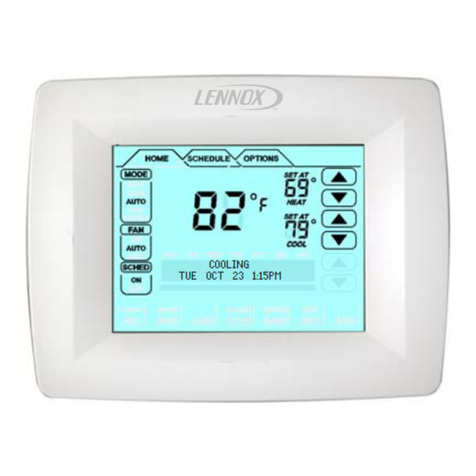
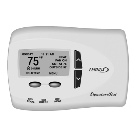
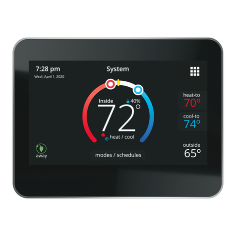
Optional Accessories for use with any iComfort®system
iComfort®Communicating Systems iComfort®-enabled Indoor Unit / Non-Communicating Outdoor Unit
iComfort Wi‐Fi®Thermostat
iComfort®Indoor Furnace or Air Handler
Non-Communicating Air Conditioner
FURNACE (IFC) OR
AIR HANDLER (AHC)
iComfort
Wi‐Fi®
iComfort Wi‐Fi®Thermostat
iComfort®Air Handler
Non-Communicating Heat Pump
Conventional
24V AC or
HP (1 or 2
Stage)
iComfort Wi‐Fi®Thermostat
iComfort®Indoor Furnace or Air Handler
Non-Communicating Air Conditioner
iComfort Wi‐Fi®
Thermostat
Discharge Air
Sensor (required
for even heat)
(see DAS note)
iComfort®-enabled
Furnace or Air handler
iComfort®Outdoor Air
Conditioner or Heat
Pump Unit
NOTE: iComfort Wi‐Fi®thermostat senses humidity
and controls 24VAC H output (and 120VAC HUM out
put) to cycle humidifier based on demand. No other
control or humidistat required.
Optional outdoor air sensor for use with humidifier (if
not already in the system for other functions. Built into
all iComfort®outdoor units. (see OAS note)
Non-Communicating 1 or
2-Stage AC or HP un it
DAS NOTE: The discharge air sensor is intended to be
mounted downstream of the heat exchanger and air condi
tioning coil. It must be placed in free airflow, where other ac
cessories (such as humidifiers, UV lights, etc.) will not inter
fere with its accuracy. Wiring distance between the IFC or
AHC and the discharge air sensor should not exceed 10
feet when wired with 18-gauge thermostat wire.
OAS NOTE: The outdoor temperature sensor wiring dis
tance between the IFC or AHC should not exceed 200 feet
when wired with 18-gauge thermostat wire.
RSBUS NOTE Maximum total length of all connections on
the RSBus is limited to 1500 ft. (450 m). Max. length
between components is 300 ft. (90 m).
Optional
Discharge Air
Sensor (see
DAS Note)
Furnace (IFC) or Air
Handler (AHC)
SLP98 & G71MPP
Furnace (IFC) or Air
Handler (AHC)
RSBus
Optional
Outdoor Air
Sensor (see
OAS note)
RSBus
Air Handler (AHC)
NOTE - If electric heat strips are used, the strips
MUST be configured on the air handler control
(AHC) board before beginning the “discovery” se
quence as described in the Installer's Guide.
IMPORTANT!
BEFORE POWERING THERMOSTAT
iComfort
Wi‐Fi®
(POWER COMPANY
INTERRUPTION
SYSTEMS ARE WIRED
SAME AS OVERFLOW
SWITCH)
RSBus
Maximum total length
of all connections on
the RSBus is limited to
1500ft.
Wire gauge of RSBus
wire is 18.
iComfort®-2-Stage
Furnace
CUT
R-DS
W914
DS
R
iComfort®- Furnace or
Air Handler
iComfort by Lennoxt
Furnace or Air Handler
HEPA Bypass Filter X2680 HEPA
Interlock Kit
Pass indoor
blower motor
common wire
through cur
rent loop.
See HEPA In
terlock Kit for
installation
details
Rf WGhGsCf
HVAC EQUIP
HCWH-01 Dehumidifier
Control
HVAC
Equipment
DH NC
AUXILIARY DEHUMIDIFIER 090 & 135
capacities only (065 not compatible)
NOTE: 24V UV LIGHT APPLICATIONS
In an iComfort™-enabled system, neither furnace
nor air handler transformer will have adequate VA to
power 24V UV light applications. An additional
transformer for UV light applications is required. UV
light wiring connections are independent of HVAC
system operation; see UV light installation instruc
tions for transformer VA requirements and wiring de
tails.
SL280, EL296 FURNACE
48G96 Relay
GND
IN
iComfort
enabled
outdoor unit
iComfort
Wi‐Fi®
thermostat
120VAC<-------HUMIDIFIER CONNECTIONS------> 24VAC
Indoor Unit
Controller
Outdoor Unit
iComfort Wi‐Fi®
thermostat
Single wire to
terminal C
Single wire to
terminal C
Unused wires
Unused wires
Communicating systems using the iComfort Wi‐Fi®thermostat re
quire four thermostat wires between the thermostat and the fur
nace/air handler control and four wires between the outdoor unit
and the furnace/air handler control. When a thermostat cable with
more than four wires is used, the extra wires must be properly con
nected to avoid electrical noise. The wires must not be left discon
nected.
Use wire nuts to bundle the unused wires at each end of the cable.
A single wire should then be connected to the indoor unit end of the
wire bundle and attached to the “C” terminals as shown in the dia
gram above.
This is not an issue in non-communicating systems.
Thermostat wire termination in iComfort®system
For SL290 & EL296, see HUMIDIFIER diagram below
IMPORTANT! - Thermostat does not support a NON-communicating HEAT
PUMP with communicating FURNACE (dual fuel).
26L56 Current sensing relay kit.
NOTE: Pass the blower motor L1 wire
through the current loop on the current
sensing relay as shown.
HVAC Heat or Cool call, or the fan is in con
tinuous operation, the ventilation controller
will open OA damper to ventilate if the out
door temperature and indoor humidity are
within the limits of the ventilation controller.
LVCS. Set cycle time to 1 hour; set ventila
tion time to 60 minutes.
NOTE: Use the iComfort®circulate fan per
centage of ON* TIME to control ventilation
time.
Optional
Outdoor Air
Sensor (see
OAS note)
iComfort
Wi‐Fi®
Optional
Discharge Air
Sensor (see
DAS Note)
Conventional
24V HP (1 or
2 Stage)
iComfort™-enabled
AC or HP (1 or 2
Stage)
Optional
Discharge Air
Sensor (see
DAS Note) Optional
Outdoor Air
Sensor (see
OAS note)
RSBus
iComfort
Wi‐Fi®
Non-communicating 24V
AHC or Furnace or Air
Handler (1 or 2 Stage)
iComfort Wi-Fi®Thermostat, Comfort®-enabled
Equipment Interface Module / indoor unit and
Non-Communicating Indoor Unit
iComfort™-enabled
Equipment Interface
Module (EIM)
iComfort Wi-Fi®Thermostat, iHarmony®Damper Control
Module and Communicating indoor Unit
iComfort™-enabled
indoor unit unit
See Equipment Interface
Module Installation instructions
for additional configurations.
iComfort Wi‐Fi®
Thermostat
RSBus
LVCS Ventilation Control System
SLP98 & G71MPP Furnace
(IFC) or Air Handler b (AHC)
f
Vent ODT


