Lenovo ThinkCentre M910x Owner's manual

M910x
User Guide and
Hardware Maintenance Manual
Machine Type (MT):
10MY, 10N0, 10N1, 10N2, 10QQ
Energy Star MT:
10MY, 10N0, 10N1, 10N2, 10QQ
Overview
Locations of indicators,
connectors, and
controls provided on
your computer
Replaceable parts
Locations of the
replaceable parts on
your computer
Specications
Specications of your
computer
Replacing FRUs
Replacing instructions
for eld-replaceable
units (FRUs) (for
technicians only)
Computer locks
Locking devices for
your computer
Replacing CRUs
Replacing instructions
for customer-
replaceable units
(CRUs)

2
Overview.........................................3
Front view....................................................................... 3
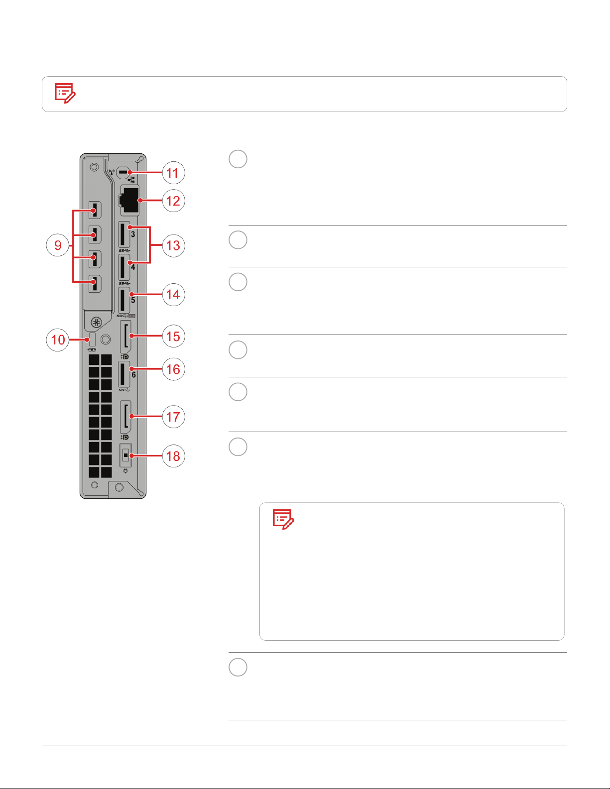
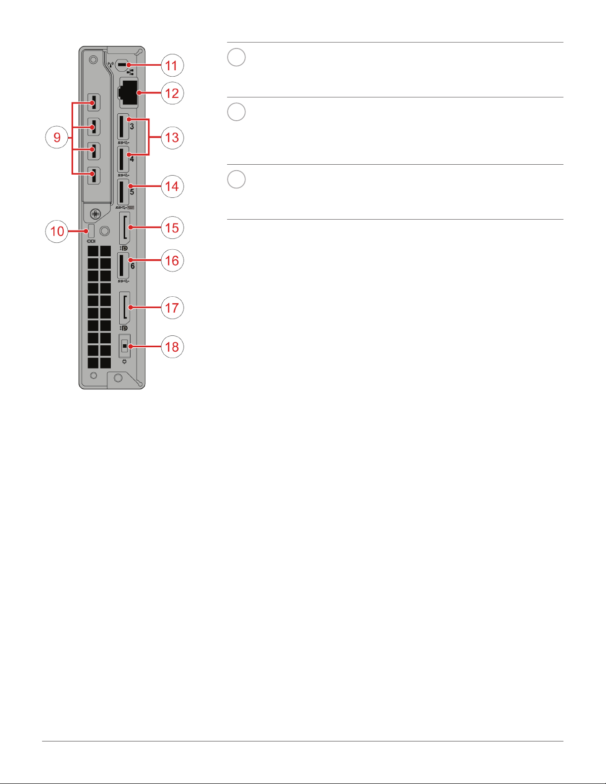
Rear view........................................................................ 4
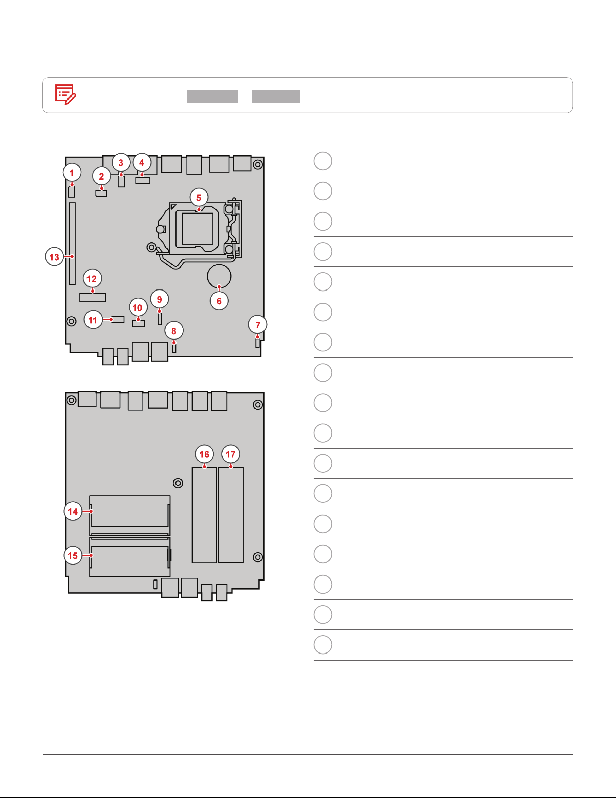
System board................................................................6
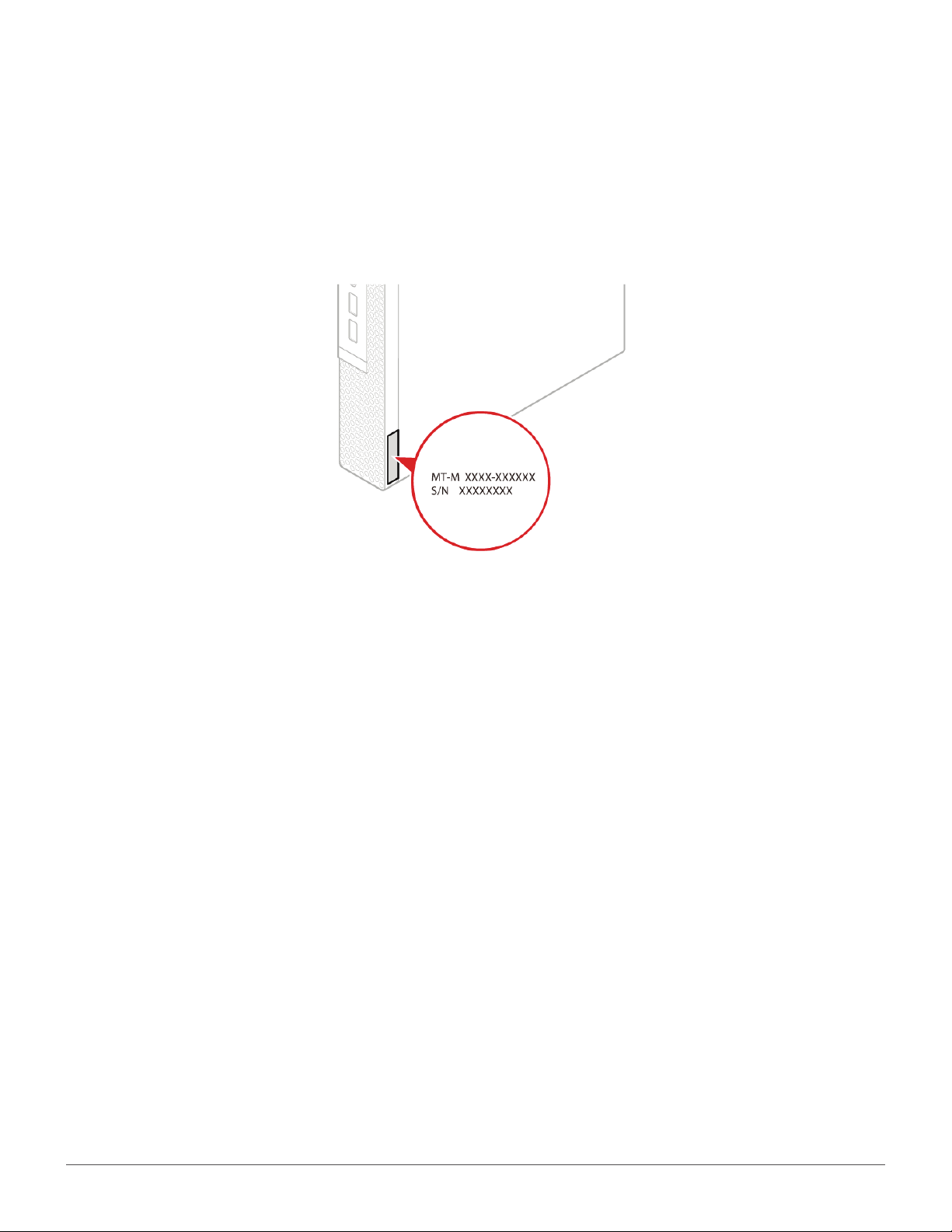
Machine type and model label................................... 7
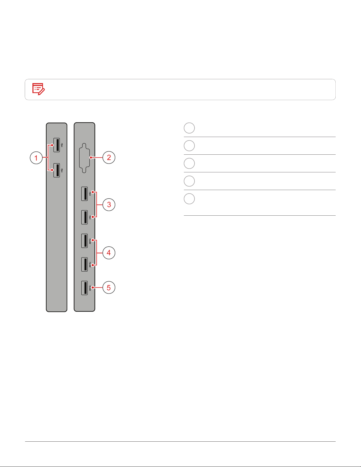
I/O box............................................8
Overview.........................................................................8
Using the I/O box.......................................................... 9
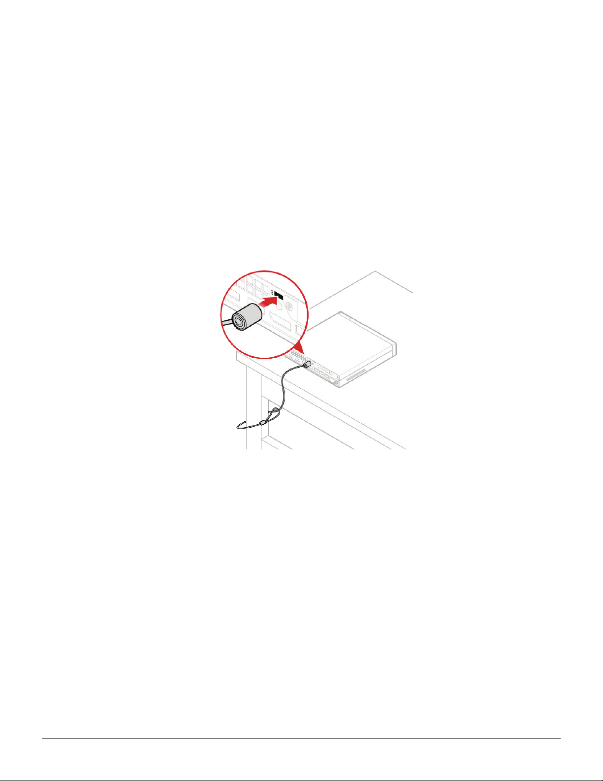
Computer locks ............................10
Attaching a Kensington-style cable lock ...............10
Specications...............................11
Replacing hardware......................12
Before replacing hardware .......................................12
Handling static-sensitive devices...........................12
Knowing replaceable parts.......................................13
Customer-Replaceable Units (CRUs).......................... 13
Field-Replaceable Units (FRUs).................................... 13
CRUs and FRUs locations..............................................14
Replacing CRUs............................17
Before replacing CRUs ..............................................17
Replacing the keyboard or wireless keyboard......19
Replacing the keyboard .................................................. 19
Replacing the wireless keyboard.................................. 19
Replacing the mouse or wireless mouse ..............20
Replacing the mouse ...................................................... 20
Replacing the wireless mouse ...................................... 20
Replacing the power adapter...................................22
Replacing the vertical stand.....................................23
Replacing the VESA mount bracket........................24
Replacing the external optical drive........................25
Replacing the external I/O box ................................26
Replacing the power adapter bracket ....................27
Removing the computer cover ................................28
Replacing the storage drive......................................29
Replacing the internal speaker ................................30
Replacing the system fan.........................................31
Replacing the PCI Express card and PCI Express
card adapter ................................................................32
Replacing the Wi-Fi card...........................................34
Replacing the bottom cover.....................................37
Replacing the memory module ...............................38
Replacing the M.2 storage drive..............................39
Completing the parts replacement.........................40
Replacing FRUs ............................41
Before replacing FRUs...............................................41
Replacing the illuminated red dot cable ................43
Replacing the advanced speaker............................44
Replacing the Wi-Fi antennas..................................45
Replacing the front Wi-Fi antenna ............................... 45
Replacing the rear Wi-Fi antenna................................. 46
Replacing the storage drive cable...........................48
Replacing the heat sink.............................................49
Replacing the microprocessor.................................50
Replacing the coin-cell battery................................52
Replacing the antenna bracket................................54
Replacing the system board and chassis .............55
Notices & Trademarks ..................57
Notices..........................................................................57
Trademarks .................................................................58
Contents

Overview 3
Overview
Front view
Note Your computer model might look slightly different from the illustration.
1Power indicator
This indicator is on when the computer is on.
2Power button
Used to turn on your computer. When you cannot shut down the
computer from the operating system, press and hold the power
button for four or more seconds to turn off the computer.
3Storage drive status indicator
This indicator is on when the storage drive is in use.
4Microphone connector
Used to connect a microphone to your computer. You can use the
microphone to record sounds or interact with the computer using
speech-recognition software.
5Headset connector
Used to connect a headset or headphones to your computer.
6USB 3.0 connector
Used to connect a USB-compatible device, such as a USB
keyboard, mouse, scanner, printer, or personal digital assistant
(PDA). For optimal data transfer, connect a USB 3.0 device to a
USB 3.0 connector instead of a USB 2.0 connector.
7Always On USB 3.0 connector
Used to connect a device that requires a USB 2.0 or USB 3.0
connection, such as a keyboard, a mouse, a scanner, a printer,
or a personal digital assistant (PDA). With the power adapter
connected, you can charge the automatically detected device
even when the computer is in hibernation mode or turned off.
8Illuminated red dot
This indicator is on when the computer is powered on.

Overview 4
Rear view
Note Your computer model might look slightly different from the illustration.
9Mini DisplayPort® connectors (4) (optional)
Used to send or receive audio and video signals. You can attach
a compatible audio or video device to this connector, such as a
high-performance monitor. Depending on the computer model,
the connector might vary.
10 Security-lock slot
Used to secure a Kensington-style cable lock.
11 Wi-Fi antenna slot
Used to install the rear Wi-Fi antenna cable connector that is
available only on some models. The rear Wi-Fi antenna is installed
on the rear Wi-Fi antenna cable connector.
12 Ethernet connector
Used to connect an Ethernet cable for network access.
13 USB 3.0 connectors (2)
Used to connect a device that requires a USB 2.0 or USB 3.0
connection.
14 USB 3.0 connector
Used to connect a device that requires a USB 2.0 or USB 3.0
connection.
Note The USB 3.0 connector supports the
smart power on feature that enables
you to turn on the computer or wake
it up from S4 hibernation mode by
pressing Alt+P on the keyboard. You
can enable or disable the smart power
on feature from the Setup Utility
program. For detailed information, see
Important Product Information Guide.
15 DisplayPort connector
Used to send or receive audio and video signals. You can attach
a compatible audio or video device to this connector, such as a
high-performance monitor.

Overview 5
16 USB 3.0 connector
Used to connect a device that requires a USB 2.0 or USB 3.0
connection.
17 DisplayPort connector
Used to send or receive audio and video signals. You can attach
a compatible audio or video device to this connector, such as a
high-performance monitor.
18 Power adapter connector
Used to connect the power adapter to your computer for power
supply.

Overview 6
System board
Note See Front view or Rear view for additional component descriptions.
1Serial connector 1
2Serial connector 2
3USB 3.0 connector
4Storage drive fan connector
5Microprocessor socket
6Coin-cell battery
7Illuminated red dot connector
8Internal speaker connector
9System fan connector
10 Advanced speaker connector
11 SATA storage drive connector
12 M.2 Wi-Fi card slot
13 PCI Express graphics card slot
14 Memory slot (DIMM1)
15 Memory slot (DIMM2)
16 M.2 storage drive slot 2
17 M.2 storage drive slot 1

Overview 7
Machine type and model label
The machine type and model label identies your computer. When you contact Lenovo for help, the
machine type and model information helps support technicians to identify your computer and provide
faster service.
The machine type and model label is attached on the side of your computer as shown.

I/O box 8
I/O box
Overview
Note Depending on your computer model, the I/O box might be optional.
1USB 2.0 connectors (2)
2Serial connector (optional)
3USB 2.0 connectors (2)
4USB 3.0 connectors (2)
5USB 3.0 connector
(for connecting to the computer)

I/O box 9
Using the I/O box
When you use the I/O box with the ThinkCentre tiny computer, note the following:
• The I/O box supports a maximum current rating of 5 A. It is recommended that you connect low-current
devices to the I/O box and connect high-current devices directly to the ThinkCentre tiny computer to
ensure the best performance of the devices.
• The USB 2.0 connectors and USB 3.0 connectors on the I/O box provide a current of 500 mA and 900
mA current, respectively. When you connect a high-current storage drive to only one USB connector, the
system might not recognize the device. You can connect the storage drive to two USB connectors on the
I/O box.
• The serial connector does not support hot swapping. Do not connect a device to the connector or
remove a device from the connector while the system is running.
• The connectors on the I/O box cannot be enabled or disabled individually. To enable or disable any of the
connectors on the I/O box, enable or disable the USB connectors on the rear of the computer.
• The I/O box enables you to wake up the computer from standby mode through operations on devices
connected to the I/O box connectors.

Computer locks 10
Computer locks
Attaching a Kensington-style cable lock
You can use a Kensington-style cable lock to secure your computer to a desk, table, or other
nonpermanent xture. The cable lock connects to the security-lock slot at the rear of your computer.
Depending on the type selected, the cable lock can be operated with a key or combination. The cable lock
also locks the buttons used to open the computer cover. This is the same type of lock used with many
notebook computers. You can order such a cable lock directly from Lenovo by searching for Kensington at:
http://www.lenovo.com/support.

Specications 11
Specications
Power supply 135 watt automatic voltage-sensing power supply
Storage drives Up to three storage drives
Video features The integrated graphics card supports the following:
•DisplayPort connectors
Audio features The integrated audio card supports the following:
•Advanced speaker (optional)
•Headset connector
•Internal speaker
•Microphone connector
Input/Output (I/O) features •Audio connectors (headset and microphone)
•DisplayPort connectors
•Ethernet connector
•Serial connectors (optional)
•USB connectors
Expansion •External I/O box (optional)
•External optical drive box (optional)
•Memory slots
•M.2 storage drive slots
•PCI Express graphics card slot
Network features •Ethernet LAN
•Wireless LAN (optional)
•Bluetooth (optional)
Physical dimensions •Width: 35 mm (1.4 inches)
•Height: 183 mm (7.2 inches)
•Depth: 179 mm (7.1 inches)
Weight (without the package) •Maximum conguration as shipped: 1.3 kg (2.9 lb)

Replacing hardware 12
Replacing hardware
Before replacing hardware
Attention Do not open your computer or attempt any repairs before reading the Important
Product Information Guide.
Read these notes before replacing hardware:
• Some of the hardware components explained in this manual are optional.
• Use computer components provided only by Lenovo.
• When installing or replacing an option, use the appropriate instructions explained in this manual along
with the instructions that come with the option.
• In most areas of the world, Lenovo requires the return of defective CRUs (Customer Replaceable Units).
Information about this will come with the CRU or will come a few days after the CRU arrives.
Handling static-sensitive devices
Do not open the static-protective package containing the new component until the defective component
has been removed and you are ready to install the new component. Static electricity, although harmless to
you, can seriously damage computer components.
When you handle parts and other computer components, take these precautions to avoid static damage:
• Limit your movement. Movement can cause static electricity to build up around you.
• Always handle parts and other computer components carefully. Handle PCI/PCI-Express cards, memory
modules, system boards, and microprocessors by the edges. Never touch any exposed circuitry.
• Prevent others from touching the parts and other computer components.
• Touch the static-protective package containing the part to a metal expansion-slot cover or other
unpainted metal surface on the computer for at least two seconds. This reduces static electricity from
the package and your body before you install or replace a new part.
• When possible, remove the new part from the static-protective package, and install it directly in the
computer without setting the part down. When this is not possible, place the static-protective package
that the part came in on a smooth, level surface and place the part on the package.
• Do not place the part on the computer cover or other metal surface.

Replacing hardware 13
Knowing replaceable parts
Customer-Replaceable Units (CRUs)
CRUs are computer parts that a user can upgrade or replace. There are two types of CRUs: self-service and
optional-service.
Self-service CRUs You can install self-service CRUs easily. These CRUs might be standalone,
latched, or secured by up to two screws.
Examples of self-service CRUs include the keyboard, mouse, any USB
device, and the power cord. Other self-service CRUs might include memory
modules, adapter cards, hard disk drives, and optical drives.
Note Users are responsible for replacing all self-service CRUs.
Optional-service
CRUs
Handling optional-service CRUs requires some technical skills and simple
tools (such as a screwdriver).
These CRUs are isolated parts within the computer. They are usually
concealed by an access panel that is secured by more than two screws. You
must remove the screws and panel to access the specic CRU.
Optional-service CRUs can be removed and installed by users or, during the
warranty period, by a Lenovo service technician.
Field-Replaceable Units (FRUs)
FRUs are computer parts that a trained technician can upgrade or replace.
For detailed FRU information, such as the FRU part numbers and supported computer models, go to:
http://www.lenovo.com/serviceparts-lookup

Replacing hardware 14
CRUs and FRUs locations
Refer to the following illustrations to check the locations of CRUs and FRUs within the computer.
Note • Some of the following parts might look different from the one illustrated.
• Some of the following parts are optional on some models.
Self-service CRU
1Vertical stand p. 23
2Power adapter bracket p. 27
3Power adapter p. 22
4Power cord p. 22
5Computer cover p. 28
15 Bottom cover p. 37
16 Memory module p. 38
17 M.2 storage drive p. 39
27 VESA® mount bracket p. 24
28 External optical drive p. 25
29 External optical drive box p. 25
30 External I/O box p. 26
31 Keyboard or wireless
keyboard p. 19
32 Mouse or wireless mouse p. 20

Replacing CRUs 17
Replacing CRUs
Before replacing CRUs
Customer Replaceable Units (CRUs) are computer parts that a user can upgrade or replace. There are two
types of CRUs: self-service and optional-service.
To check the locations of CRUs, see CRUs and FRUs locations.
Attention Do not open your computer or attempt any repairs before reading the Important
Product Information Guide.
Before replacing a CRU, click the illustration of the part to check the brief procedures.
Keyboard or wireless
keyboard
Vertical stand
Power adapter
External optical drive
Mouse or wireless
mouse
VESA mount bracket

Replacing CRUs 18
External I/O box Computer cover
System fan
Memory module
PCI Express card PCI Express card
adapter
Bottom cover
Power adapter bracket
Internal speakerStorage drive
Wi-Fi card
M.2 storage drive
Note To replace a component that is not in the list above, contact a Lenovo service
technician. The support phone numbers are available at http://www.lenovo.com/
support/phone.

Replacing CRUs 19
Replacing the keyboard or wireless keyboard
Note The wireless keyboard is available only on some models.
Replacing the keyboard
1 Turn off the computer and disconnect all power cords from electrical outlets.
2 Disconnect the old keyboard cable from the computer.
3 Connect a new keyboard to the appropriate connector on the computer.
Replacing the wireless keyboard
1 Remove your old wireless keyboard.
2 Take out the new wireless keyboard from the package.
3 Open the battery compartment cover, and install two AAA batteries according to the polarity
indicators.
4 Remove the USB dongle from the keyboard compartment or from the wireless mouse compartment
and connect it to an available USB connector on the computer.
5 Close the compartment cover. The keyboard is ready for use.

Replacing CRUs 20
Replacing the mouse or wireless mouse
Note The wireless mouse is available only on some models.
Replacing the mouse
1 Turn off the computer and disconnect all power cords from electrical outlets.
2 Disconnect the old mouse cable from the computer.
3 Connect a new mouse to the appropriate connector on the computer.
Replacing the wireless mouse
1 Disconnect the USB dongle from your computer. Then, remove your old wireless mouse.
2 Remove the new wireless mouse from the package.
3 Replace the wireless mouse.
12
This manual suits for next models
5
Table of contents