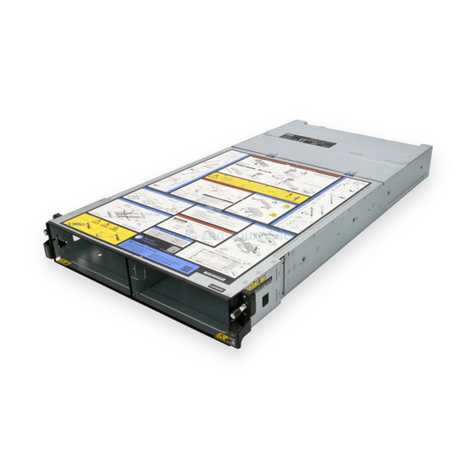
Lenovo SE350 User manual

ThinkSystem SE350 and ThinkSystem SE350
Enclosures
Maintenance Manual
Machine Types: 7Z46, 7D1 , 7D27, and 7D1R

Note
Before using this information and the product it supports, be sure to read and understand the safety
information and the safety instructions, which are available at:
http://thinksystem.lenovofiles.com/help/topic/safety_documentation/pdf_files.html
In addition, be sure that you are familiar with the terms and conditions of the Lenovo warranty for your server,
which can be found at:
http://datacentersupport.lenovo.com/warrantylookup
Thirty-fourth Edition (November 2022)
© Copyri ht Lenovo 2019, 2022.
LIMITED AND RESTRICTED RIGHTS NOTICE: If data or software is delivered pursuant to a General Services
Administration (GSA) contract, use, reproduction, or disclosure is subject to restrictions set forth in Contract No. GS-35F-
05925.

Contents
Contents . . . . . . . . . . . . . . . . . i
Safety . . . . . . . . . . . . . . . . . . iii
Safety inspection checklist . . . . . . . . . . . iv
Chapter 1. Introduction . . . . . . . . . 1
Specifications . . . . . . . . . . . . . . . . 1
Shock and vibration specifications . . . . . 10
Particulate contamination . . . . . . . . . 10
Firmware updates . . . . . . . . . . . . . . 11
Tech Tips . . . . . . . . . . . . . . . . . 15
Security advisories . . . . . . . . . . . . . 15
Power on the server . . . . . . . . . . . . . 16
Power off the server . . . . . . . . . . . . . 16
Chapter 2. Server components . . . . 17
Front view . . . . . . . . . . . . . . . . . 18
Front operator panel . . . . . . . . . . . 20
Rear view . . . . . . . . . . . . . . . . . 21
System-board switches, jumpers, and buttons. . . 23
System-board LEDs . . . . . . . . . . . 23
System-board connectors . . . . . . . . . 23
LOM packages . . . . . . . . . . . . . 24
System-board switches and jumpers. . . . . 26
PCIe riser assembly . . . . . . . . . . . . . 27
M.2 drive and slot numbering . . . . . . . . . 28
Parts list. . . . . . . . . . . . . . . . . . 30
Power cords . . . . . . . . . . . . . . 35
Chapter 3. Hardware replacement
procedures . . . . . . . . . . . . . . . 37
Installation Guidelines . . . . . . . . . . . . 37
System reliability guidelines . . . . . . . . 38
Working inside the server with the power on . . 39
Handling static-sensitive devices . . . . . . 39
Adapter replacement. . . . . . . . . . . . . 39
Remove the M.2 boot adapter . . . . . . . 39
Install the M.2 boot adapter . . . . . . . . 40
Remove the M.2 WLAN/LTE wireless
adapter . . . . . . . . . . . . . . . . 41
Install the M.2 WLAN/LTE wireless adapter . . 42
Remove a M.2 data adapter . . . . . . . . 43
Install a M.2 data adapter . . . . . . . . . 45
Remove the PCIe adapter . . . . . . . . . 47
Install the PCIe adapter . . . . . . . . . . 49
Air baffle replacement . . . . . . . . . . . . 50
Remove the air baffle . . . . . . . . . . . 50
Install the air baffle . . . . . . . . . . . . 51
CMOS battery (CR2032) replacement . . . . . . 52
Remove the CMOS battery (CR2032) . . . . 52
Install the CMOS battery (CR2032) . . . . . 55
DIMM replacement . . . . . . . . . . . . . 57
Remove a DIMM. . . . . . . . . . . . . 57
Install a DIMM . . . . . . . . . . . . . 59
Dust filter replacement . . . . . . . . . . . . 60
Remove the dust filter in locking bezel . . . . 60
Install the dust filter in locking bezel . . . . . 61
Remove the dust filter in E1 enclosure
bracket . . . . . . . . . . . . . . . . 62
Install the dust filter in E1 enclosure bracket . . 63
Fan replacement . . . . . . . . . . . . . . 64
Remove a fan . . . . . . . . . . . . . . 64
Install a fan . . . . . . . . . . . . . . . 65
Front operator panel replacement. . . . . . . . 67
Remove the front operator panel . . . . . . 67
Install the front operator panel . . . . . . . 68
Heat sink replacement . . . . . . . . . . . . 69
Remove the heat sink. . . . . . . . . . . 69
Install the heat sink. . . . . . . . . . . . 71
Intrusion switch cable replacement . . . . . . . 72
Remove the intrusion switch cable . . . . . 72
Install the intrusion switch cable . . . . . . 73
Lock position switch replacement. . . . . . . . 75
Remove the lock position switch . . . . . . 75
Install the lock position switch . . . . . . . 77
LTE/WLAN Antenna replacement . . . . . . . . 78
Remove a LTE/WLAN Antenna . . . . . . . 78
Install a LTE/WLAN Antenna . . . . . . . . 79
M.2 drive on an M.2 data adapter replacement. . . 80
Remove an M.2 drive from an M.2 data
adapter . . . . . . . . . . . . . . . . 80
Install an M.2 drive on an M.2 data adapter . . 81
M.2 LTE module replacement . . . . . . . . . 82
Remove the M.2 LTE module . . . . . . . . 82
Install the M.2 LTE module. . . . . . . . . 85
M.2 WLAN module replacement . . . . . . . . 91
Remove the M.2 WLAN module . . . . . . . 91
Install the M.2 WLAN module. . . . . . . . 94
Node replacement. . . . . . . . . . . . . . 98
Remove a node . . . . . . . . . . . . . 98
Install a node . . . . . . . . . . . . . . 101
PCIe riser assembly replacement . . . . . . . . 103
Remove the PCIe riser assembly . . . . . . 103
© Copyright Lenovo 2019, 2022 i
Install the PCIe riser assembly . . . . . . . 106
Power distribution module replacement . . . . . 108
Remove the power distribution module . . . . 108
Install the power distribution module . . . . . 109
Power adapter replacement . . . . . . . . . . 110
Remove a power adapter . . . . . . . . . 110
Install a power adapter . . . . . . . . . . 114
Rubber feet replacement . . . . . . . . . . . 119
Remove the rubber feet . . . . . . . . . . 119
Install the rubber feet . . . . . . . . . . . 120
SIM card replacement . . . . . . . . . . . . 121
Remove the SIM card. . . . . . . . . . . 121
Install the SIM card. . . . . . . . . . . . 122
System board replacement . . . . . . . . . . 124
Remove the system board assembly . . . . . 124
Install the system board assembly. . . . . . 128
Update the machine type and serial
number . . . . . . . . . . . . . . . . 134
Enable TPM . . . . . . . . . . . . . . 136
Enable UEFI Secure Boot . . . . . . . . . 138
Change the VPD for E1 Enclosure
configuration (trained technician only) . . . . 139
Top cover replacement . . . . . . . . . . . . 140
Remove the top cover . . . . . . . . . . 140
Install the top cover . . . . . . . . . . . 141
TPM card (for Chinese Mainland only)
replacement . . . . . . . . . . . . . . . . 143
Remove the TPM card (for Chinese Mainland
only) . . . . . . . . . . . . . . . . . 143
Install the TPM card (for Chinese Mainland
only) . . . . . . . . . . . . . . . . . 144
Complete the parts replacement . . . . . . . . 145
Chapter 4. Problem
determination . . . . . . . . . . . . . 147
Event logs . . . . . . . . . . . . . . . . . 147
The front operator panel and error LEDs . . . . . 149
System-board LEDs . . . . . . . . . . . 150
General problem determination procedures . . . . 150
Resolving suspected power problems . . . . 151
Resolving suspected Ethernet controller
problems . . . . . . . . . . . . . . . 151
Troubleshooting by symptom . . . . . . . . . 152
Power on and power off problems . . . . . . 152
Memory problems . . . . . . . . . . . . 154
Monitor and video problems . . . . . . . . 155
Keyboard, mouse, KVM switch or USB-device
problems . . . . . . . . . . . . . . . 156
Optional-device problems . . . . . . . . . 157
Serial-device problems . . . . . . . . . . 159
Intermittent problems. . . . . . . . . . . 160
Power problems . . . . . . . . . . . . . 161
Network problems . . . . . . . . . . . . 161
Observable problems. . . . . . . . . . . 168
Software problems. . . . . . . . . . . . 171
SIM selection and APN settings (Japan) . . . 171
Appendix A. Gettin help and
technical assistance . . . . . . . . . . 175
Before you call . . . . . . . . . . . . . . . 175
Collecting service data . . . . . . . . . . . . 176
Contacting Support . . . . . . . . . . . . . 177
Appendix B. Notices. . . . . . . . . . 179
Trademarks . . . . . . . . . . . . . . . . 180
Important notes . . . . . . . . . . . . . . . 180
Telecommunication regulatory statement. . . . . 180
Electronic emission notices . . . . . . . . . . 181
Taiwan Region BSMI RoHS declaration. . . . 181
Taiwan Region import and export contact
information . . . . . . . . . . . . . . . . 181
Index . . . . . . . . . . . . . . . . . . 183
ii ThinkSystem SE350 and ThinkSystem SE350 Enclosures Maintenance Manual

Safety
Before installing this product, read the Safety Information.
Antes de instalar este produto, leia as Informações de Segurança.
在安装本产品之前,请仔细阅读 Safety Information (安全信息)。
Læs sikkerhedsforskrifterne, før du installerer dette produkt.
Lees voordat u dit product installeert eerst de veiligheidsvoorschriften.
Ennen kuin asennat tämän tuotteen, lue turvaohjeet kohdasta Safety Information.
Avant d'installer ce produit, lisez les consignes de sécurité.
Vor der Installation dieses Produkts die Sicherheitshinweise lesen.
Prima di installare questo prodotto, leggere le Informazioni sulla Sicurezza.
Les sikkerhetsinformasjonen (Safety Information) før du installerer dette produktet.
Antes de instalar este produto, leia as Informações sobre Segurança.
© Copyright Lenovo 2019, 2022 iii

Antes de instalar este producto, lea la información de seguridad.
Läs säkerhetsinformationen innan du installerar den här produkten.
Safety inspection checklist
Use the information in this section to identify potentially unsafe conditions with your server. As each machine
was designed and built, required safety items were installed to protect users and service technicians from
injury.
Notes:
1. The product is not suitable for use at visual display workplaces according to §2 of the Workplace
Regulations.
2. The set-up of the server is made in the server room only.
CAUTION:
This equipment must be installed or serviced by trained personnel, as defined by the NEC, IEC 62368-
1 & IEC 60950-1, the standard for Safety of Electronic Equipment within the Field of Audio/Video,
Information Technolo y and Communication Technolo y. Lenovo assumes you are qualified in the
servicin of equipment and trained in reco nizin hazards ener y levels in products. Access to the
equipment is by the use of a tool, lock and key, or other means of security, and is controlled by the
authority responsible for the location.
Important: Electrical grounding of the server is required for operator safety and correct system function.
Proper grounding of the electrical outlet can be verified by a certified electrician.
Use the following checklist to verify that there are no potentially unsafe conditions:
1. Make sure that the power is off and the power cord is disconnected.
2. Check the power cord.
• Make sure that the third-wire ground connector is in good condition. Use a meter to measure third-
wire ground continuity for 0.1 ohm or less between the external ground pin and the frame ground.
• Make sure that the power cord is the correct type.
To view the power cords that are available for the server:
a. Go to:
iv ThinkSystem SE350 and ThinkSystem SE350 Enclosures Maintenance Manual

http://dcsc.lenovo.com/#/
b. Click Preconfi ured Model or Confi ure to order.
c. Enter the machine type and model for your server to display the configurator page.
d. Click Power ➙ Power Cables to see all line cords.
• Make sure that the insulation is not frayed or worn.
3. Check for any obvious non-Lenovo alterations. Use good judgment as to the safety of any non-Lenovo
alterations.
4. Check inside the server for any obvious unsafe conditions, such as metal filings, contamination, water or
other liquid, or signs of fire or smoke damage.
5. Check for worn, frayed, or pinched cables.
6. Make sure that the power-supply cover fasteners (screws or rivets) have not been removed or tampered
with.
© Copyright Lenovo 2019, 2022 v

vi ThinkSystem SE350 and ThinkSystem SE350 Enclosures Maintenance Manual

Chapter 1. Introduction
The ThinkSystem SE350 server is a new edge server offering. It is specifically designed to meet the needs at
IoT and edge locations. The ThinkSystem SE350 is a compact sized edge solution with a focus on smart
connectivity, business security and manageability for the harsh environment. Built for long life and
dependable performance to support your demanding IoT workloads at the Edge. Compact it is designed for
the non-datacenter environment, ideal for remote locations such as retail, manufacturing and factory
locations.
Note: SE350 with Security Pack is also known simply as SE350 prior to July 2021.
Figure 1. ThinkSystem SE350
The server comes with a limited warranty. For details about the warranty, see:
https://support.lenovo.com/us/en/solutions/ht503310
For details about your specific warranty, see:
http://datacentersupport.lenovo.com/warrantylookup
Specifications
The following information is a summary of the features and specifications of the server. Depending on the
model, some features might not be available, or some specifications might not apply.
© Copyright Lenovo 2019, 2022 1

Table 1. Server Specificati ns
Specification Description
Security option (depending on
the model) • SE350 with Security Pack
– SE350 automatic data protection, including intrusion sensor and motion
sensor, can be enabled.
– SED data access can be locked up at tamper events.
– The system will need to be claimed and activated in order to unlock and access
data.
– Requires activation to boot up and fully functional.
• SE350 Standard (Security Pack disabled)
– SE350 automatic data protection, including intrusion sensor and motion
sensor, is disabled.
– Data access will never be locked up. SED management is disabled. Tamper
setting is disabled.
– No activation is required.
– Claiming the system is optional. Secure Activation Code is needed for claiming.
Notes:
• SE350 with Security Pack is also known simply as SE350 prior to July 2021.
• You can check whether your system is SE350 with Security Pack or SE350
Standard in Lenovo Clarity Controller.
Size Node
• Height: 43.2 mm (1.7 inches)
• Width: 209 mm (8.2 inches)
• Depth: 376.1 mm (14.8 inches)
E1 Enclosure (1U 2-node):
• Height: 43 mm (1.69 inches)
• Width: 439.2 mm (17.29 inches, from EIA bracket to EIA bracket)
• Depth: 773.12 mm (30.44 inches)
• Weight: 10 kg (with 1 node and 2 power adapters), 15 kg (with 4 power adapters)
E2 Enclosure (2U 2-node):
• Height: 86.9 mm (3.42 inches)
• Width: 439.2 mm (17.29 inches, from EIA bracket to EIA bracket)
• Depth: 476.12 mm (18.74 inches)
• Weight: 10 kg (with 1 node and 2 power adapters), 15 kg (with 4 power adapters)
Weight Node
• Maximum: 3.6 kg (7.9 lbs)
Processor (depending on the
model)
One Intel® eon® processor D-2100 product family
Notes:
1. Use the Setup utility to determine the type and speed of the processors in the
node.
2. For a list of supported processors, see https://serverproven.lenovo.com/server/
se350.
2ThinkSystem SE350 and ThinkSystem SE350 Enclosures Maintenance Manual

Table 1. Server Specificati ns (c ntinued)
Specification Description
Memory See “Memory module installation order” in Setup Guide for detailed information
about memory configuration and setup.
• Slots: 4 DIMM slots
• Minimum: 8 GB (1 x 8GB RDIMM)
• Maximum: 256 GB (4 x 64GB LRDIMM)
• Type:
– PC4-21300 (single-rank, dual-rank), 2666 MT/s, error correcting code (ECC),
double-data-rate 4 (DDR4) registered DIMM (RDIMM)
– PC4-21300 (quad-rank), 2666 MT/s, error correcting code (ECC), double-data-
rate 4 (DDR4) load reduced DIMM (LRDIMM)
Note: For a list of supported processors, see https://serverproven.lenovo.com/server/
se350.
M.2 drive M.2 boot adapter
• Supports up to two identical M.2 SATA drives
• Supports three different physical sizes of M.2 drives:
– 42 mm (2242)
– 60 mm (2260)
– 80 mm (2280)
M.2 data adapter
• PCIe and M.2 riser assembly:
– Supports up to four M.2 SATA/NVMe drives
• M.2 riser assembly
– Supports up to eight M.2 NVMe drives
– Supports up to four NVMe and four SATA drives
• Supports four different physical sizes of M.2 drives:
– 42 mm (2242)
– 60 mm (2260)
– 80 mm (2280)
– 110 mm (22110)
Notes:
• M.2 drives installed on boot adapter and on data adapter are not swappable.
• M.2 connector type: socket 3 (M key)
• Mixing SATA drives and NVMe drives in the same M.2 SATA/NVMe 4-bay data
adapter is not supported.
PCIe riser assembly PCIe and M.2 riser assembly:
• Slot 6: PCI Express 3.0 x16, (supports <75W, low profile, half-height, half-length
PCIe adapter)
Chapter 1.Introduction 3

Table 1. Server Specificati ns (c ntinued)
Specification Description
WLAN • WLAN: IEEE 802.11 a/b/g/n/ac
• MIMO: 2x2 MIMO
• Interfaces: WLAN: PCIe x1
• Antenna configuration: 2xIPE (MHF4) connector
• Form factor: M.2 2230
• Maximum number of concurrent user connection (AP mode): eight
• Security:
– AP mode supports WPA2 Personal
– Station mode supports both WPA2 Enterprise and Personal
• Working Band:
– AP Mode: 2.4GHz
– Station Mode: 2.4GHz/5GHz
Notes:
• WLAN performance may vary depending on your configuration and environment.
• Wireless signal quality may be affected when installed in a rack or cabinet.
LTE • 3GPP Release 11
• Category: Cat9
• Region: Global
• Operating mode: FDD/TDD
• Data transmission: up to 450Mbps DL/50Mbps UL
• Function interface: USB 3.0
• Antenna configuration: 2xIPE (MHF4) connector
• Form factor: M.2 3042
Notes:
• LTE performance may vary depending on your configuration and environment.
• Wireless signal quality may be affected when installed in a rack or cabinet.
4ThinkSystem SE350 and ThinkSystem SE350 Enclosures Maintenance Manual

Table 1. Server Specificati ns (c ntinued)
Specification Description
Integrated functions • Lenovo Clarity Controller, which provides service processor control and
monitoring functions, video controller, and remote keyboard, video, mouse, and
remote drive capabilities.
• Front operator panel
• LOM module connector (front of server):
– 10G SFP+ LOM Package
– Two USB 3.1 Gen 1 connectors
– Two 1Gb Ethernet connectors
– Two Lenovo Clarity Controller network connectors
– Two 10Gb SFP+ connectors
– One VGA connector
– Wireless enabled LOM Package
– Two USB 3.1 Gen 1 connectors
– Two 1Gb Ethernet connectors
– One Lenovo Clarity Controller network connector
– Two 1Gb SFP connectors
– Two 10Gb SFP+ connectors
– One VGA connector
– 10G BASE-T LOM Package
– Two Lenovo Clarity Controller network connector
– Two 10Gb BASE-T RJ45 connectors
– Two 1Gb Ethernet connectors
– Two USB 3.1 Gen 1 connectors
– One VGA connector
• Rear I/O connectors (rear of server):
– Two WLAN Antenna connectors
– One RS-232 port (RJ-45)
– Two LTE Antenna connectors
– Two USB 2.0 connectors
– Two types of power distribution module:
– 12V power distribution module (PDM) with two power connectors
– -48V power distribution module (PDM) with one power connector
RAID controllers Software RAID: A software RAID controller is integrated on the system board,
supporting RAID levels 0, 1, 5, and 10.
• Supports standard Intel SATA software RAID, RSTe
• Supports Intel VROC NVMe RAID
– VROC Intel-SSD-Only supports RAID levels 0, 1, 5, and 10 with Intel NVMe
drives.
– VROC Premium requires an activation key and supports RAID levels 0, 1, 5, and
10 with non-Intel NVMe drives. For more information about acquiring and
installing the activation key, see https://fod.lenovo.com/lkms.
Chapter 1.Introduction 5

Table 1. Server Specificati ns (c ntinued)
Specification Description
Hardware RAID: An M.2 hardware RAID module is needed for hardware RAID
storage, supporting RAID levels 0 and 1.
Video controller (integrated
into Lenovo Clarity
Controller)
Matrox G200
• ASPEED
• SVGA compatible video controller
• Avocent Digital Video Compression
• 16 MB of video memory (not expandable)
Note: Maximum video resolution is 1920 x 1200 at 60 Hz.
Fans Three 40 mm system fans
Power adapters External power adapters:
Sine-wave input (50–60 Hz) required
• 240W external power adapter
100-127 V ac / 200-240 V ac, 3.2/1.6 A
Notes:
• Power adapters is supported only by 12V PDM
CAUTION:
– Power adapters to the node must be with the same brand, power ratin ,
watta e or efficiency level.
– To distin uish the power adapters, check the size, the position of
connector, and the label of the power adapters.
• When GPU is installed, system must be installed with two power adapters
EU ErP (EcoDesign) Directive (2009/125/EC) Implementing Measure (COMMISSION
REGULATION (EU) 2019/1782 of 1 October 2019) requires manufacturers to provide
the energy efficiency and rating information. Lenovo products are designed to work
with a range of compatible chargers and different chargers may be shipped in box or
purchased subsequently. A list of suitable chargers can be found on the EU
Declaration of Conformity (DoC) accessible here (https://www.lenovo.com/us/en/
compliance/eu-doc). In order to access the applicable energy efficiency information
for your charger, please access the following web page, search for your product
using the full model number and select the applicable user guide or power supply
data sheet. https://support.lenovo.com/
6ThinkSystem SE350 and ThinkSystem SE350 Enclosures Maintenance Manual

Table 1. Server Specificati ns (c ntinued)
Specification Description
Acoustical noise emissions
(base configuration) • Operation:
– Minimum: 5.3 bels
– Typical: 5.4 bels
– Maximum: 5.7 bels
• Idle
– Minimum: 4.9 bels
– Typical: 5.0 bels
– Maximum: 5.4 bels
Notes:
1. These sound power levels are measured in controlled acoustical environments
according to procedures specified by ISO 7779 and are reported in accordance
with ISO 9296.
2. The declared acoustic noise levels are based on specified configurations, which
may change slightly depending on configurations/conditions.
3. The options supported in this server vary in function, power consumption, and
required cooling. Any increase in cooling required by these options will increase
the fan speed and generated sound level. The actual sound pressure levels
measured in your installation depend upon a variety of factors, including: the
number of racks in the installation; the size, materials, and configuration of the
room; the noise levels of other equipment; the room ambient temperature and
barometric pressure; and the location of employees in relation to the equipment.
Heat output Approximate heat output:
• Minimum configuration: 287.46 BTU per hour (84.25 watts)
• Maximum configuration : 783.02 BTU per hour (229.49 watts)
Electrical input Power distribution module: 12V PDM
• Supports 12.2V/20A per power adapter
• Each node supports up to two power adapters
Power distribution module: -48V PDM
• -48V - -60V DC / 8.4 A max direct -48V input
Notes:
• Power redundancy is in dual power mode when system power consumption is
under 210W.
• System operates in capping/throttling mode when power resource is insufficient.
• Install two power adapters when system power consumption is higher than 210W.
Chapter 1.Introduction 7

Table 1. Server Specificati ns (c ntinued)
Specification Description
Cautions and regulatory
compliance statements for
NEBS
Follow NEBS GR-1089-CORE cautions, regulatory compliance statements, and
requirements.
• Supports Common Bonding Network (CBN) installation.
• System can be installed in network telecommunication facilities where the
National Electric Code applies.
• It is required to turn ON UEFI “Power Restore Policy” when set the test condition
in “MIN OPERATING VOLTAGE ”
• The 1Gb Ethernet and SFP+ cables evaluated by NEBS measurement are required
shielded.
• The typical system boot up time under NEBS section 4 evaluation is 4 minutes and
55 seconds.
• WARNING: The intra-building port(s) (1Gb Ethernet and SFP+ ports) of the
equipment or subassembly is suitable for connection to intra-building or
unexposed wiring or cabling only. The intra-building port(s) of the equipment or
subassembly MUST NOT be metallically connected to interfaces that connect to
the OSP or its wiring for more than 6 meters (approximately 20 feet). These
interfaces are designed for use as intra-building interfaces only (Type 2 port as
described in GR-1089) and require isolation from the exposed OSP cabling. The
addition of Primary Protectors is not sufficient protection in order to connect these
interfaces metallically to an OSP wiring system.
Environment The ThinkSystem SE350 complies with ASHRAE class A4 specifications. System
performance may be impacted when operating temperature is outside ASHRAE A4
Specification or fan failed condition outside A2 Specification.
The ThinkSystem SE350 is supported in the following environment:
• Standard:
– Server on: 0°C to 45°C (32°F to 113°F)
– Server off: 0°C to 45°C (32°F to 113°F)
• ASHRAE Class A4
– Server on: 5°C to 45°C (41°F to 113°F); decrease the maximum ambient
temperature by 1°C for every 125 m (410 ft) increase in altitude above 900 m
(2,953 ft).
– Sever off: 5°C to 45°C (41°F to 113°F)
• Extended operation temperature (with limited configuration1):
– Server on: 0°C to 55°C (32°F to 131°F)
– Server off: 0°C to 55°C (32°F to 131 °F)
Notes: Limited configuration1:
– No GPU
– No Micron/LITE-ON M.2
– Only Lenovo certified PCIe cards, for example:
• ThinkSystem Broadcom N -E PCIe 10Gb 2-Port Base-T Ethernet Adapter
• ThinkSystem Mellanox Connect -4 Lx 10/25GbE SFP28 2-port PCIe
Ethernet Adapter
• Shipping/storage: -40 to 60°C (-40 to 140°F)
• Maximum altitude: 3050 m (10 000 ft)
8ThinkSystem SE350 and ThinkSystem SE350 Enclosures Maintenance Manual

Table 1. Server Specificati ns (c ntinued)
Specification Description
• Relative Humidity (non-condensing):
– Operating: 8% to 90%, maximum dew point : 24°C (75.2°F)
– Shipment/storage: 8% to 90%, maximum dew point : 27°C (80.6°F)
• Non-operating (unpacked) storage can pass the following condition: 5% to 95% at
38.7°C (101.7°F) maximum dry-bulb temperature for 48 hrs.
• Particulate contamination
Attention: Airborne particulates and reactive gases acting alone or in
combination with other environmental factors such as humidity or temperature
might pose a risk to the server. For information about the limits for particulates and
gases, see “Particulate contamination” on page 10.
Operating systems
Supported and certified operating systems:
• Microsoft Windows Server
• VMware ES i
• Red Hat Enterprise Linux
• SUSE Linux Enterprise Server
References:
• Complete list of available operating systems: https://lenovopress.com/osig.
• OS deployment instructions: See “Deploy the operating system” in Setup Guide..
Chapter 1.Introduction 9

Shock and vibration specifications
The following information is a summary of the shock and vibration specifications of the server. Depending on
the model, some features might not be available, or some specifications might not apply.
SE350 system configuration Vibration
(when server
is in operation)
Shock
(when server
is in operation)
Environmental vibration criteria
Left wing Right wing IEC Stationary
0.15Grms,
30mins15G,
11ms
3.06 Grms,
15mins 30G,
11ms
3.06 Grms,
60mins 30G,
11ms
Four M.2
SATA drives
None 3.06Grms,
3-500 Hz, 60
min/axis
30G, 11ms,
half-sine, ± ,
±Y, ±Z
√ √ √
Four M.2
SATA drives
NVIDIA T4
GPU 3.06Grms,
3-500 Hz, 15
min/axis
30G, 11ms,
half-sine, ± ,
±Y, ±Z
√ √
Four M.2
NVMe drives
(with heatsink)
Four M.2
NVMe drives
(with heatsink)
0.21Grms, 5-
500 Hz, 15
min/axis
15G, 3ms,
half-sine, ± ,
±Y, ±Z
√
Four M.2
NVMe drives
(with heatsink)
NVIDIA T4
GPU 0.21Grms,
5-500 Hz, 15
min/axis
15G, 3ms,
half-sine, ± ,
±Y, ±Z
√
Particulate contamination
Attention: Airborne particulates (including metal flakes or particles) and reactive gases acting alone or in
combination with other environmental factors such as humidity or temperature might pose a risk to the
device that is described in this document.
Risks that are posed by the presence of excessive particulate levels or concentrations of harmful gases
include damage that might cause the device to malfunction or cease functioning altogether. This
specification sets forth limits for particulates and gases that are intended to avoid such damage. The limits
must not be viewed or used as definitive limits, because numerous other factors, such as temperature or
moisture content of the air, can influence the impact of particulates or environmental corrosives and gaseous
contaminant transfer. In the absence of specific limits that are set forth in this document, you must
implement practices that maintain particulate and gas levels that are consistent with the protection of human
health and safety. If Lenovo determines that the levels of particulates or gases in your environment have
caused damage to the device, Lenovo may condition provision of repair or replacement of devices or parts
on implementation of appropriate remedial measures to mitigate such environmental contamination.
Implementation of such remedial measures is a customer responsibility.
10 ThinkSystem SE350 and ThinkSystem SE350 Enclosures Maintenance Manual

Table 2. Limits f r particulates and gases
Contaminant Limits
Reactive gases Severity level G1 as per ANSI/ISA 71.04-19851:
• The copper reactivity level shall be less than 200 Angstroms per month (Å/month ≈ 0.0035 μg/
cm2-hour weight gain).2
• The silver reactivity level shall be less than 200 Angstroms per month (Å/month ≈ 0.0035 μg/
cm2-hour weight gain).3
• The reactive monitoring of gaseous corrosivity must be conducted approximately 5 cm (2 in.) in
front of the rack on the air inlet side at one-quarter and three-quarter frame height off the floor
or where the air velocity is much higher.
Airborne
particulates Data centers must meet the cleanliness level of ISO 14644-1 class 8.
For data centers without airside economizer, the ISO 14644-1 class 8 cleanliness might be met by
choosing one of the following filtration methods:
• The room air might be continuously filtered with MERV 8 filters.
• Air entering a data center might be filtered with MERV 11 or preferably MERV 13 filters.
For data centers with airside economizers, the choice of filters to achieve ISO class 8 cleanliness
depends on the specific conditions present at that data center.
• The deliquescent relative humidity of the particulate contamination should be more than 60%
RH.4
• Data centers must be free of zinc whiskers.5
1 ANSI/ISA-71.04-1985. Envir nmental c nditi ns f r pr cess measurement and c ntr l systems: Airb rne
c ntaminants. Instrument Society of America, Research Triangle Park, North Carolina, U.S.A.
2 The derivation of the equivalence between the rate of copper corrosion growth in the thickness of the corrosion
product in Å/month and the rate of weight gain assumes that Cu2S and Cu2O grow in equal proportions.
3 The derivation of the equivalence between the rate of silver corrosion growth in the thickness of the corrosion
product in Å/month and the rate of weight gain assumes that Ag2S is the only corrosion product.
4 The deliquescent relative humidity of particulate contamination is the relative humidity at which the dust absorbs
enough water to become wet and promote ionic conduction.
5 Surface debris is randomly collected from 10 areas of the data center on a 1.5 cm diameter disk of sticky
electrically conductive tape on a metal stub. If examination of the sticky tape in a scanning electron microscope
reveals no zinc whiskers, the data center is considered free of zinc whiskers.
Firmware updates
Several options are available to update the firmware for the server.
You can use the tools listed here to update the most current firmware for your server and the devices that are
installed in the server.
• Best practices related to updating firmware is available at the following site:
– http://lenovopress.com/LP0656
• The latest firmware can be found at the following site:
– https://datacentersupport.lenovo.com/products/servers/thinksystem/se350/downloads
• You can subscribe to product notification to stay up to date on firmware updates:
– https://datacentersupport.lenovo.com/tw/en/solutions/ht509500
Chapter 1.Introduction 11

UpdateXpress System Packs (UXSPs)
Lenovo typically releases firmware in bundles called Update press System Packs (U SPs). To ensure that all
of the firmware updates are compatible, you should update all firmware at the same time. If you are updating
firmware for both the Lenovo Clarity Controller and UEFI, update the firmware for Lenovo Clarity Controller
first.
Update method terminolo y
• In-band update. The installation or update is performed using a tool or application within an operating
system that is executing on the server’s core CPU.
• Out-of-band update. The installation or update is performed by the Lenovo Clarity Controller collecting
the update and then directing the update to the target subsystem or device. Out-of-band updates have no
dependency on an operating system executing on the core CPU. However, most out-of-band operations
do require the server to be in the S0 (Working) power state.
• On-Tar et update. The installation or update is initiated from an installed operating system executing on
the target server itself.
• Off-Tar et update. The installation or update is initiated from a computing device interacting directly with
the server’s Lenovo Clarity Controller.
• UpdateXpress System Packs (UXSPs). U SPs are bundled updates designed and tested to provide the
interdependent level of functionality, performance, and compatibility. U SPs are server machine-type
specific and are built (with firmware and device driver updates) to support specific Windows Server, Red
Hat Enterprise Linux (RHEL) and SUSE Linux Enterprise Server (SLES) operating system distributions.
Machine-type-specific firmware-only U SPs are also available.
Firmware updatin tools
See the following table to determine the best Lenovo tool to use for installing and setting up the firmware:
Tool
Update
Methods
Suppor-
ted
Core
System
Firmware
Updates
I/O
Devices
Firm-
ware
Updates
Graphi-
cal user
interface
Com-
mand
line
interface
Supports
UXSPs
Lenovo XClarity Provisionin Mana er
(LXPM)
In-band2
On-
Target
√ √
Lenovo XClarity Controller
(XCC)
Out-of-
band
Off-
Target
√Selected
I/O
devices
√
Lenovo XClarity Essentials OneCLI
(OneCLI)
In-band
Out-of-
band
On-
Target
Off-
Target
√All I/O
devices
√ √
12 ThinkSystem SE350 and ThinkSystem SE350 Enclosures Maintenance Manual
Other manuals for SE350
4
Table of contents
Other Lenovo Enclosure manuals

Lenovo
Lenovo ThinkAgile VX3720 7Y12 User manual

Lenovo
Lenovo ThinkSystem DW612S Neptune DWC User manual

Lenovo
Lenovo ideacentre 510 Series Owner's manual

Lenovo
Lenovo NeXtScale n1200 Installation and maintenance instructions

Lenovo
Lenovo Legion BoostStation 82CA000GGE User manual

Lenovo
Lenovo ThinkSystem D2 User manual

Lenovo
Lenovo ThinkSystem E2 User manual

Lenovo
Lenovo S3200 User manual

Lenovo
Lenovo E1012 User manual

Lenovo
Lenovo ThinkSystem DW612S Neptune DWC User manual