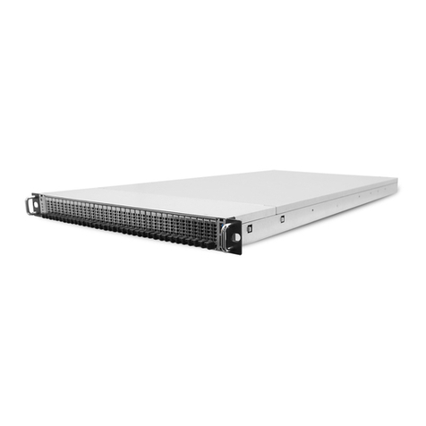
Lenovo ThinkSystem D4390 Operating manual

Lenovo ThinkSystem
D4390 Direct Attached Storage
Hardware Installation and Maintenance Guide
Machine Type: 7DAH

i
Note:
Before using this information and the product it supports, read the information in Notices
.
Second Edition (May 2023)
© Copyright Lenovo 2023.
LIMITED AND RESTRICTED RIGHTS NOTICE: If data or software is delivered pursuant to a General Services Administration (GSA) contract,
use, reproduction, or disclosure is subject to restrictions set forth in Contract No. GS-35F-0592

ii
About this Guide
This guide provides information about initial hardware setup, removal, and installation of field-replaceable units
(FRUs) for the Lenovo ThinkSystem D4390 Direct Attached Storage enclosure.
Intended audience
System administrators
Storage administrators
Convention
Icon or Format Instruction
NOTE: Indicates important information that helps you make better use of your
system
CAUTION: There is a risk of personal injury and equipment damage. Follow the
instructions.
CAUTION: Hot surface. Avoid contact. Surfaces are hot and may cause personal
injury if touched.
CAUTION: Hazardous voltages are present. To reduce the risk of electric shock
and danger to personal health, follow the instructions.
WARNING: Indicates a potential for property damage, personal injury, or death.
italics Book or document name.
Fill in the content.
> Menu links at all levels
Bold Menu, Button, Options
Regulatory Compliance
EMC Compliance
●EN 55032 (2015), CISPR-32 (2015) Class A
●EN 61000-3-2 (2014)
●EN 61000-3-3 (2013)
●EN 55024:2010+A1:2015/EN55035:2017
●FCC 47 CFR Part 15 Class A
●VCCI V-3 2016 Class A
●ICES-003, Issue7: 2020 Class A

iii
Safety Compliance
●UL 60950-1, 2nd Edition, 2014-10-14
●CAN/CSA C22.2 No. 60950-1-07, 2nd Edition, 2014-10
●UL 62368-1, 2nd Ed, 2014-12-01
●CAN/CSA C22.2 No. 62368-1-14, 2nd Ed, Issued: 2014-12-01
●IEC 60950-1 2012 A2-2013
●EN 60950-1/A12:2011 A2:2013
●IEC 62368-1:2014
●EN 62368-1:2014/A11:2017
●IEC 62368-1:2018/EN
●EN 62368-1:2020+A11:2020
Environmental Specification
Temperature and Temperature Gradient
Operating Ambient Temperature 5 to 35ºC
Max Temperature Gradient 20ºC per hour
Non-Operating Ambient Non-Operating -40 to 60 ºC
Humidity
Operating Ambient Operating (Non-condensing) 8 to 85 % R.H
Non-Operating Ambient Non-Operating (Non-condensing) 8 to 95 % R.H
Altitude
Operating
3050m (support for up to 3050m requires temperature de-rating) [950m@ 35℃,
3050m@ 28℃]
NOTE: De-rate max operating temperature 1℃/300m above 950m altitude.
Non-Operating Maximum Altitude of 12,000 meters (39,370 feet)
Acoustic Noise Specification
A single enclosure shall not exceed 7.6 Bels LwAd (A-Weighted sound power level) at 23+/-2 degree C with
typical system loading.

iv
Acoustic Noise Emissions, Declared Sound Power Level measured in accordance with ISO 7779 and results
reported per ISO 9296.
Cooling Specification
The thermal solution supports drive up to 13W maximum power dissipation per drive slot.
The system shall continue to function normally when the following conditions are met.
●Fan failure:
The System will function normally when one of two fans in the fan module fails.
The maximum time for fan module replacement should not exceed 10 minutes.
●Drive failure:
The cooling system will ensure that the system continues while the top cover is removed for drive failure.
The maximum time for drive replacement should not exceed 10 minutes.
●PSU failure:
The maximum time for PSU replacement should not exceed 10 minutes.

v
Table of Contents
1General Overview............................................................................................................... 1
1.1 Product Appearance .........................................................................................................................................................2
1.2 Product Exploded View.....................................................................................................................................................6
2Storage Enclosure Installation.......................................................................................... 7
2.1 Safety Instructions............................................................................................................................................................7
2.1.1 Safety Precautions....................................................................................................................................................7
2.1.2 Power Cord Connection ............................................................................................................................................7
2.1.3 Electro-Static Discharge (ESD) Caution and Warnings.............................................................................................8
2.1.4 Rack System Instructions..........................................................................................................................................9
2.1.5 Other warnings and cautions.....................................................................................................................................9
2.1.6 Regulatory Information............................................................................................................................................10
2.2 Necessary Tools for Installation ....................................................................................................................................12
2.3 Check the Installation Environment...............................................................................................................................13
2.4 Unpacking........................................................................................................................................................................13
2.5 Rail Kit..............................................................................................................................................................................14
2.5.1 Rail Kit Installation in Lenovo Rack .........................................................................................................................14
2.5.2 Rail Kit Installation in 3rd party rack........................................................................................................................20
2.5.3 Insert the Chassis to Rack.......................................................................................................................................23
2.5.4 Rail Kit Removal (optional if need)..........................................................................................................................25
2.6 CMA Installation with Rail Kit.........................................................................................................................................29
2.7 Drive .................................................................................................................................................................................38
2.7.1 Pull out Chassis from Rack .....................................................................................................................................39
2.7.2 Drive Installation......................................................................................................................................................40
2.7.3 Push Chassis into Rack...........................................................................................................................................45
3Hardware Element Overview............................................................................................46
3.1 ESM (Electronic Service Module) Canister....................................................................................................................46
3.1.1 Overview .................................................................................................................................................................46
3.1.2 ESM Canister LED/Button.......................................................................................................................................46
3.1.3 Mini-SAS HD Port....................................................................................................................................................47

vi
3.1.4 Debug Port..............................................................................................................................................................48
3.1.5 ESM Canister..........................................................................................................................................................48
3.2 PSU-Power Supply Unit..................................................................................................................................................50
3.2.1 Overview .................................................................................................................................................................50
3.2.2 PSU status LED ......................................................................................................................................................50
3.2.3 AC power input and power cord..............................................................................................................................51
3.2.4 PSU Assembly ........................................................................................................................................................51
3.3 Fan Modules.....................................................................................................................................................................52
3.3.1 Overview .................................................................................................................................................................52
3.3.2 Fan Module LED .....................................................................................................................................................53
3.3.3 Fan module Assembly.............................................................................................................................................53
3.4 DC to DC...........................................................................................................................................................................55
3.4.1 DC-DC Installation...................................................................................................................................................56
3.4.2 DC-DC Removal......................................................................................................................................................57
3.5 Drive Carrier.....................................................................................................................................................................57
3.5.1 Drive Carrier Overview............................................................................................................................................57
3.5.2 Drive LED................................................................................................................................................................57
3.5.3 Drive Installation......................................................................................................................................................58
4Cabling and Access to Electricity....................................................................................59
4.1 Connecting and Securing the Power Cable(s)..............................................................................................................59
4.1.1 Connecting the Power Cable(s)...............................................................................................................................59
4.1.2 Securing the Power Cable(s)...................................................................................................................................59
4.2 Connect the enclosure....................................................................................................................................................60
4.3 Self-inspection.................................................................................................................................................................61
5Supported Matrix...............................................................................................................65
5.1 D4390 Storage Enclosure Rules.....................................................................................................................................65
5.2 Supported SAS Host Bus Adapters...............................................................................................................................65
5.3 Supported Physical Disk Drives.....................................................................................................................................65
5.4 Supported Cabling ..........................................................................................................................................................65
5.4.1 SAS HBA Configuration...........................................................................................................................................65
5.4.2 RAID adapter maximum Configuration....................................................................................................................66
vii
6Troubleshooting Your JBOD Enclosure..........................................................................67
6.1 Safety First—For You and Your Enclosure...................................................................................................................67
6.2 Troubleshooting Enclosure Startup Failure..................................................................................................................67
6.3 Troubleshooting Loss of Communication.....................................................................................................................67
6.4 Troubleshooting Power Supply Unit or Cooling Fan Module......................................................................................67
6.5 Troubleshooting Enclosure cooling Problems.............................................................................................................68
6.6 Troubleshooting ESM .....................................................................................................................................................69
6.7 Troubleshooting a Damaged Enclosure........................................................................................................................69
7Contact Information..........................................................................................................71
8Firmware and tools repositories......................................................................................72
9Notices...............................................................................................................................73
9.1 Trademarks......................................................................................................................................................................74

1
1 General Overview
The Lenovo ThinkSystem D4390 Direct Attached Storage is a high availability, 4U high density enterprise-class
JBOD (just a bunch of disks) storage enclosure for up to 90 drives. D4390 supports both 3.5 inch and 2.5 inch
12Gb SAS disk drives and fits within a 1100 mm rack (excluding door space) with cable management.
The PDU location in the rack needs to avoid interference with CMA and FRU removal. Cannister, PSU and DC-
DC modules are removed from the rear of the chassis, so a suitable PDU and the orientation of the power plug
should take these facts into consideration.
●Enclosure
o4U rack-mount storage enclosure with slide rail and cable management assembly
oDimensions (with CMA): 175.3mm (H) × 446mm (W) × 1080mm (D)
oFits in an 1100 mm rack (not including door space) with CMA added
oWeight: 4U assembly with full drive population: 118kg
●Disk Drives
o90 hot-pluggable top-loading drives
oSystem supports 12Gb SAS drives
oUp to 13W per drive slot
●ESM Canister
o4× 24Gb Mini-SAS HD IO ports
oHot-pluggable from rear of chassis
oSupports dual ESM canister system only
oDual redundant ESM canisters with access to all 90 drives
oBased on Broadcom SAS4x48 24Gb SAS Expander
●Power Supply
o2+2 (200-240V) or 3+1 (100-240V) redundant 1300W PSU
oSystem input: 90-264VAC, 47Hz-63Hz via an IEC 320 C-14 power inlet
oHigh efficiency (80Plus Titanium level)
o108A @ 12V and 3.0A @ 12VSB (200-240V)
oHot-pluggable and AC power cord located on rear of chassis
o73.5mm (W) x 40 mm (H) x 185 mm (L)
●Fan module
oFive (5) hot-pluggable, top loading Fan Modules in chassis
oEach fan module contains two 80mm fans (dual-rotor)
oSupports single fan failure

2
1.1 Product Appearance
Figure 1-1 below is the trimetric view of the chassis.
Figure 1-1: D4390 System Trimetric View
Figure 1-2 below is the front view of the chassis.
Figure 1-2: D4390 System Front View

3
Figure 1-3 below is the rear view of the chassis showing PSU, DC-DC modules and ESM canisters.
Figure 1-3: D4390 System Rear View
Figure 1-4 through Figure 1-6 below show the LED information on the D4390 JBOD.
Figure 1-4: D4390 System LEDs

4
System LED
information Description
Drive Fault Summary
LED (Amber) On –At least one drive is faulty in the
enclosure
Off – All drives work fine
Enclosure Power LED
(Green) On – Enclosure power is on
Off – Enclosure power is off
Enclosure Fault LED
(AMBER) On – Fault conditions exist in enclosure
Off – Normal operation
Enclosure Identify LED-
UID (BLUE) Blink – Identifies an enclosure
Off – Normal operation
Table 1-1: D4390 System LED information
Figure 1-5: Fan LEDs on the top of the D4390
Fan LED information Description
~Fan 1~ Fan 5: Fan fault is present
Table 1-2: Fan LED information on the top of the D4390

5
Figure 1-6: Modules on the rear of D4390
Item Description
①PSU1 PSU 1
②PSU2 PSU 2
③DC1 DC-DC Module 1
④ESM1 ESM Canister A
⑤DC2 DC-DC Module 2
⑥PSU3 PSU 3
⑦PSU4 PSU 4
⑧ESM2 ESM Canister B
Table 1-3: Modules on the rear of D4390
Figure 1-7 below is the top view of the chassis showing D4390 drive numbering.

7
2 Storage Enclosure Installation
These instructions are intended to ensure that the user can use the product correctly to avoid danger or property
loss. Please read this Guide carefully before using the product and keep it for future reference. If the product
cannot work normally or is damaged due to not following the safety instructions, Lenovo shall not assume any
responsibility.
CAUTION: Please read the following instructions before the installation.
2.1 Safety Instructions
Read this section before beginning any procedure. It provides safety precautions to follow when installing the
product.
2.1.1 Safety Precautions
For your protection, observe the following safety precautions when setting up your equipment:
●Follow all cautions and instructions marked on the equipment.
●Ensure that the voltage and frequency of your power source match the voltage and frequency inscribed on
the equipment’s electrical rating label.
●Never insert foreign objects of any kind through openings in the equipment. Dangerous voltages, energy or
moving parts may be present. Conductive objects could lead a short circuit that would cause fire, electric
shock or damage to your equipment.
●Do not block or cover the openings of your product. Never place the product near a radiator or heat register.
Failure to follow these guidelines can cause overheating and affect the reliability of your product.
●Do not operate products without the cover in place. Failure to take this precaution may result in system
damage.
●This product is intended for restricted access whereby access is controlled through the use of a means of
security (for example, key, lock, tool, badge access) and the personnel authorized to access have been
asked to follow the safety instructions.
●Do not drop the product or make it subject to physical shock.
●Keep the product away from water or any liquid.
●While shipping the product, pack it inside the qualified package and ship with a pallet.
●The equipment is designed to be used in a data center or lab environment.
2.1.2 Power Cord Connection
Installation of this equipment must comply with local and regional electrical regulations governing the
installation of information technology equipment by licensed electricians. For electrical power ratings on
options, refer to the power rating label or the user documentation supplied with that option.

8
CAUTION: Not all power cords have the same current ratings. Do not use the power cord provided with your
equipment for any other products or use. Do not use household extension cords with your product.
CAUTION: For products with multiple power cords, all power cords must be disconnected to completely remove
power from the system.
For AC power, disconnect all power cords from their AC power source.
Below mark is used when multiple power supplies are installed in a system.
2.1.3 Electro-Static Discharge (ESD) Caution and Warnings
WARNING:
●In order to maximize overall product quality and eliminate the possibility of damage from electro-static
discharge, please observe ESD handling procedures wherever this symbol () is present during the
system integration.
●All Employees must attend an ESD training class prior to performing any system or board handling. If you
have not been properly trained, contact your immediate supervisor to schedule training.
●Required use of heel straps on both feet and/or wrists strap where applicable to ensure that you are properly
grounded by testing the continuity of the straps at a certified ESD station.
●If you remove your heel straps or wrist straps for any reason, you must retest to ensure proper grounding.
●To ensure the policies regarding ESD controls for all personnel who work in the manufacturing departments
are enforced.

9
2.1.4 Rack System Instructions
The following are the rack-mount installation instructions:
●Elevated Operating Ambient – If installed in a closed or multi-unit rack assembly, the operating ambient
temperature of the rack environment may be greater than room ambient temperature. Therefore,
consideration should be given to installing the equipment in an environment compatible with the maximum
ambient temperature specified by the manufacturer.
●Reduced Air Flow – Installation of the equipment in a rack should be such that the amount of air flow
required for safe operation of the equipment is not compromised.
●Mechanical Loading – Mounting of the equipment in the rack should be such that a hazardous condition is
not achieved due to uneven mechanical loading.
●Circuit Overloading – Consideration should be given to the connection of the equipment to the power
supply and the over-current protection should be implemented. Appropriate consideration of equipment
power ratings should be used when addressing this concern.
●Reliable Earthing – Reliable earthing of rack-mounted equipment should be maintained. Particular attention
should be given to power supply connections other than direct connections to the branch circuit (for example,
use of power strips).
CAUTION: Rack mounted equipment must not be used as a shelf or workspace.
Do not add weight to rack mounted equipment.
The following warnings apply to Racks and Rack Mounted systems:
CAUTION: For safety, equipment should always be loaded from the bottom up. Install the equipment that will be
mounted in the lowest space of the rack first and then the next higher space, etc.
CAUTION: To prevent the rack from tipping during equipment installation, the anti-tilt bar on the rack must be
deployed.
2.1.5 Other warnings and cautions
WARNING:

10
This storage is very heavy. To reduce the risk of personal injury or damage to the equipment:
●Observe local occupational health and safety requirements and guidelines for manual material handling.
●Get help to lift and stabilize the product during installation or removal, especially when the product is not
fastened to the rails. The storage weighs more than 22.5 kg (50 lbs). At least three people are required to lift
the storage together.
Figure 2-1: Weight label
WARNING: To reduce the risk of personal injury from hot surfaces, allow the drives and the internal system
components to cool before touching them.
2.1.6 Regulatory Information
FCC (US)
This device complies with Part 15 of the FCC Rules. Operation is subject to the following two conditions: (1) This
device may not cause harmful interference, and (2) This device must accept any interference received, including
interference that may cause undesired operation.
NOTE: This equipment has been tested and found to comply with the limits for a Class A digital device, pursuant
to Part 15 of the FCC Rules. These limits are designed to provide reasonable protection against harmful
interference when the equipment is operated in a commercial environment. This equipment generates, uses, and
can radiate radio frequency energy, and if it is not installed and used in accordance with the instruction manual, it

11
may cause harmful interference to radio communications. Operation of this equipment in a residential area is
likely to cause harmful interference, in which case the user will be required to correct the interference at his/her
own expense.
NOTE: Any modifications made to this device that are not approved by Lenovo may void the authority granted to
the user by the FCC to operate this equipment.
ICES-003 (Canada)
This Class A digital apparatus complies with Canadian ICES-003.
Cet appareil numérique de la classe A est conforme à la norme NMB-003 du Canada.
CE (European Community)
This product conforms to the following European Directive(s) and Standard(s): Application of Council Directive:
2014/35/EU, 2014/30/EU, 2011/65/EU.
Standards to which Conformity is declared: EN55022, EN55024, EN61000-3-2, EN61000-3-3, EN60950-1.
This is a class A product.
In a domestic environment this product may cause radio interference in which case the user may be required to
take adequate measures.
Waste Electrical and Electronic Equipment (WEEE)
In accordance with European Directive 2012/19/EU on Waste Electrical and Electronic Equipment (WEEE), the
presence of the above symbol on the product or on its packaging indicates that this item must not be disposed of
in the normal unsorted municipal waste stream. Instead, it is the user's responsibility to dispose of this product by
returning it to a collection point designated for the recycling of electrical and electronic equipment waste. Separate
collection of this waste helps to optimize the recovery and recycling of any reclaimable materials and also reduces
the impact on human health and the environment.
For more information concerning the correct disposal of this product, please contact your local authority or the
retailer where this product was purchased.
VCCI (Japan)
This is a Class A product based on the standard of the Voluntary Control Council for Interference by Information
Technology Equipment (VCCI).
If this equipment is used in a domestic environment, radio interference may occur, in which case, the user may be
required to take corrective actions.
この装置は、情報処理装置等電波障害自主規制協議会(VCCI)の基準に基づくクラス A 情報技術装置です。

12
この装置を家庭環境で使用すると電波妨害を引き起こすことがあります。この場合には使用者が適切な対策を講
ずるよう要求されることがあります。
中国环保使用期限标志
此产品环保使用期限是 30 年,在此期限内可安全放心使用,到期后必须进入回收环节。
2.2 Necessary Tools for Installation
We recommend the users to prepare and use the following tools for equipment installation:
●ESD Protection: the users can wrap them around the wrist.
Figure 2-2: ESD Protection
●Protective gloves:
Figure 2-3: Protective gloves
●Screwdriver:
Figure 2-4: Screwdriver
For proper installation, it is recommended that the equipment should be installed following the flow chart.
This manual suits for next models
1
Table of contents
Other Lenovo Network Storage Server manuals

Lenovo
Lenovo ThinkAgile CP Use and care manual

Lenovo
Lenovo Storage N4610 Owner's manual

Lenovo
Lenovo 415711U - THINKSTATION S20 TWR W3520 2.8G User manual

Lenovo
Lenovo PX12-450R Owner's manual

Lenovo
Lenovo EMC PX4-300D User manual

Lenovo
Lenovo ThinkAgile CP Series Manual

Lenovo
Lenovo ThinkSystem DM3000x Operating manual
Popular Network Storage Server manuals by other brands

Gigabyte
Gigabyte GR-ES604 Quick installation guide

LaCie
LaCie 301257U - 1 TB 2big Network Attached Storage Hard... user manual

Seagate
Seagate WSS NAS SRPS20 user manual

Cisco
Cisco Smart Storage NSS322 quick start guide

American Megatrends
American Megatrends StorTrends 2104 user guide

Synology
Synology RS812RP+ Quick installation guide