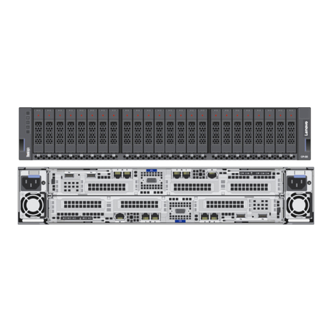
Lenovo ThinkSystem DM3000x Operating manual

ThinkSystem DM3000x and DM5000x
Hardware Installation and Maintenance Guide
Machine Types: 7Y 1, 7Y 2, 7Y57, 7D7W, 7D7U, 7D7V

Note
Before using this information and the product it supports, be sure to read and understand the safety
information and the safety instructions, which are available at:
http://thinksystem.lenovofiles.com/help/topic/safety_documentation/pdf_files.html
In addition, be sure that you are familiar with the terms and conditions of the Lenovo warranty for your
system, which can be found at:
http://datacentersupport.lenovo.com/warrantylookup
Seventh Edition (April 2023)
© Copyright enovo 2019, 2023.
LIMITED AND RESTRICTED RIGHTS NOTICE: If data or software is delivered pursuant to a General Services
Administration (GSA) contract, use, reproduction, or disclosure is subject to restrictions set forth in Contract No. GS-35F-
05925.

Contents
Contents . . . . . . . . . . . . . . . . . i
Safety . . . . . . . . . . . . . . . . . . iii
Chapter 1. Introduction . . . . . . . . . 1
Specifications . . . . . . . . . . . . . . . . 1
Management software . . . . . . . . . . . . . 3
Tech Tips . . . . . . . . . . . . . . . . . . 3
Security advisories . . . . . . . . . . . . . . 3
Chapter 2. System components. . . . . 5
Front view . . . . . . . . . . . . . . . . . . 5
Rear view . . . . . . . . . . . . . . . . . . 6
Rear view LEDs . . . . . . . . . . . . . . . . 7
Chapter 3. Rail kit installation
instructions . . . . . . . . . . . . . . 11
DM/DE Series 2U2 , 3U, U rail kit installation
instructions . . . . . . . . . . . . . . . . 11
DM/DE Series 2U12 rail kit installation
instructions . . . . . . . . . . . . . . . . 12
Chapter 4. System installation and
setup . . . . . . . . . . . . . . . . . . 17
Installation and setup high-level workflow . . . . 17
Preparing for installation . . . . . . . . . . . 17
Installing the hardware . . . . . . . . . . . . 18
Cabling a two-controller switchless cluster, unified
network configuration . . . . . . . . . . . . 19
Cabling a two-controller switchless cluster,
Ethernet network configuration . . . . . . . . . 20
Cabling a switched cluster, unified network
configuration . . . . . . . . . . . . . . . . 20
Cabling a switched cluster, Ethernet network
configuration . . . . . . . . . . . . . . . . 21
Cabling controllers to drive shelves . . . . . . . 22
Cabling storage on a two-controller switchless
cluster with no external storage . . . . . . . 22
Cabling storage on an HA pair with external
drive shelves . . . . . . . . . . . . . . 22
Completing system setup and configuration. . . . 23
Chapter 5. Hardware replacement
procedures . . . . . . . . . . . . . . . 27
Hot-swapping an internal disk drive . . . . . . . 27
Replacing the caching module . . . . . . . . . 28
Workflow diagram . . . . . . . . . . . . 28
Shutting down the degraded controller . . . . 29
Opening the system . . . . . . . . . . . 30
Replacing a caching module . . . . . . . . 32
Reinstalling the controller module . . . . . . 33
Running system-level diagnostics . . . . . . 3
Completing the replacement process . . . . 36
Replacing the NVMEM battery . . . . . . . . . 36
Workflow diagram . . . . . . . . . . . . 36
Shutting down the degraded controller . . . . 37
Opening the system . . . . . . . . . . . 38
Replacing the NVMEM battery . . . . . . . 0
Reinstalling the controller module . . . . . . 1
Running system-level diagnostics . . . . . . 2
Completing the replacement process . . . . 3
Swapping out a power supply . . . . . . . . .
Workflow diagram . . . . . . . . . . . . 5
Completing the replacement process . . . . 5
Replacing the controller module . . . . . . . . 5
Workflow diagram . . . . . . . . . . . . 6
Shutting down the degraded controller . . . . 7
Replacing the controller module hardware . . 8
Restoring and verifying the system
configuration . . . . . . . . . . . . . . 56
Completing system restoration . . . . . . . 60
Completing the replacement process . . . . 6
Important information after replacing the
controller module . . . . . . . . . . . . 6
Replacing a DIMM. . . . . . . . . . . . . . 6
Workflow diagram . . . . . . . . . . . . 6
Shutting down the degraded controller . . . . 65
Opening the system . . . . . . . . . . . 66
Replacing the DIMMs. . . . . . . . . . . 68
Reinstalling the controller module . . . . . . 70
Running system-level diagnostics . . . . . . 71
Completing the replacement process . . . . 73
Replacing the boot media . . . . . . . . . . . 73
Workflow diagram . . . . . . . . . . . . 73
Opening the system . . . . . . . . . . . 7
Replacing the boot media . . . . . . . . . 76
Transferring the boot image to the boot
media . . . . . . . . . . . . . . . . . 77
Completing the replacement process . . . . 79
Replacing the real-time clock battery . . . . . . 79
Workflow diagram . . . . . . . . . . . . 80
Shutting down the degraded controller . . . . 80
Opening the system . . . . . . . . . . . 81
Replacing the RTC battery . . . . . . . . . 83
Reinstalling the controller . . . . . . . . . 8
© Copyright Lenovo 2019, 2023 i

Completing the replacement process . . . . 85
Replacing the chassis . . . . . . . . . . . . 85
Workflow diagram . . . . . . . . . . . . 85
Shutting down the controller . . . . . . . . 86
Swapping out a power supply . . . . . . . 87
Removing the controller module . . . . . . 88
Moving drives to the new chassis . . . . . . 89
Replacing a chassis from within the
equipment rack or system cabinet. . . . . . 90
Installing the controller . . . . . . . . . . 90
Verifying and setting the HA state of the
chassis . . . . . . . . . . . . . . . . 91
Running system-level diagnostics . . . . . . 92
Completing the replacement process . . . . 95
Important information after replacing the
chassis . . . . . . . . . . . . . . . . 95
Chapter 6. System level
diagnostics. . . . . . . . . . . . . . . 97
Introduction to system-level diagnostics . . . . . 97
Requirements for running system-level
diagnostics. . . . . . . . . . . . . . . 97
How to use online command-line help . . . . 98
Running system installation diagnostics . . . . . 99
Running system panic diagnostics . . . . . . . 102
Running slow system response diagnostics . . . . 10
Running hardware installation diagnostics . . . . 108
Running device failure diagnostics . . . . . . . 111
Appendix A. Getting help and
technical assistance . . . . . . . . . . 115
Before you call . . . . . . . . . . . . . . . 115
Collecting service data . . . . . . . . . . . . 116
Contacting Support . . . . . . . . . . . . . 116
Appendix B. Notice of Privacy
Practices . . . . . . . . . . . . . . . . 117
Appendix C. Notices. . . . . . . . . . 119
Trademarks . . . . . . . . . . . . . . . . 120
Important notes . . . . . . . . . . . . . . . 120
Particulate contamination . . . . . . . . . . . 120
Telecommunication regulatory statement. . . . . 121
Electronic emission notices . . . . . . . . . . 121
Taiwan region BSMI RoHS declaration . . . . 122
Taiwan Region import and export contact
information . . . . . . . . . . . . . . . . 122
Index . . . . . . . . . . . . . . . . . . 123
ii ThinkSystem DM3000x and DM5000x Hardware Installation and Maintenance Guide

Safety
Before installing this product, read the Safety Information.
Antes de instalar este produto, leia as Informações de Segurança.
在安装本产品之前,请仔细阅读 Safety Information (安全信息)。
Læs sikkerhedsforskrifterne, før du installerer dette produkt.
Lees voordat u dit product installeert eerst de veiligheidsvoorschriften.
Ennen kuin asennat tämän tuotteen, lue turvaohjeet kohdasta Safety Information.
Avant d'installer ce produit, lisez les consignes de sécurité.
Vor der Installation dieses Produkts die Sicherheitshinweise lesen.
Prima di installare questo prodotto, leggere le Informazioni sulla Sicurezza.
Les sikkerhetsinformasjonen (Safety Information) før du installerer dette produktet.
Antes de instalar este produto, leia as Informações sobre Segurança.
© Copyright Lenovo 2019, 2023 iii

Antes de instalar este producto, lea la información de seguridad.
Läs säkerhetsinformationen innan du installerar den här produkten.
iv ThinkSystem DM3000x and DM5000x Hardware Installation and Maintenance Guide

Chapter 1. Introduction
This chapter provides a brief introduction to your system. This chapter contains information about product
specifications, management software, tech tips, and security advisories.
Specifications
The following information is a summary of the specifications of the system. Depending on the model, some
specifications might not apply.
Table 1. Specifications
Specification Description
Dimension • 2U
• For models with 12 drive bays in the front:
– Height: 86.9 mm (3. 2 inches)
– Width:
– With mounting flanges: 80 mm (18.9 inches)
– Without mounting flanges: 7 mm (17.6 inches)
– Depth:
– With cable management arm: 638 mm (25.12 inches)
– Without cable management arm: 508 mm (20 inches)
• For models with 2 drive bays in the front:
– Height: 85 mm (3.35 inches)
– Width:
– With mounting flanges: 80 mm (18.9 inches)
– Without mounting flanges: 7 mm (17.6 inches)
– Depth:
– With cable management arm: 613 mm (2 .13 inches)
– Without cable management arm: 83 mm (19.02 inches)
Clearance dimension • Front:
– For cooling: 153 mm (6.03 inches)
– For maintenance: 610 mm (2 .03 inches)
• Rear:
– For cooling: 153 mm (6.03 inches)
– For maintenance: 330 mm (13 inches)
Weight (with two controllers) • For models with 12 drive bays in the front: 28.9 kg (63.71 lb)
• For models with 2 drive bays in the front: 27.6 kg (60.85 lb)
Processor Two 6 bit 12-core 1.5 GHz processors
DIMM • Total capacity: 6 GB
• Four 16 GB DIMMs
• NVRAM/NVMEM used capacity: 8 GB
© Copyright Lenovo 2019, 2023 1

Table 1. Specifications (continued)
Specification Description
Power supplies Two hot-swap power supplies for redundancy support
Input/Output (I/O) features The system (with two controllers) has the following I/O ports:
• Four 12 Gb MiniSAS HD ports
• Four 10 Gb SFP+ Ethernet ports
• Eight 10 Gb/16 Gb UTA2 SFP+ ports or eight RJ 5 10 GbE host ports
• Two RJ 5 management ports
• Two host USB Type-A connectors
• Two RJ 5 console ports
• Two Micro-B USB console ports
Power input • Input voltage low range:
– Minimum: 100 V ac
– Maximum: 120 V ac
• Input voltage high range:
– Minimum: 200 V ac
– Maximum: 2 0 V ac
Environment The system is supported in the following environment:
• Air temperature:
– Operating: 5– 5°C ( 1–113°F)
– Storage or shipping: - 0–70°C (- 0–158°F)
• Relative humidity:
– Operating: 8%–90%
– Storage or shipping: 10%–95%
• Maximum altitude:
– Operating: 30 8 m (10000 ft)
– Storage: 12 192 m ( 0000 ft)
– Shipping: 12 192 m (39 989.8 ft)
2ThinkSystem DM3000x and DM5000x Hardware Installation and Maintenance Guide

Management software
ONTAP is available for managing your system. For detailed information about how to use ONTAP, go to:
http://thinksystem.lenovofiles.com/help/topic/ontap_software/overview.html
Tech Tips
Lenovo continually updates the support website with the latest tips and techniques that you can use to solve
issues that you might have with your system. These Tech Tips (also called retain tips or service bulletins)
provide procedures to work around issues related to the operation of your system.
To find the Tech Tips available for your system:
1. Go to http://datacentersupport.lenovo.com and navigate to the support page for your system.
2. Click How-tos & Solutions.
Expand Symptom to choose a category for the type is problem that you are having.
Security advisories
Lenovo is committed to developing products and services that adhere to the highest security standards in
order to protect our customers and their data. When potential vulnerabilities are reported, it is the
responsibility of the Lenovo Product Security Incident Response Team (PSIRT) to investigate and provide
information to our customers so they may put mitigation plans in place as we work toward providing
solutions.
The list of current advisories is available at the following site:
https://datacentersupport.lenovo.com/product_security/home
Chapter 1.Introduction 3

4ThinkSystem DM3000x and DM5000x Hardware Installation and Maintenance Guide

Chapter 2. System components
Use the information in this section to learn about each of the components associated with your system.
Front view
Front view with bezel
Figure 1. Front view with bezel
Table 2. Components on the front bezel
Components Status Description
1 Chassis power LED Solid green One or two of the power supply is delivering power to the system.
Off No power supply is delivering power to the system.
2 Chassis attention LED
(front)
Solid amber The system stops working or there is an error on the system.
Off The system is operating normally.
3 Chassis location LED
(front)
Solid blue or
blinking blue
The chassis location LED is manually activated to help locating the
chassis.
Off The chassis location LED is not activated.
4 Shelf ID digital display Number displayed Display the shelf ID.
© Copyright Lenovo 2019, 2023 5

Front view without bezel
Figure 2. Front view of models with 12 drive ba s
Figure 3. Front view of models with 24 drive ba s
Table 3. Components on the front of the s stem (without bezel)
1 Chassis power LED 2 Chassis attention LED (front) 3 Chassis location LED (front)
4 Shelf ID digital display 5 Shelf ID change button 6 Hot-swap drive bays (12/2 )
7 Drive activity LED 8 Drive status LED
Rear view
The rear of the system provides access to several connectors and components, including the power supplies
and various connectors.
6ThinkSystem DM3000x and DM5000x Hardware Installation and Maintenance Guide

Rear view – type 1
Figure 4. Rear view – t pe 1
Table 4. Components on the rear of the s stem
1 MiniSAS HD ports ( ) 2 SFP+ Ethernet ports ( )
3 UTA2 SFP+ ports (8) 4 Micro-B USB console ports (2)
5 RJ 5 console ports (2) 6 Host USB Type-A connectors (2)
7 RJ 5 management ports (2) 8 Power supply buttons (2)
9 Power supplies (2)
Rear view – type 2
Figure 5. Rear view – t pe 2
Table 5. Components on the rear of the s stem
1 MiniSAS HD ports ( ) 2 SFP+ Ethernet ports ( )
3 RJ 5 10 GbE host ports (8) 4 Micro-B USB console ports (2)
5 RJ 5 console ports (2) 6 Host USB Type-A connectors (2)
7 RJ 5 management ports (2) 8 Power supply buttons (2)
9 Power supplies (2)
Rear view EDs
The rear of the system provides system LEDs.
Chapter 2.System components 7

Figure 6. Rear view LEDs – t pe 1
Table 6. LEDs on the rear of the s stem
1 MiniSAS HD port link LED ( ) 2 MiniSAS HD port attention LED ( )
3 SFP+ Ethernet port link LED ( ) 4 SFP+ Ethernet port attention LED ( )
5 UTA2 SFP+ port link LED (8) 6 UTA2 SFP+ port attention LED (8)
7 Controller activity LED (2) 8 Controller attention LED (2)
9 Controller location LED (2) 10 NVRAM LED
11 RJ 5 management port link LED (2) 12 RJ 5 management port activity LED (2)
13 Power supply attention LED (2) 14 AC power good LED (2)
Figure 7. Rear view LEDs – t pe 2
Table 7. LEDs on the rear of the s stem
1 MiniSAS HD port link LED ( ) 2 MiniSAS HD port attention LED ( )
3 SFP+ Ethernet port link LED ( ) 4 SFP+ Ethernet port attention LED ( )
5 RJ 5 10 GbE host port link LED (8) 6 RJ 5 10 GbE host port activity LED (8)
7 Controller activity LED (2) 8 Controller attention LED (2)
9 Controller location LED (2) 10 NVRAM LED
8ThinkSystem DM3000x and DM5000x Hardware Installation and Maintenance Guide

Table 7. LEDs on the rear of the s stem (continued)
11 RJ 5 management port link LED (2) 12 RJ 5 management port activity LED (2)
13 Power supply attention LED (2) 14 AC power good LED (2)
1 2 MiniSAS HD port EDs
Each MiniSAS HD port has two status LEDs.
Status ED Color Status Description
1 MiniSAS HD port link LED Green On Link is established on at least one external
SAS lane.
None Off No link is established on any external SAS
lane
2 MiniSAS HD port
attention LED
Yellow On SAS link requires attention.
None Off SAS link operates normally.
3 4 SFP+ Ethernet port EDs
Each SFP+ Ethernet port has two status LEDs.
Status ED Color Status Description
3 SFP+ Ethernet port link
LED
Green On A connection is established on the port.
None Off No connection is established on the port.
4 SFP+ Ethernet port
attention LED
Amber On The port requires attention.
None Off The port operates normally.
5 6 Type 1 – UTA2 SFP+ port EDs
Each UTA2 SFP+ port has two status LEDs.
Status ED Color Status Description
5 UTA2 SFP+ port link LED Green On A connection is established on the port.
None Off No connection is established on the port.
6 UTA2 SFP+ port attention
LED
Amber On The port requires attention.
None Off The port operates normally.
5 6 Type 2 – RJ45 10 GbE host port EDs
Each RJ 5 10 GbE host port has two status LEDs.
Status ED Color Status Description
5 RJ 5 10 GbE host port
link LED
Green On A link is established between the port and
some upstream device.
None Off No link is established.
6 RJ 5 10 GbE host port
activity LED
Amber Blinking Traffic is flowing over the connection.
None Off No traffic is flowing over the connection.
Chapter 2.System components 9

7 Controller activity ED
Status Color Description
On Green The controller is active.
Off None The controller is off.
8 Controller attention ED
Status Color Description
On Yellow The controller requires attention.
Off None The controller operates normally.
9 Controller location ED
Status Color Description
On or blinking Blue The controller location LED is manually activated to help
locating the controller.
Off None The controller location LED is not activated.
10 NVRAM ED
Status Color Description
Blinking Green IO is being written to local flash memory.
On Green Data is in cache and has not been written to local disks.
Off None No data is in cache that needs to be written to local disks.
11 12 RJ45 management port EDs
Each RJ 5 management port has two status LEDs.
Status ED Color Status Description
11 RJ 5 management port
link LED Green On A link is established between the port and
some upstream device.
None Off No link is established.
12 RJ 5 management port
activity LED
Amber Blinking Traffic is flowing over the connection.
None Off No traffic is flowing over the connection.
13 Power supply attention ED
Status Color Description
On Amber No AC power is present or power supply is failed.
Off None AC power is present.
14 AC power good ED
Status Color Description
On Green AC power is present and good.
Off None AC power is not detected.
10 ThinkSystem DM3000x and DM5000x Hardware Installation and Maintenance Guide

Chapter 3. Rail kit installation instructions
This chapter includes information about rail kit installation instructions.
DM/DE Series 2U24, 3U, 4U rail kit installation instructions
The Rail can be either installed on a standard square-hole four-post rack or a standard round-hole four-post
rack by using the round-to-square hole adaptor brackets. Before you begin, verify that you have the correct
rail type by examining the PN label located on the rail (PN: SM17A38397).
Installing Rail to square-hole four-post rack
© Copyright Lenovo 2019, 2023 11

Installing Rail to round-hole four-post rack
DM/DE Series 2U12 rail kit installation instructions
Using this rail kit, a 2U 12-drive enclosure can be installed in a four-post rack.
Before you begin
The rail kit includes the following items:
• A pair of slide rails for four-post racks with alignment screws installed for the square-hole rack
• (Optional) rack alignment guide tool
• Flat-head M5 screws pre-installed in rails, qty 8
• Round-head M5 screws pre-installed in rails, qty 2
• Alignment screws
Verify that you have the correct rail type by examining the PN label located on the outer box for the following:
• Four-Post: SM17A38396
12 ThinkSystem DM3000x and DM5000x Hardware Installation and Maintenance Guide

The kit includes the following types of screws:
Type of hardware Description Quantity
Flat-head M5 screw; 1
mm long
You use six M5 screws for attaching the rails to
the rack, and two M5 screws for attaching the
brackets at the back of the enclosure to the
brackets at the back of the rails.
8
Round-head M5 screw;
12 mm long
You use these screws to attach the enclosure
to the rails.
2
Alignment screws for
racks with square holes
9. mm (head) X 7.5 mm
(length)
The 9. mm head screws align the rails in the
square-hole rack, 2 in each of corners.
Note: Alignment screws for square-hole racks
come pre-installed in the rails.
8
Alignment screws for
racks with round holes
7 mm (head) X 7.5 mm
(length)
8
About this Procedure
• You can install the enclosure in either a square-hole or round-hole rack.
• You must use only the screws that are provided in the kit.
Step 1. Determine where you want to install the enclosure in the rack.Use the rack alignment guide tool to
ensure that you install the enclosure at the same level on either post of the rack.
Note: When possible, install enclosures starting at the bottom of the rack and working up, so that
you can use the enclosures underneath as a guide for installing the next set of rails.
Step 2. Remove the M5 screws from each of the rail ends and the side brackets and saved. Make sure to
leave the 8 outer alignment screws (9. mm head for the square-hole rack) in the rail flanges for
proper alignment in the rack.
a. If you have a round-hole rack, remove the eight pre-installed square-hole rack alignment
screws and install the eight round-hole rack alignment screws.
Note: Ensure that you use the screws that are appropriate for your rack.
b. Place the rail inside the rack where you want to install the enclosure, and align the alignment
screws on the rail with the holes on the front post of the rack.
c. Extend the rail to the back post of the rack until the flanges on the rail touch the inside of the
rack.
d. Insert one flat-head M5 screw through the hole in the front of the rack, and two flat-head M5
screws through the holes at the back of the rack.
Chapter 3.Rail kit installation instructions 13

e. Repeat these steps for the other rail.
Step 3. Place the back of the enclosure (the end with the connectors) on the rails.
Attention: A fully loaded enclosure weighs approximately 65 lb (29 kg). Two persons are required
to safely move the enclosure.
Step . Carefully slide the enclosure all the way onto the rails.
Note: If applicable, you might need to remove the shelf end caps or the system bezel to secure the
enclosure to the rack post; if so, you need to replace the end caps or bezel when you are done.
Attention:
• You might need to adjust the rails to ensure that the enclosure slides all the way onto the rails.
• Two M5 screws are used to secure the enclosure to the back of the rails. You might need to
remove the M5 screws on the inner rail to ensure that the enclosure slides all the way back.
Attention: Do not place additional equipment on the rails after you finish installing the enclosure.
The rails are not designed to bear additional weight.
Step 5. Secure the enclosure to the front of the rack and rails by inserting two round-head M5 screws
through the mounting brackets (pre-installed on either side of the front of the enclosure), the holes
on the rack, and the holes on the front of rails.
14 ThinkSystem DM3000x and DM5000x Hardware Installation and Maintenance Guide
This manual suits for next models
7
Table of contents
Other Lenovo Network Storage Server manuals

Lenovo
Lenovo ThinkAgile CP Series Manual

Lenovo
Lenovo EMC PX4-300D User manual

Lenovo
Lenovo PX12-450R Owner's manual

Lenovo
Lenovo Storage N4610 Owner's manual

Lenovo
Lenovo ThinkSystem D4390 Operating manual

Lenovo
Lenovo ThinkAgile CP Use and care manual

Lenovo
Lenovo 415711U - THINKSTATION S20 TWR W3520 2.8G User manual
Popular Network Storage Server manuals by other brands

Hitachi
Hitachi Simple Modular Storage 100 user guide

Intel
Intel SS4200-E - Entry Storage System NAS Server user guide

American Megatrends
American Megatrends StorTrends 1312-J Specifications

Thecus
Thecus N16000 series user manual

Keyscan
Keyscan KS-NAS-120 A1 Quick installation guide

Rocstor
Rocstor Enteroc N1823 Hardware manual