S019
CAUTIO :
The power-control button on the device does not turn off the electrical current supplied to the device.
The device also might have more than one connection to dc power. To remove all electrical current
from the device, ensure that all connections to dc power are disconnected at the dc power input
terminals.
S029
DA GER
Electrical current from power, telephone, and communication cables is hazardous.
To avoid a shock hazard:
• Do not connect or disconnect any cables or perform installation, maintenance, or reconfiguration
of this product during an electrical storm.
• Connect all power cords to a properly wired and grounded power source.
• Connect to properly wired power sources any equipment that will be attached to this product.
• When possible, use one hand only to connect or disconnect signal cables.
• ever turn on any equipment when there is evidence of fire, water, or structural damage.
• Disconnect the attached ac power cords, dc power sources, network connections,
telecommunications systems, and serial cables before you open the device covers, unless you
are instructed otherwise in the installation and configuration procedures.
• Connect and disconnect cables as described in the following table when you install, move, or
open covers on this product or attached devices.
To Connect: To Disconnect:
1. Turn OFF all power sources and equipment that is to
be attached to this product.
2. Attach signal cables to the product.
3. Attach power cords to the product.
• For ac systems, use appliance inlets.
• For dc systems, ensure correct polarity of -48 dc
connections: RTN is + and -48 dc is -. Earth
ground should use a two-hole lug for safety.
4. Attach signal cables to other devices.
5. Connect power cords to their sources.
6. Turn ON all the power sources.
1. Turn OFF all power sources and equipment that is to
be attached to this product.
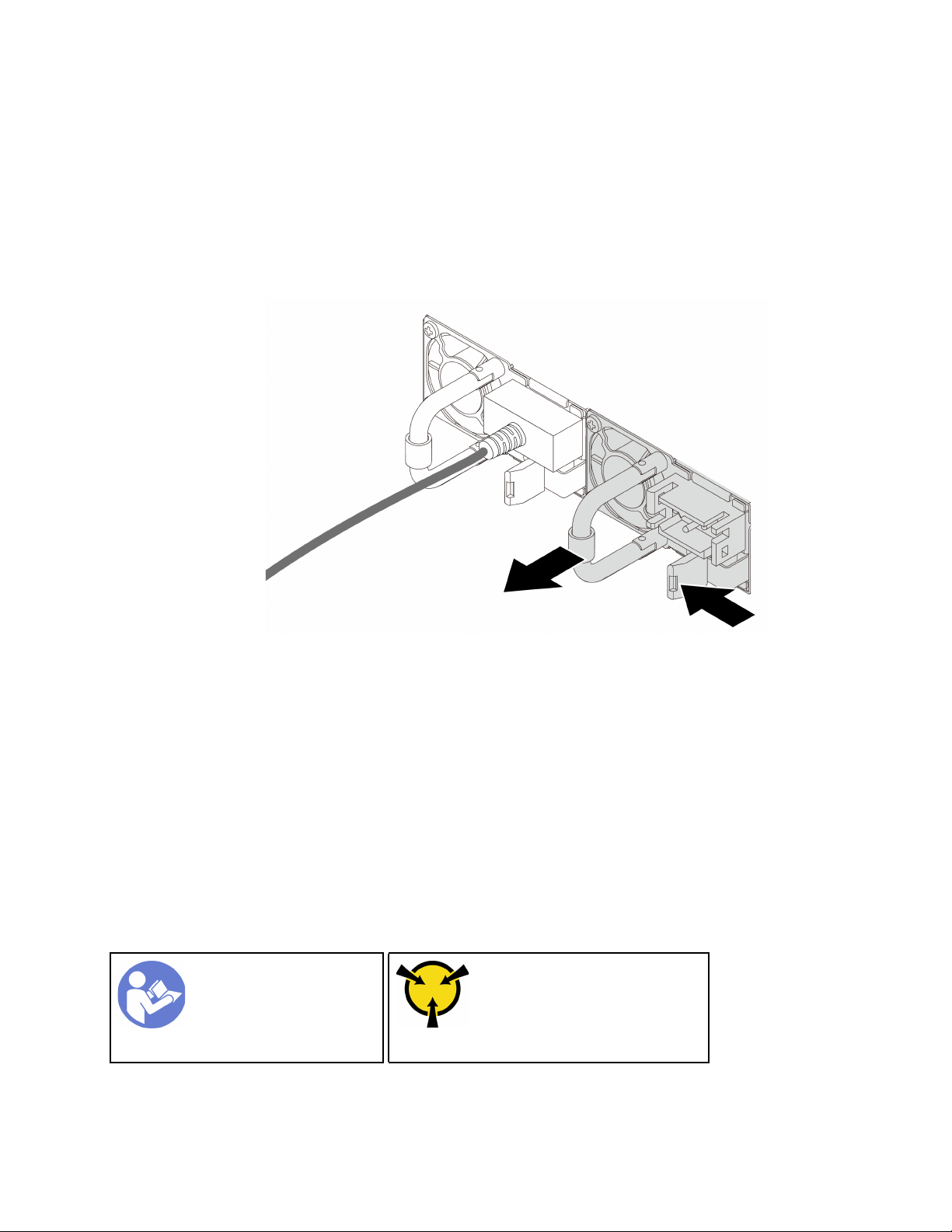
• For ac systems, remove all power cords from the
chassis power receptacles or interrupt power at
the ac power distribution unit.
• For dc systems, disconnect dc power sources at
the breaker panel or by turning off the power
source. Then, remove the dc cables.
2. Remove the signal cables from the connectors.
3. Remove all cables from the devices.
55