Wieland gesis KNX PS160 User manual
Doc. # BA000522 – 02/2013 (Rev. B) gesis KNX PS... 1 / 2
DE
Spannungsversorgung
gesis KNX PS160 83.020.1413.0
gesis KNX PS320 83.020.1414.0
gesis KNX PS640 83.020.1415.0
Produkt- und Funktionsbeschreibung
Die Spannungsversorgung gesis KNX PS erzeugt die für das
KNX-System erforderliche Versorgungsspannung. Die Ver-
bindung mit der Buslinie erfolgt durch die frontseitige Bus-
klemme.
Integrierte Drosseln verhindert den Kurzschluss der Da-
tentelegramme auf der Buslinie. Durch Betätigen des einge-
bauten Reset-Schalters werden die Busteilnehmer in den für
Busspannungswiederkehr parametrierten Betriebszustand
gesetzt. (Betätigung > 20 s).
Für jede Buslinie wird mindestens eine Spannungsver-
sorgung benötigt. Maximal sind zwei Spannungsversorgun-
gen in einer Buslinie zulässig.
Eine zweite Spannungsversorgung ist nur erforderlich, wenn
die Betriebsspannung an einem Teilnehmer unter 21V ab-
fällt.
Werden mehr als 30 Busteilnehmer z. B. in einem Vertei-
ler mit kurzen Leitungsdistanzen (z. B. 10 m) eingebaut, soll
die Spannungsversorgung gesis KNX PS in der Nähe dieser
Busteilnehmer angeordnet werden. Die Entfernung zwischen
der Spannungsversorgung gesis KNX PS und einem Busge-
rät darf max. 350 m betragen.
Die Spannungsversorgung gesis KNX PS ist auf Grund ei-
ner integrierten Spannungs- und Stromregelung kurz-
schlussfest. Kurze Netzunterbrechungen überbrückt das
Netzteil mit ca. 200 ms Pufferzeit.
Aus Gründen der Versorgungssicherheit wird empfohlen,
für den Netzanschluss der Spannungsversorgung gesis KNX
PS einen eigenen, separat abgesicherten Stromkreis zu ver-
wenden.
Bei allen Spannungsversorgungen kann die Ausgangs-
spannung unverdrosselt an einem zusätzlichen Klemmen-
paar abgegriffen werden. Diese Ausgangsspannung kann z.
B. zur Versorgung einer zusätzlichen Linie über eine separate
Drossel (optional erhältlich) genutzt werden.
Applikationsprogramme
Keine
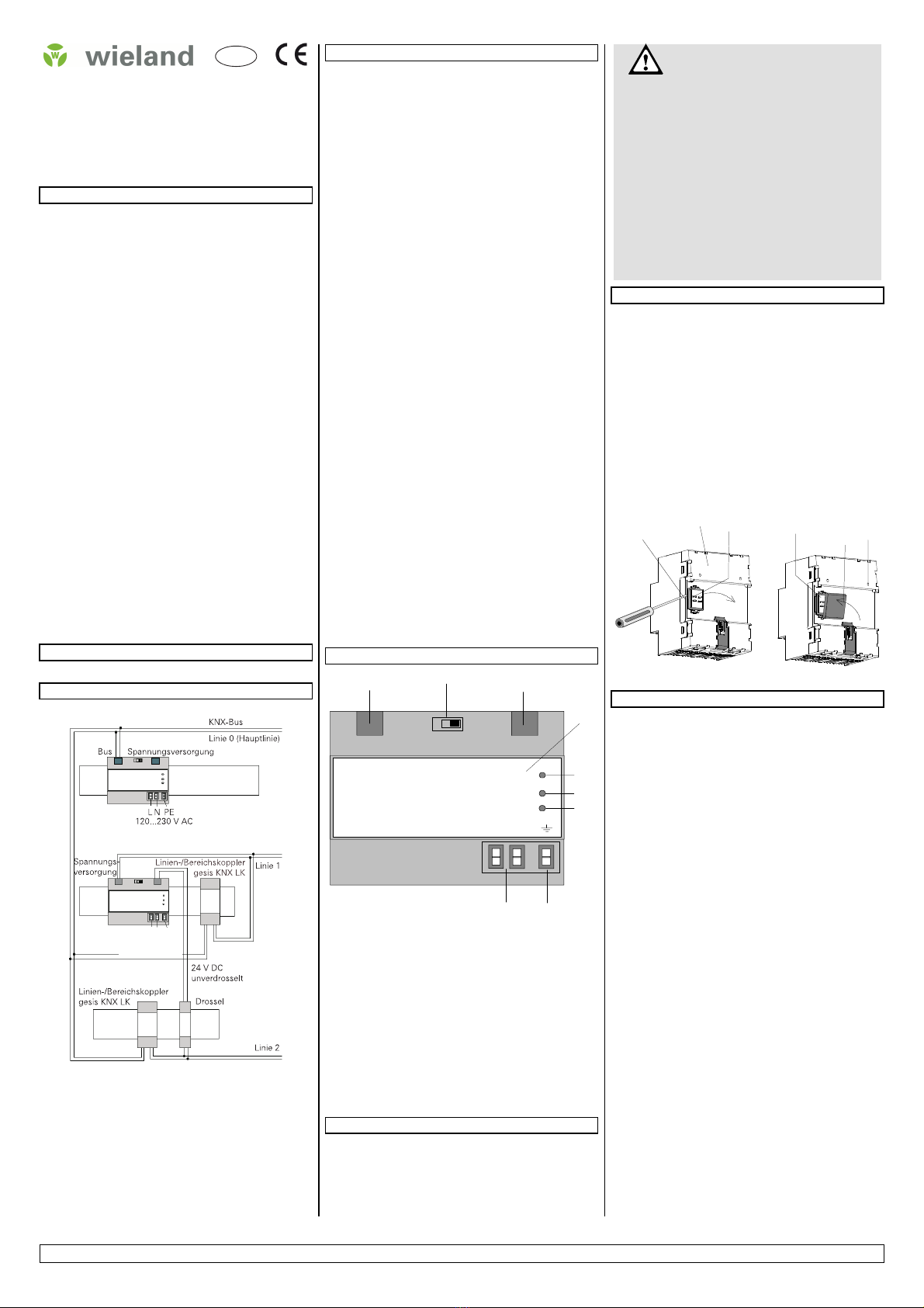
Anschlussbeispiel
Technische Daten
Eingangsspannung
•Bemessungsspannung AC 120...230 V, 50 ... 60 Hz
DC 220 V
•zulässiger Bereich AC 102 ... 253 V
Leistungsaufnahme
ca. 24 VA
Ausgangsspannung
•Bemessungsspannung DC 29 V
•Schutzkleinspannung (SELV)
•zulässiger Bereich DC 28 ... 30 V
Ausgangsstrom
•Bemessungsstrom 160 mA (gesis KNX PS160),
320 mA (gesis KNX PS320),
640 mA (gesis KNX PS640)
•Kurzschlussstrom:
begrenzt auf 1,0 A (gesis KNX PS160, PS320)
1,5 A (gesis KNX PS640)
Pufferzeit
bei Ausfall der Eingangsspannung ca. 200 ms
bei Bemessungsstrom
Anschlüsse
•Netzspannung, Steckklemmen schraubenlos:
Abisolierlänge 9...10 mm
Es sind folgende Leiterquerschnitte zulässig:
-
0,5 ... 2,5 mm² unvorbereitet
•Buslinie:
Druckkontakte auf Datenschiene,
Busklemme (schwarz-rot), schraubenlos
0,6 ... 0,8 mm ∅eindrähtig
Leiter ca. 5 mm abisolieren
•Ausgangsspannung unverdrosselt:
Kleinspannungsklemme (gelb-weiß), schraubenlos
0,6 ... 0,8 mm ∅eindrähtig
Leiter ca. 5 mm abisolieren
Mechanische Daten
•Abmessungen: Reiheneinbaugerät im N-Maß,
Breite 4 TE
•Gewicht: ca. 240 g
Elektrische Sicherheit
•Schutzart (nach EN 60529): IP 20
Umweltbedingungen
•Umgebungstemperatur im Betrieb: - 5...+45 °C
•Lagertemperatur: - 25...+70 °C
•rel. Feuchte (nicht kondensierend): 5 % bis 93 %
Lage- und Funktion der Anzeige- und Bedienelemente
LN
A1 A2 A3
A4
A5
A6
A7
A8 A9
+ -
+ -
Bild 1: Lage der Anzeigeelemente/Klemmen
A1 Kleinspannungsklemme (Busklemme rot-schwarz)
A2 Reset-Schalter
A3 Kleinspannungsklemme (unverdrosselte Spannung
gelb-weiß)
A4 Typenschild
A5 rote LED: Die Spannungsversorgung befindet sich in
der Resetstellung
A6 grüne LED: Die Spannungsversorgung gesis KNX PS
arbeitet in einem ordnungsgemäßen Betrieb
A7 rote LED: Die Teilnehmerlast ist zu hoch
oder die Buslinie ist kurzgeschlossen
A8 Schraubenlose Steckklemmen zum Anschluss der Ver-
sorgungsspannung (Netzklemmen)
A9 Erdungsklemme
Installationshinweise
Das Gerät kann für feste Installation in Innenräumen, für tro-
ckene Räume, zum Einbau in Starkstromverteiler oder Klein-
gehäusen auf Hutschienen EN 60715-TH35-7,5 verwendet
werden.
•
WARNUNG
•Das Gerät darf im Starkstromverteiler (230/400V) zusam-
men mit entsprechenden, VDE zugelassenen Geräten
eingebaut werden.
•Das Gerät darf nur von einer zugelassenen Elektrofach-
kraft installiert und in Betrieb genommen werden.
•Freie Hutschienenbereiche mit eingelegter Datenschiene
sind mit einer Abdeckung (optional erhältlich) zu verse-
hen.
•Beim Anschluss des Gerätes ist darauf zu achten, dass
das Gerät freigeschaltet werden kann.
•Die geltenden Sicherheits- und Unfallverhütungsvor-
schriften sind zu beachten.
•Das Gerät darf nicht geöffnet werden.
•Bei der Planung und Errichtung von elektrischen Anlagen
sind die einschlägigen Richtlinien, Vorschriften und Best-
immungen des jeweiligen Landes zu beachten.
Montage und Verdrahtung
Verbindung zum KNX - Bus
Der KNX – Bus wird über die Busklemme rot-schwarz am
Gerät kontaktiert. Es ist darauf zu achten, dass die beilie-
gende Isolierkappe zum Abdecken der Hutschienenkontakte
am Gerät angebracht ist, um ausreichende Isolation zur Hut-
schiene zu gewährleisten.
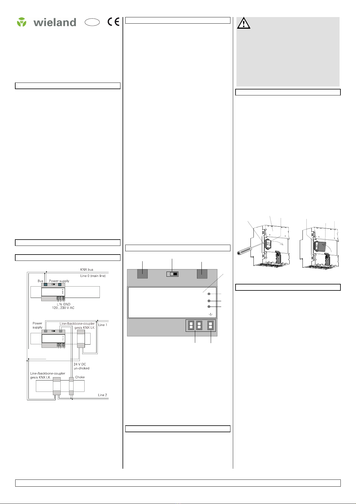
Abnehmen der Fixierung (Bild 2)
-
Die Fixierung (D3) umschließt das Kontaktsystem (D2) auf
der Hinterseite des Gerätes (D1).
-
Den Schraubendreher zwischen dem Reiheneinbaugerät
(D1) und der Fixierung (D3) einführen und die Fixierung
herausziehen.
Aufschnappen der Isolierkappe (Bild 2)
-
Die Isolierkappe (D4) auf das Kontaktsystem stecken und
durch Drücken aufschnappen.
D3
D1 D2 D2 D4 D1
Bild 2: Abdecken des Kontaktsystems
Allgemeine Hinweise
Defekte Geräte dürfen nicht geöffnet werden und sind zu-
rückzuschicken an
Wieland Electric GmbH
Qualitätssicherung
Brenner Straße 10–14
96052 Bamberg
Tel.: +49(951)9324-0
Fax: +49(951)9324-198
220 V DC
L N PE
120…230 V AC
220 V DC
Doc. # BA000522 – 02/2013 (Rev. B) gesis KNX PS... 2 / 2
EN
Power Supply Unit
gesis KNX PS160 83.020.1413.0
gesis KNX PS320 83.020.1414.0
gesis KNX PS640 83.020.1415.0
Product and Applications Description
The power supply unit gesis KNX PS provides the system
power necessary for the KNX bus system. The connection to
the bus line is established via the bus connection block lo-
cated on the front side.
The integrated choke prevents the data telegrams from
short-circuiting on the bus line. When the built-in reset
switch is operated (operation > 20s), the bus devices are re-
turned to their configured operating mode.
For each bus line, at least one power supply unit is need-
ed. Up to two power supply units may be attached to a sin-
gle bus line.
A second unit is not required unless the supply voltage at a
bus device is less than 21V.
When more than 30 bus devices are installed in short bus
cable distance (e.g. 10m), e.g. in distribution boards, the
power supply unit gesis KNX PS should be arranged near
these bus devices. The distance between power supply unit
gesis KNX PS and any of its bus devices must not exceed
350m.
The power supply unit gesis KNX PS has a voltage and
current regulation and is therefore short-circuit proof. Short
power failures can be bridged with a backup interval of ap-
proximately 200ms.
To ensure an uninterrupted power supply a separate cir-
cuit with safety separation should be used for the power
supply unit gesis KNX PS power supply line.
All power supply units can supply un-choked output volt-
age via an additional pair of terminals. This output voltage
can be used to power e.g. an additional line via a separate
choke (optionally available).
Application Programs
Requires no application programs
Example of Operation
Technical Specifications
Input voltage
•rated voltage: AC 120…230 V, 50...60Hz
DC 220 V
•permissible range: AC 102 ... 253 V
Power input
approx. 24 VA
Output voltage
•rated voltage: DC 29 V
•safety extra low voltage (SELV)
•permissible range: DC 28 ... 30 V
Output current
•rated current 160 mA (gesis KNX PS160),
320 mA (gesis KNX PS320),
640 mA (gesis KNX PS640)
•short-circuit current:
limited to 1,0 A (gesis KNX PS160, PS320)
1,5 A (gesis KNX PS640)
Backup interval
on input voltage failure: approx. 200 ms at rated current
Connections
•mains connection, screwless plug-in terminals:
strip insulation for 9 ... 10 mm
permissible conductor types/cross sections:
-
0,5 ... 2,5 mm² unprepared
•bus line:
pressure contacts on data rail,
screwless extra low voltage terminal (red–black)
∅0,6 ... 0,8 mm, solid conductor
strip wire approx. 5 mm
•output voltage (no choke):
screwless extra low voltage terminal (yellow-white)
∅0,6 ... 0,8 mm, solid conductor
strip wire approx. 5 mm
Physical specifications
•dimensions: DIN-rail mounted device,
width: 4 SU (1 SU = 18 mm)
•weight: approx. 240 g
Electrical safety
•protection (according to EN 60529): IP 20
Environmental specifications
•ambient temperature operating: - 5 ... + 45 °C
•storage temperature: - 25 ... + 70 °C
•relative humidity (non-condensing): 5 % to 93 %
Position and Function of Display and Operator Elements
LN
A1 A2 A3
A4
A5
A6
A7
A8 A9
+ -
+ -
Figure 1: Location of the display and operator elements
A1 extra low-voltage bus terminals (red-black)
A2 reset switch
A3 extra low-voltage terminals (un-choked voltage yellow-
white)
A4 type plate
A5 red LED for indicating that the power supply unit
gesis
KNX PS is in reset position
A6 green LED for indicating normal operation of the power
supply unit gesis KNX PS
A7 red LED for indicating a shorted-out bus line or a device
over-load
A8 screwless plug-in terminals for connecting the mains
(mains terminals)
A9 ground terminal
Installation Instructions
The device may be used for permanent interior installations
in dry locations within distribution boards or small casings
with DIN rail EN 60715-TH35-7.5.
WARNING
WARNINGWARNING
WARNING
•The device may be built into distribution boards
(230/400V) together only with appropriate VDE-devices.
•The device must be mounted and commissioned by an
authorised electrician.
•Free DIN rail areas with sticked-in data rails must be
covered with covers.
•A safety disconnection of the device must be possible.
•The prevailing safety rules must be heeded.
•The device must not be opened.
•For planning and construction of electric installations, the
relevant guidelines, regulations and standards of the re-
spective country are to be considered.
Mounting and Wiring
General description
The power supply unit can be installed to any DIN-rail EN
60715 TH35-7,5 in distribution boards.
The connection to the bus line is established via bus connec-
tion block.
Take care that the type plates of all devices on a DIN-rail can
be read in the same direction, guaranteeing the devices are
polarised correctly.
Connection to the bus
If the connection is established via bus connection block
(data rail not installed) the data rail connection system has
to be covered with the enclosed insulation hood after remov-
ing the guiding hood e.g. with a screw driver to guarantee a
sufficient insulation from the DIN rail.
Removing the guiding top (Figure 2)
-
The guiding top (D3) surrounds the contact system (D2)
on the back side of the device (D1).
-
Insert the screw driver between the DIN-rail device (D1)
and the guiding hood (D3) and remove the guiding hood.
Inserting the insulation top (Figure 2)
-
Put the insulation top (D4) onto the contact system and
click it into place by a slight pressure.
D3
D1 D2 D2 D4 D1
Figure 2: Covering the contact system with insulation top
General Notes
Faulty devices must not be opened and have to be returned
to the manufacturer:
Wieland Electric GmbH
QC/QA Dept.
Brenner Straße 10–14
96052 Bamberg
Tel.: +49(951)9324-0
Fax: +49(951)9324-198
220 V DC
L N GND
120…230 V AC
220 V DC
This manual suits for next models
2
Table of contents
Languages:
Other Wieland Power Supply manuals


Popular Power Supply manuals by other brands

Videx
Videx 520MR Installation instruction

Poppstar
Poppstar 1008821 Instructions for use

TDK-Lambda
TDK-Lambda LZS-A1000-3 Installation, operation and maintenance manual

TDK-Lambda
TDK-Lambda 500A instruction manual

Calira
Calira EVS 17/07-DS/IU operating instructions

Monacor
Monacor PS-12CCD instruction manual


