Lenz LZE500 User manual

Mobile DVR
Model:LZE500
User Manual
www.xmlenz.com
Xiamen Lenz Communication Co.,Ltd

Table of Contents
Warning...........................................................................................................................................................3
DECLARATION OF CONFORMITY ..........................................................................................................4
Chapter 1 Product Introduction...................................................................................................................6
1.1 About E500.........................................................................................................................................6
1.2 Features...............................................................................................................................................6
1.3 Size......................................................................................................................................................6
1.4 Front Panel..........................................................................................................................................7
1.5 Back Panel ..........................................................................................................................................8
1.6 Specifications......................................................................................................................................9
Chapter 2 Installation..................................................................................................................................10
2.1 Installation.........................................................................................................................................10
2.2Hard disk box installation..................................................................................................................10
2.3 Wiring diagram.................................................................................................................................14
2.4 Interface ............................................................................................................................................14
2.5 Definition of each PIN......................................................................................................................18

3/ 19
Warning
This equipment complies with CE radiation exposure limits set forth for anuncontrolled environment. This eq
uipment should be installed and operated withminimum distance 20cm between the radiator & your body.
Restrictions in the 5 GHz band
According to Article 10 (10) of Directive 2014/53/EU, the packaging shows that this radio equipment will be
subject to some restrictions when placed on the market in Belgium (BE), Bulgaria (BG), the Czech Republic
(CZ), Denmark (DK), Germany (DE), Estonia (EE), Ireland (IE), Greece (EL), Spain (ES), France (FR),
Croatia (HR), Italy (IT), Cyprus (CY), Latvia (LV), Lithuania (LT), Luxembourg (LU), Hungary (HU), Malta
(MT), Netherlands (NL), Austria (AT), Poland (PL), Portugal (PT), Romania (RO), Slovenia (SI), Slovakia
(SK), Finland (FI), Sweden (SE), the United Kingdom (UK), Turkey (TR), Norway (NO), Switzerland (CH),
Iceland (IS), and Liechtenstein (LI).
The WLAN function for this device is restricted to indoor use only when operating in the 5150 to 5350 MHz
frequency range.

4/ 19
DECLARATION OF CONFORMITY
Applier certifies that the following designated product
Product Name: Mobile DVR
Model No.: LZE500
Is in conformity with thestandard(s)
EN60950-1:2006+A11:2009+A1:2010+A12:2011+A2:2013
EN62311:2008
Draft ETSI EN301489-1 V2.2.1
Draft ETSI EN 301 489-17 V3.2.0
Draft ETSI EN301489-19 V2.1.0
Draft ETSI EN301489-52 V1.1.0
EN303 413 V1.1.1
EN301908-1 V11.1.1
EN301908-13 V11.1.2
EN300 328V2.1.1
EN301 893V2.1.1
EN300 440V2.1.1
Complies with the essential protection requirements of Directives on Radio Equipment Directive
2014/53/EU.
The designated product was subject to sample testing for which CCIC Southern Electronic Product Testing (Shenzhen)
Co., Ltd.
issued test report number:
SET2019-05455; SET2019-05183; SET2019-05184;SET2019-05226;
SET2019-05445;SET2019-05446;SET2019-05447;SET2019-05478
The declaration is the sole responsibility of the applier.
Xiamen LENZ Communication Co.,Ltd
20F, Block A04,NO.365 Chengyi Street, Software Park 3, Xiamen,China
Date: 2019-05-17 Signature & Company stamp: LV HEPING

5/ 19
The device is restricted to indoor use only when operating in the 5150 to 5350 MHz frequency range.
AT
BE
BG
HR
CY
CZ
DK
EE
FI
FR
DE
EL
HU
IE
IT
LV
LT
LU
MT
NL
PL
PT
RO
SK
SI
ES
SE
UK

6/ 19
Chapter 1 Product Introduction
1.1 About E500
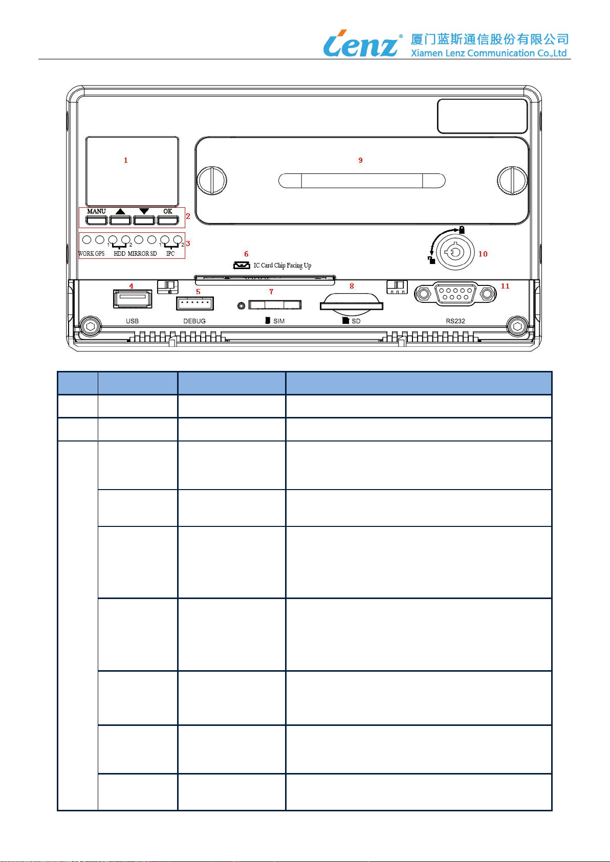
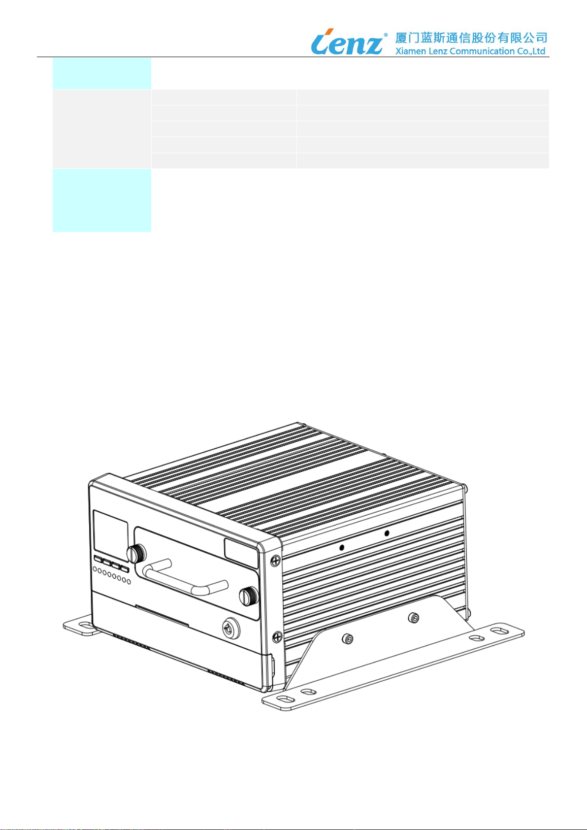
LZE500 Mobile DVR is a compact, full-featured recording system that uses SD card, hard disk (HDD) and solid
state disk (SSD) as the storage device. It provides H.264 high-quality and max 8 channels of 720P/1080P AHD
recording, and 8 channels of 720P/1080P high definition video surveillance and fleet management for police car,
ambulance, fire engine, public buses, tourist buses, etc.
The industrial-quality and fanless design of LZE500 enables the easy dissipation of heat. It could endure the
voltage surge in vehicle due to the advance power module design and strict quality testing, which is an ideal
solution for vehicle surveillance.
1.2 Features
1)8 channels 720P/1080P AHD +2 channels 1080P IPC video recording
2)Or 8 channels 1080P IPC video recording if connect with PON switch (for option)
3)Dual-stream technology adopted
4)AVL (automatic vehicle location) tracking by GPS and real-time dispatching
5)Support automatic bus stop announcement (for option)
6)Support to talk with control center through TTS speaker and microphone
7)Receive or send the message and display on driver monitor
8)OSD: overlay date, time, speed..on the footage
9)Alarms: over speed alarm, panic alarm, door open/close alarm, route deviation alarm, etc.
10) Patented vibration reduction technology
11) Configurable working parameters and firmware remotely or locally
12) The software is upgradable without replacing a new device.
1.3 Size
188mm(L)*188mm(W)*112mm(H)

7/ 19
1.4 Front Panel
No.
Item
Interface
Function
1
LCD
LCD
For Display
2
Button
Button
“MANU”,“▲”,“▼”,“OK”
3
WORK
Red LED
Indicates the device power-on and wireless network
connection status;
Fast flash: device registration network
Slow flash: The device is registered on the network.
GPS
Green LED
Indicating GPS/BDS positioning signal receiving status;
Fast flash: device is not positioned
Slow flash: The device is positioned
HDD1
Green LED
HDD1 indicator (located on the upper layer of the hard
disk box);
Light off: no storage medium recognized
Light on: recognize storage medium
Flashing: indicates that the storage medium is in the
read/write state.
HDD2
Green LED
HDD2 indicator (located on the down layer of the hard
disk box);
Light off: no storage medium recognized
Light on: recognize storage medium
Flashing: indicates that the storage medium is in the
read/write state.
MIRROR
Green LED
Black box light;
Light off: no device is recognized
Light on: recognize device
Flashing: indicates that the device is on work
SD
Green LED
Light off: no storage medium recognized
Light on: recognize storage medium
Flashing: indicates that the storage medium is in the
read/write state.
IPC1
Green LED
IPC1 indicator;
Light off: IPC is not connected
Light on: IPC Ethernet is connected

8/ 19
Flashing: IPC Ethernet has data transmission and
reception
IPC2
Green LED
IPC2 indicator;
Light off: IPC is not connected
Light on: IPC Ethernet is connected
Flashing: IPC Ethernet has data transmission and
reception
4
USB
USB Interface
Local upgrade
5
debug
Debugging
CPU serial port print information, Can be used for
upgrade
6
IC Card
Contact IC card
Driver identification card
7
SIM
With drawer type
card holder
Install SIM card for remote video and voice calls
8
SD
Self-elastic SD card
holder
For SD card auxiliary recording
9
Hard disk Box
Hard disk Box
Dual hard drive, pluggable
10
Hard disk lock
From open to closed, the hard disk box and the lower
cover can be locked at the same time.
11
RS232
DB9
External serial printer
1.5 Back Panel
No.
Item
Interface
Function
1
4G
SMA
4G Communication
2
3G
SMA
3G Communication
3
GPS
SMA
GPS/BD Positioning

9/ 19
4
POWER
M16 5P
Power Input
5
MIRROR
M12 5P
Black Box
6
PANEL
M16 10P
Driver console power support and communicating,
Speaker access,microphone access,CVBS video
output
7
IPC1-2
12 PIN interface
2 channels IPC access
8
AHD1-8
32 PIN interface
8-channel AHD camera access
9
RS232
6 PIN interface
Serious port
10
EXT.IO
30 PIN interface
RS232 interface, RS485 interface, CAN Bus
interface, High and low level detection, speed
detection etc
11
SPEAKER
4PIN interface
Audio out
1.6 Specifications
ITEM
TECHNICAL SPECIFICATION
SYSTEM
CPU Processor
ARM 9, 32 bit high performance CPU
Operation System
Linux
NETWORK
Wan
4G LTE
Wi-Fi
NC
GPS
TRACKING
Cold Start
<35 s
Hot Start
<2 s
Recapture
<2 s
Velocity Precision
≤1.0 m/s
Positioning Accuracy
≤5M
Tracking Sensitivity
Capture -144dBm, tracking -159dBm
VIDEO
Video Input
8 channels AHD+ 2 channels IPC
Image Resolution
CIF/D1/720P/1080P
IPC Solution (For Option)
8 channels IPC (powered by PON)
Image Resolution
CIF/D1/720P/1080P
Video Output
1 channel, CVBS
Video Format
ISO14496-10, PAL
Video Compression
H.264 main profile
Frame Rate
1-25 fps
AUDIO
Audio Input
10 channels
Audio Output
1 channel for speaker, 2 channels for PA
Audio Compression
8ch ADPCM for AHD, 2 ch G711 for IPC
STORAGE
HDD
Max 2*1TB 2.5’ SATA HDD/SSD
SD Card
Max 1*256G SD card
Black Box
Max 1* 64G for disaster backup
I/O
Sensors
7-CH DI, 2-CH DO
Com Port
3-CH RS232, 2-CH RS485
Can-Bus
1-CH CAN-bus, another 1CH for option

10 / 19
Network
1-CH RJ45 Ethernet converter interface
USB
1-CH USB, type A
POWER SUPPLY
Input Power
DC 9V ~ 36V, typical 12V/24V
Power Output-1
+5V@2A
Power Output-2
8CH +12V@500mA (analog cameras)
Power Output-3
2CH +12V@500mA (IP cameras)
Power Consumptions
<25W (not connect with accessories and HDD/SSD)
OTHERS
Operating Temperature
-20ºC~+70ºC
Size
188mm(L) *188mm(W)*112mm(H)
Weight
2.4kg
Certification
CE, RoHS, CCC
Chapter 2 Installation
2.1 Installation
The E500 is not allowed to be placed on the side. It should be laid flat. It is better to have some elevated positions to
prevent water from entering the car. The equipment is best installed on an outer protective box, which is sealed
around the protective box to prevent people from modifying the equipment, neat the wire harness and waterproof
when cleaning. The installation diagram is as follows:
2.2 Hard Disk Box Installation
Note:

11 / 19
Please use a 2.5-inch hard drive and purchase it from a regular store to ensure the quality of the hard drive.
After the hard disk is installed, you need to format it before you can record it, otherwise the system will
judge the hard disk error.

12 / 19

13 / 19

14 / 19
2.3 Wiring Diagram
2.4 Interface
2.4.1 4G Antenna
The interface standard of the antenna port is SMA male
External Antenna Antenna gain: 3.5 dBi

15 / 19
2.4.2 GPS Antenna
The GPS antenna adopts the standard SMA interface. The curved side of the GPS antenna is facing upwards, and
the flat side is facing downward. The fixed position must make the arc of the antenna face the sky, and there should
be no obstruction on the upper side. The metal-covered explosion-proof membrane will affect the reception of the
satellite signal, and the explosion-proof membrane at this position should be avoided or dug;
External Antenna Antenna gain: 3.5 dBi

16 / 19
2.4.4 Power
The following picture shows the 5-pin power cable, 5-pin connector to connect the device power interface, bare wire
part: the red wire is connected to the positive pole, the black wire is grounded, and the yellow wire is connected to the
ACC (required)
2.4.5 10-PIN Console
Can transfer speakers, microphone, Driver console;
2.4.6 30-PIN I/O Cable

17 / 19
2.4.7 SIM Card Installation
To purchase a SIM/UIM card from a telecom carrier, the card must be opened for data services; if voice calls are
required, voice services must be activated. Remove the SIM card slot and insert the SIM/UIM card as shown below.
Note that the side of the chip is facing down.
Step 1
Step 2
Step 3
The side of the chip is facing down.
Step 4

18 / 19
2.5 Definition of PINs
Pins on the device
Definition
Remark
1. Power +
2. Power +
3. ACC
4.GND
5.GND
Connect
power input,
ACC signal
input
1. DC 5V
2. USB-
3. USB+
4. GND
5. MIRROR access detection
1.DC 5V
2.RS232_RXD2
3.RS232_TXD2
4.MICP
5.MICN
6.SpeakerP
7.SpeakerN
8.GND
9.Video OUT
10.GND
Connect the
Driver
console,
speaker,
microphone,
1. IPC2_TX+
2. IPC2_RX+
3. GND
4. 12V IPC1
5. IPC1_RX-
6. IPC1_TX-
7. IPC2_TX-
8. IPC2_RX-
9. 12V IPC2
10. GND
11. IPC1_RX+
12. IPC1_TX+
1.12V camera8 power
2.Camera8
3.12V camera7 power
4.Camera7
5.12Vcamera 6 power
6.Camera 6
7.12Vcamera 5 power
8.Camera 5
17.GND
18.Audio 8
19.GND
20.Audio 7
21.GND
22.Audio 6
23.GND
24.Audio 5
8-channel
analog
camera

19 / 19
9.12Vcamera 4 power
10.Camera 4
11.12Vcamera 3 power
12.Camera 3
13.12Vcamera 2 power
14.Camera 2
15.12Vcamera 1 power
16.Camera 1
25.GND
26.Audio 4
27.GND
28.Audio 3
29.GND
30.Audio 2
31.GND
32.Audio 1
1.Reserved
2.Reserved
3.GND
4.232_TX
5.232_RX
6.GND
RS232
1. Debug_TX
2. GND
3. RS232-2-TX
4. A RS485+
5. B RS485+
6. GPS-TX
7. Door sensor
8. CANH1
9. CANH2
10. Brake
11. Right turn
12. Low beam
13. Panic button
14. Oil circuit control
15. GND
16. Debug_RX
17. GND
18. RS232-2-RX
19. A RS485-
20. B RS485-
21. GND
22. Horn
23. CANL1
24. CANL2
25. Left turn
26. High beam
27. Low level sensor
28. SPEED+
29. DC5V
30. GND
1.External speaker
2.Inner speaker
3.External speaker GND
4.Inner speaker GND

FCC Caution.
(1)§ 15.19 Labelling requirements.
This device complies with part 15 of the FCC Rules. Operation is subject to the following two
conditions: (1) This device may not cause harmful interference, and (2) this device must accept
any interference received, including interference that may cause undesired operation.
§ 15.21 Changes or modification warning
Any Changes or modifications not expressly approved by the party responsible for compliance
could void the user's authority to operate the equipment.
§ 15.105 Information to the user.
Note: This equipment has been tested and found to comply with the limits for a Class B digital
device, pursuant to part 15 of the FCC Rules. These limits are designed to provide reasonable
protection against harmful interference in a residential installation. This equipment generates uses
and can radiate radio frequency energy and, if not installed and used in accordance with the
instructions, may cause harmful interference to radio communications. However, there is no
guarantee that interference will not occur in a particular installation. If this equipment does cause
harmful interference to radio or television reception, which can be determined by turning the
equipment off and on, the user is encouraged to try to correct the interference by one or more of
the following measures:
-Reorient or relocate the receiving antenna.
-Increase the separation between the equipment and receiver.
-Connect the equipment into an outlet on a circuit different from that to which the receiver is
connected.
-Consult the dealer or an experienced radio/TV technician for help.
-This equipment complies with FCC radiation exposure limits set forth for an uncontrolled
environment.
--RF warning for Mobile device:
--This equipment complies with FCC radiation exposure limits set forth for an
uncontrolled environment.
-This equipment should be installed and operated with minimum distance 30cm between
the radiator &your body.
Table of contents
Popular DVR manuals by other brands

Mini Gadgets
Mini Gadgets MiniClocktravel user manual

Interlogix
Interlogix TruVision DVR 45HD user manual

March Networks
March Networks 8732 R, 8532 R installation guide

Night Owl
Night Owl WNVRC20 Series user manual

Vicon
Vicon Kollector Elite KE12 Installation

ERNITEC
ERNITEC MicroView MVINVR-08POEHP-E user manual