Lenz DIGITAL plus LV101 Owner's manual

Power Station LV101 1
DIGITAL plus
•52 Volt/Amp DCC Power Station
•Adjustable DCC Track Voltages
•Opto-isolation for Safety
•Clean DCC Track Power
•Designed to meet NMRA Control
Bus draft RP
Information
LV101
Art. No. 22101
March 1998

2Power Station LV101
The power station LV101
The DIGITAL plus LV101 Power Station is the “successor” of the
previously available LV100. New features include user selectable
DCC track voltages, a fault detection LED, and a new RJ-45
plug-in connector. This connector is provided now for new
devices currently under development. This allows you to
continue to use your LV101 in the future without modification.
The DIGITAL plus Power Station LV101 provides clean and safe
DCC power to the track. New circuitry has been developed to
reduce noise, which provides exceptionally clean power to
operate your DCC equipped trains. Safety features include:
•Short/overload detection that turns off the power to the track
whenever a short or overload condition is detected. This
protects both your trains and the LV101 electronics.
•Opto-isolation to safely isolate your control bus wiring from
your track wiring. This eliminates any possibility for hidden
ground loops through your power station.
•Fail Safe runaway protection is provided by requiring a 7 volt
signal on the DCC Control Bus (the C and D wires). This
prevents the LV101 from accidentally sending out power to
the track when the command station stops transmitting
packets.
A new feature in the LV101 is a fault detection LED located on
the front of the unit. When the power station is in use, the LED
on the front is lit. In case of an overload of the power station, the
LED will flash. In addition, the LED will also flash if no
information is being transmitted over the Control Bus
(connections Cand D), or one of the wires in not connected.
The LV101 Power Station was designed to meet all NMRA
Standards and RPs including the new the NMRA Control Bus
draft RP. This allows maximum interchangeability for use with
other conforming NRMA DCC systems. It has been submitted to
the NMRA for full conformance testing. It has passed all the
NMRA tests and the Conformance Warrant is pending.

Power Station LV101 3
DIGITAL plus
Connecting the Power Station
The LV101 Power Station takes its energy from a user supplied
AC transformer for model railroads. For maximum power, the
LV101 should be located near the track being powered, so that
the connection between the LV101 and the track is kept as short
as possible. Connect the transformer to terminals Uand V. For
maximum output power, the transformer voltage should be
selected to be close to the DCC track voltage. For HO scale
and smaller, a 16V AC or DC transformer is ideal. In order for
Figure 1Connecting LV101 to Command Station LZ100
the Power Station to give off its full 3A current, the transformer
also needs to be able to deliver a minimum of 4 amps. Use a
suitable, UL listed transformer designed for model trains. The
allowed maximum effective output voltage of the transformers
must not exceed 18V AC or DC.
The track is connected to terminals Jand K(see Figures 2 and 3).
Use only wire of sufficient gauge to connect to the tracks
(minimum 18 gauge) and either use parallel wires or twist the wires
to reduce radio interference.
Figure 2Connecting 2-rail track Figure 3Connecting 3-rail track

4Power Station LV101
The Power Station receives command information from the
Command Station via terminals Cand D. These terminals are
connected to the corresponding terminals on Command Station
LZ100 with a 2-wire cable. To reduce radio interface, these wires
should be twisted (see Figure 1).
When you connect terminal Ewith the corresponding terminal on
the Command Station LZ100, the Command Station will receive
feedback in case of a Power Station overload. This information
is then passed on to all handheld controllers. The display on
Handheld Controller LH100 will show "OFF" (AUS) followed by
“ON F1” (EIN F1). Once the short or overload is removed, the
system can be restarted by pressing the "F" key followed by the
"1" key and then "Enter".
If you have connected additional Power Stations to the
Command Station, they will turn off their layout sections as well.
You can turn the power supply for the layout back on via the
handheld controller (see LH100 section "Emergency
Stop/Emergency-Off"). A push button switch connecting
terminal Dwith the command station's terminal Ecan be located
at strategic places around the layout for emergency power
interruption to all power stations.
If you do not connect the LV101's terminal Ewith the Command
Station, then an overload will only turn off track power to the
layout section that the LV101 is connected to and the overload
will not affect the command station nor any other power station.
After a certain time (when the Power Station has cooled down
again) the Power Station automatically turns the power supply
back on. If the overload still is present, it will turn off again after
an additional short time.
The output current of the Power Station is limited by an
electronic fuse circuit to approximately 3A.
Six-Pin I/O - Port
The new six-pin phone type jack located on the rear of the
LV101 is provided for future use. Lenz GmbH is planning ahead
for future development. The wire connections for this I/O port are
shown in Figure 4.

Power Station LV101 5
DIGITAL plus
Figure 4: Wire connections for the LV101 6 pin -I/O port
Pin # Color Description
Pin 1 White "C" Control Bus Connection
Pin 2 Black Ground
Pin 3 Red - RS-485
Pin 4 Green + RS-485
Pin 5 Yellow +12 volts
Pin 6 Blue "D" Control Bus Connection
Installation considerations
There must not be a capacitor connected to the track for
interference control. A capacitor is only needed for conventional
operations to prevent radio interference. In DCC operation a
capacitor corrupts the data format and the error free data
transfer is disturbed.
It is normal for the Power Station to get warm during operation.
Ensure sufficient airflow around the Power Station to prevent the
internal safety circuit from activating during normal operations.
Never allow your layout to operate without supervision! If there is
an unnoticed short, the heat build-up could present a fire hazard!
Commom Rail Wiring
Normally both rails are gapped between power stations. This
provides complete isolation. However, in some scales there
exist locomotives that have pickups that are offset from each
other. For example many steam locomotives have power pickup
from one rail in the locomotive and the other rail in the tender.

6Power Station LV101
When such a locomotive bridges the gap between isolated
power stations, the locomotive will stall. The solution to this
problem is to provide a common wire between all the power
stations. All systems of command control need to have a such a
common provided, if offset pickup locomotives are to be
operated.
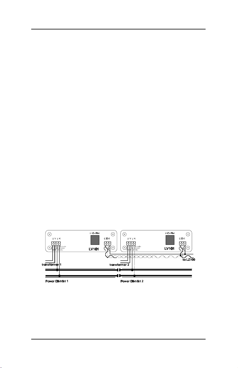
Lenz has chosen to leave the option of the location of the
common up to the individual operator. The LV101 is completely
opto-isolated. This allows you to use one of the rails (called
common rail) for your common. Common rail wiring is also
compatible with many existing signaling systems. While
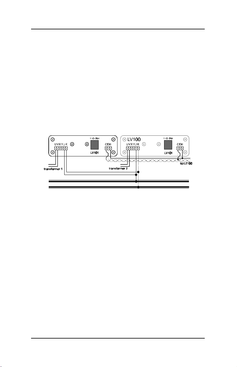
common rail is the preferred place for a common, you may
rather connect all the power station Uor Vwires together. This is
called common power supply wiring.
Caution: If you decide to install a common, it is important that
you only have a single common. Multiple commons (such as
common rail and common transformer) should be avoided.
Mixing Digital and Analog Operations
Conventional and digital track sections must be consistently
separated from each other by using isolating tracks or isolating
rail connectors between the digital and conventional (DC=) track
sections (double gapping).
At the gap dividing digital from analog operation, you must take
steps to prevent interference between the 2 systems when a
locomotive crosses the gap. One approach is to use a Digital
Circuit Breaker such as the LT130. If a locomotive bridges the
insulated gap, the module immediately interrupts the analog
power supply.
Warning:
Mixed digital/analog operations using both rails and catenary
(overhead wire) is not allowed. In this mode of operation, if the
locomotive is on the track in the wrong direction (for instance
after going through a loop), the built-in locomotive decoder could
be destroyed by excessive voltage! We suggest you operate
with current pickup from the rails (wheel pickups), since that
contact is more reliable (and thereby the transmission of the
digital signals to the locomotive decoder) than with catenary.

Power Station LV101 7
DIGITAL plus
Supplying power to a large model train layout
As in conventionally operated layouts, a sufficient power supply
is prerequisite for the safe function of a digital layout.
Locomotives, interior lights in rolling stock, turnouts, signals etc.
all get their power from the Power Station, along with their
commands. If the devices you have connected to an LV101
together require more than 3.0A, the safety circuit of the LV101
will activate. You will have an overload situation as described in
the section "Connecting the Power Station" above.
The current use of your layout is the sum of the following:
•locomotives in operation: depending on scale and load .2
Amps to 2 Amps. In N-scale, calculate ½ Amp, for H0 scale
estimate 1 Amp and for larger scales 2 Amps per
locomotive, and you will normally have some reserves.
•standing locomotives: without lights 1.5mA, with lights
approximately 50mA per light bulb
•rolling stock with lights: per light bulb approximately 50mA
If the output of a single LV101 is not enough to supply the
layout, then divide the layout into several power districts.
Additional LV101 units then will supply those areas with
approximately 3.0A each (one LV per power district)
In the supply area of one LV101, the current load of all
simultaneously operating locomotives must not exceed 3.0A
(including the current used for lighting in rolling stock).
Figure 4Connecting track voltage when using 2 LV101
The command signals reach additional LV101s through terminals
Cand Dof the first one. Each LV101 must be connected to its
own transformer. The number of transformer/Power Station
combinations needed for the layout thus depends on the power

8Power Station LV101
needs of your layout.
The power blocks of several LV101 must necessarily have the
same polarity. Terminal J of one and terminal J of the next LV101
must therefore be connected to the same rail. Otherwise there will
be a short when passing a dividing gap. (See Figure 1)
Setting the track voltage
As previously mentioned, LV101 provides the ability to adjust the
track voltage level. This adjustment is useful if you for instance
want a lower output voltage for an N scale layout. You can select
an area between 11.5V and 22V.
To adjust the track voltage, you must open the LV101.
On the circuit board you find a DIP-switch.
DCC Track
Voltage SW 1 SW 2 SW 3 SW 4
11.5 Volts On On On N/A
13 Volts Off On On N/A
14.5 Volts On Off On N/A
16 Volts Off Off On N/A
17.5 Volts On On Off N/A
19 Volts Off On Off N/A
20.5 Volts On Off Off N/A
22 Volts Off Off Off N/A
Depending on the position of each of the 4 switches on this DIP-
switch, you get a different output voltage at terminals J and K.
The switch positions necessary to get a particular voltage are
also printed on LV101’s circuit board.
In order to reach the desired output voltage, you must use a
transformer with an output voltage that is as high as the desired
track voltage. But do not overdo it: The transformer voltage
should be matched as closely as possible to the desired track
voltage. Too high of a transformer voltage just generates
unnecessary heat loss in the power station, and this will lead to
premature triggering of the overload fuse, before the maximum

Power Station LV101 9
DIGITAL plus
power output is reached.
Combining LV101s for larger output capacity
If your locomotives need a higher current than the 3.0A available
from the Power Station, you can connect two Power Stations in
parallel. Each Power Station is connected to its own transformer.
In this case you connect terminals Jand terminals Kon both
Power Stations with each other (Figure 5). You will then have
6.0A current available to power your trains.
Warning: If you wire your LV101s as in Figure 5the
shorting current is also 6.0A. This could in some cases lead
to damage to vehicle wheels or tracks, especially in the
smaller scales.
Figure 5Connecting track voltage for large scale railroads
Connecting a reverse loop
Lenz GmbH produces an automatic reversing module (LK100)
which can be used to easily wire complex automatic reversing
sections. While these units are invaluable in some cases they
are not absolutely needed for DCC operations. Following is an
example on how a very simple reversing section can be built.
Example:
Using isolated track contacts and a twin-coil relay, the polarity
inside a reverse loop is switched such that when crossing the
gaps, there is no short. For example; consider Figure 6when the
train travel is in clockwise direction (turnout is set to diverging
route).
When passing track contact b1, the polarity of the loop is set to
allow the train to cross the gap without a short. As the reverse
loop is traversed, track contact 2 will switch the polarity in the
loop, and the adjoining gap can be crossed safely. Since in

10 Power Station LV101
digital operations the direction of travel is dependent on the
locomotive and not track polarity, the locomotive will not change
its direction of travel when the polarity within the reverse loop is
changed.
a1
a2
b1
b2
~
~
= /
Power Supply
for Relays Twin-coil Relay
Isolated Track Contacts
Figure 6: Wiring of Reverse Loops
Traveling the reverse loop counter-clockwise is done in a similar
manner, now contacts a1 and a2 ensure that proper polarity is set.
Notes:
The distance between track contacts a2 and b2 must be longer
than the longest train that travels the reverse loop.
If the reverse loop is only traversed in one direction, then either
contacts a1 and a2 or contacts b1 and b2 are not needed.
The track contacts used in this example can actually be auxiliary
contacts set by the switch machine for the switch.
If you wish to traverse the reverse loop with a locomotive without
a decoder (analog locomotive), proceed as follows:
•drive the entire train into the reverse loop (the train must be
between contacts a2 and b2)
•stop the train and change direction with your handheld (LH100).
•now manually change the polarity in the reverse loop (for
example by using push buttons connected in parallel with
track contacts a2 and b2)
•continue driving the train through the reverse loop.
You must use this sequence with analog locomotives (non-

Power Station LV101 11
DIGITAL plus
decoder equipped), since their direction of travel is dependent on
track polarity.
Connecting the LV101 to Other DCC Systems
The LV101 has been designed to be used with a broad range of
NMRA DCC systems. Following are diagrams to assist you in
connecting the LV101.
Troubleshooting the LV101
Problem Cause Solution
LV101 is not
operational LED does
not light up)
Power supply is interrupted,
power plug of transformer is not
in outlet or "U", "V" wires are not
connected to the transformer.
Ensure that the transformer
is on, has not overloaded or
shut off, check wiring from
transformer to LV101
There is a short circuit on the
layout. Remove the cause of the
short circuit.
LED flashes There is a power overload. Divide the layout into several
supply sections and power
these with additional power
stations/transformers.
The connection between LV101
and command station LZ100 is
broken , or there is a short circuit
(terminals C and D)
Check and correct these
connections.
The command station is not
transmitting packets. Exit programming mode or
press Ffollowed by 1
LV101 is operational
(LED lights), but
The connection from Power
Station to track is broken
(terminals J and K).
Test and correct
connections.
locomotives do not run
The command station off Press Ffollowed by 1

12 Power Station LV101
Warranty
Lenz GmbH does everything it can do to ensure that its products are free from
defects and will operate for the life of your model railroad equipment. From time to
time even the best engineered products fail either due to a faulty part or from
accidental mistakes in installation. To protect your investment in Digital Plus
products. Lenz GmbH offers a very aggressive 10 year Limited Warranty.
This warranty is not valid if the user has altered, intentionally misused the Digital
Plus product, or removed the product's protection, for example the heat shrink from
decoders and other devices. In this case a service charge will be applied for all
repairs or replacements. Should the user desire to alter a Digital Plus Product, they
should contact Lenz GmbH for prior authorization.
Year One: A full repair or replacement will be provided to the original purchaser
for any item that that has failed due to manufacturer defects or failures caused by
accidental user installation problems. Should the item no longer be produced and
the item is not repairable, a similar item will be substituted at the manufacturers
discretion. The user must pay for shipping to an authorized Lenz GmbH warranty
center.
Year 2 and 3: A full replacement for any item will be provided that has failed due
to manufacturer defects. If the failure was caused by accidental user installation or
use, a minimal service charge may be imposed. Should the item no longer be
produced and the item is not repairable, a similar item will be substituted at the
manufacturers discretion. The user must pay shipping to and from the authorized
Lenz GmbH warranty center during this portion of the warranty period.
Year 4-10: A minimal service charge will be placed on each item that has failed
due to manufacturer defects and/or accidental user installation problems. Should
the item no longer be produced and the item is not repairable, a similar item will be
substituted at the manufacturers discretion. The user must pay shipping to and
from the authorized Lenz GmbH warranty center during this portion of the warranty
period.
Please contact your dealer or authorized Lenz GmbH warranty center for specific
instructions and current service charges prior to returning any equipment for repair.
Hüttenbergstraße 29
35398 Gießen, Germany
Hotline: 06403 900 133
Fax: 06403 5332
http://www.lenz.com
Lenz Agency of North America
PO Box 143
Chelmsford, MA 01824
ph/fax: 978 250 1494
This equipment complies with Part 15 of FCC Rules. Operation is subject to the
following two conditions: (1) this device may not cause harmful interference, and
(2) this device must accept any interference received, including interference that
may cause undesired operation.
© 1998 Lenz GmbH, All Rights Reserved
This manual suits for next models
1
Table of contents