1
CMVLC401A
Contents
1 Safety Information .....................................................................................................................................................2
1.1 General ........................................................................................................................................................................ 2
1.2 Application ................................................................................................................................................................... 2
1.3 Installation .................................................................................................................................................................... 2
1.4 Electrical Connection .................................................................................................................................................... 2
1.5 Operation ..................................................................................................................................................................... 3
2 Introduction ...............................................................................................................................................................4
2.1 Module Specifications .................................................................................................................................................. 4
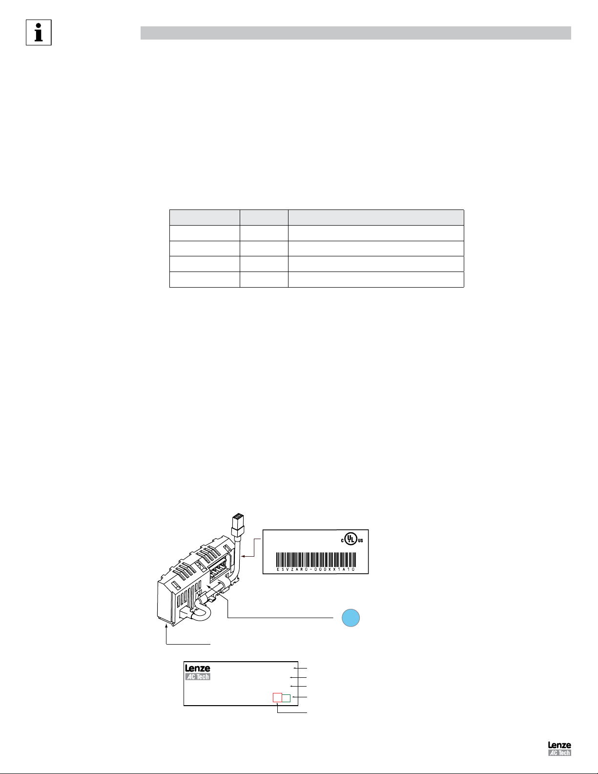
2.2 Module Identification Label ........................................................................................................................................... 4
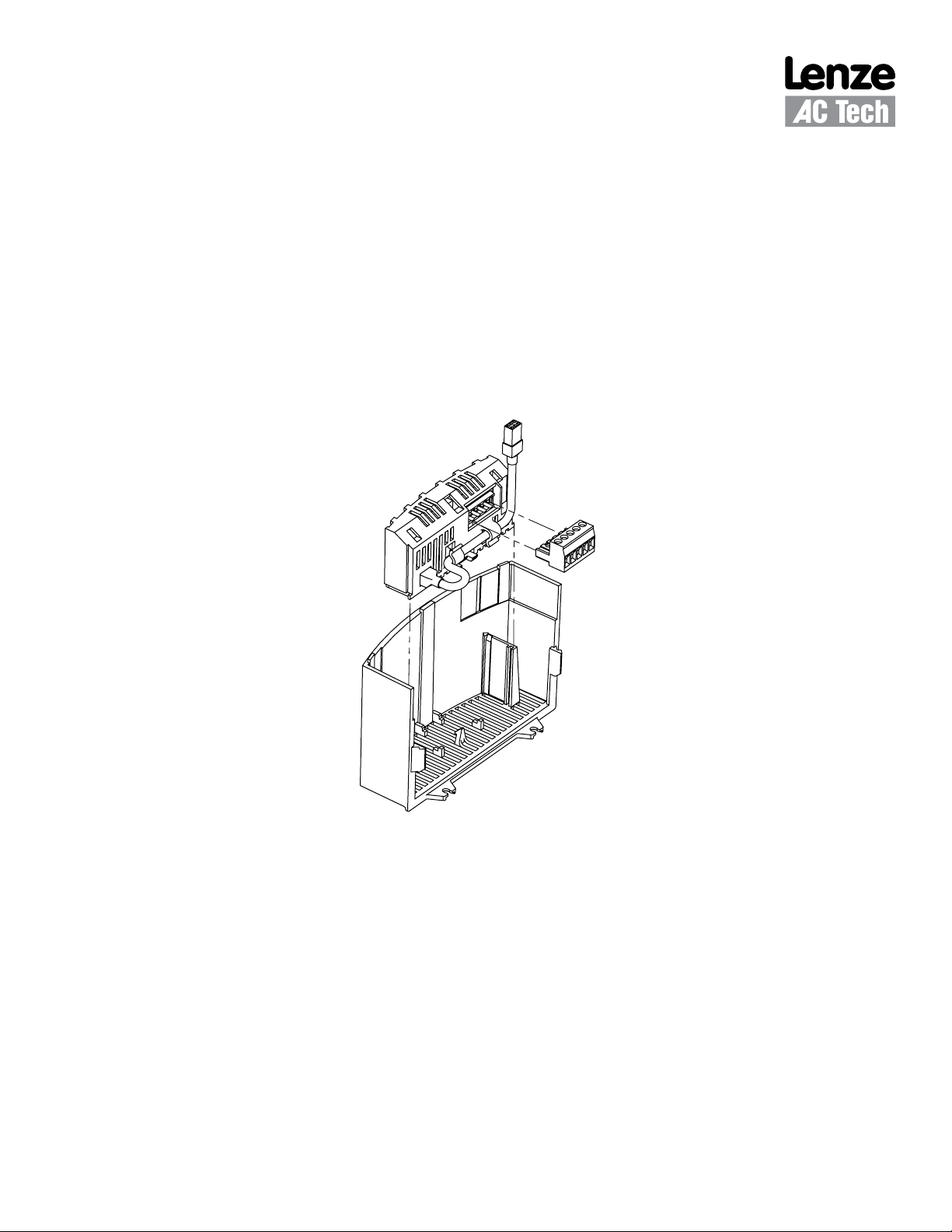
3 Installation .................................................................................................................................................................5
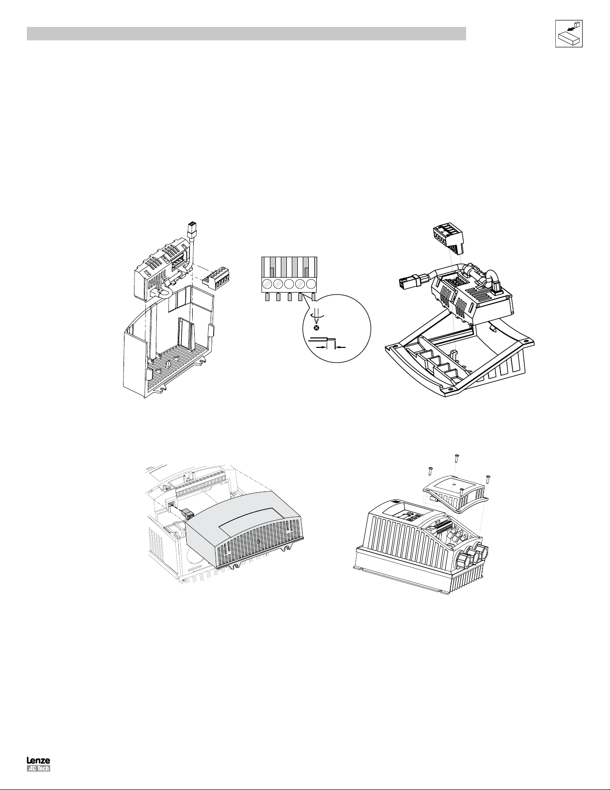
3.1 Mechanical Installation ................................................................................................................................................. 5
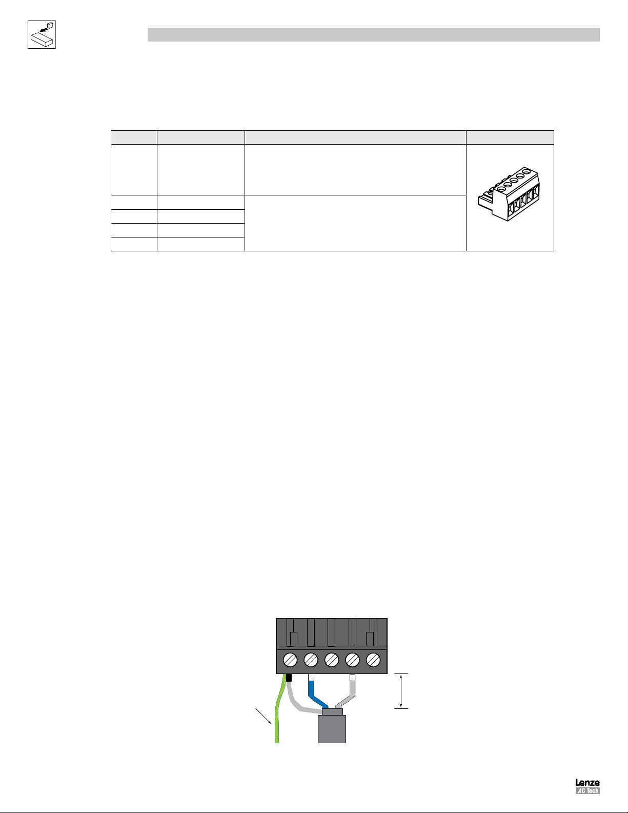
3.2 RS-485 Terminal Block................................................................................................................................................. 6
3.3 Electrical Installation..................................................................................................................................................... 6
3.3.1 Cable Types ................................................................................................................................................. 6
3.3.2 Network Limitations ..................................................................................................................................... 6
3.3.3 Connections and Shielding ........................................................................................................................... 6
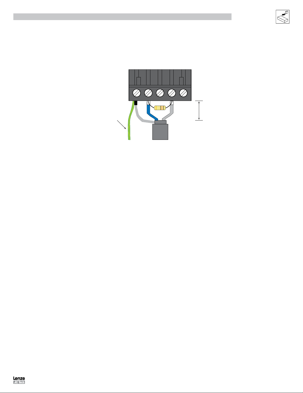
3.3.4 Network Termination ................................................................................................................................... 7
4 Parameters for use with RS-485/LECOM ....................................................................................................................8
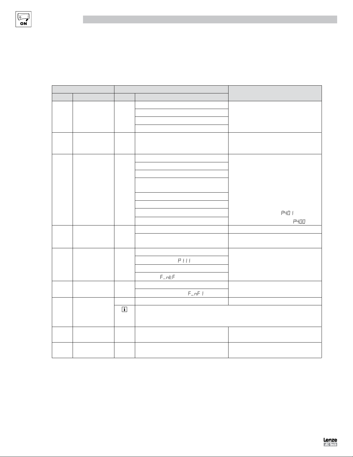
4.1 Drive Communication Parameters................................................................................................................................. 8
4.2 RS485 LECOM-Specific Parameters ............................................................................................................................. 9
5 LECOM Protocol Details ...........................................................................................................................................10
5.1 LECOM - A/B Protocol Description .............................................................................................................................. 10
5.2 Controller address (AD1, AD2) .................................................................................................................................... 10
5.3 Code Number (C1, C2) ................................................................................................................................................ 11
5.3.1 Standard Addressing.................................................................................................................................. 11
5.3.2 Addressing via Code Bank ......................................................................................................................... 11
5.3.3 Addressing via Input Selection ................................................................................................................... 12
5.3.4 Extended Addressing ................................................................................................................................. 12
5.4 Parameter Value (V1 to Vn) ......................................................................................................................................... 12
5.5 Block-Check Character (BCC) ..................................................................................................................................... 14
6 LECOM Message Details ..........................................................................................................................................15
6.1 Telegram Response .................................................................................................................................................... 15
6.2 Receive Telegram ....................................................................................................................................................... 15
6.3 Receive Telegram Response ....................................................................................................................................... 15
6.4 Send Telegram ........................................................................................................................................................... 16
6.4 Broadcast / Multicast .................................................................................................................................................. 17
7 Commissioning ........................................................................................................................................................18
7.1 Drive Monitoring ......................................................................................................................................................... 18
7.2 Drive Programming and Control .................................................................................................................................. 18
7.3 Network Watchdog Timer ........................................................................................................................................... 18
7.3.1 Watchdog Timer ........................................................................................................................................ 18
7.3.2 Watchdog Time-out Period (P425).............................................................................................................. 18
7.3.3 Watchdog Time-out Action (P426) .............................................................................................................. 18
8 Drive Registers ........................................................................................................................................................19
8.1 Configuration and Control Registers ............................................................................................................................ 19
8.1.1 C1050 (Network Controlled Digital Output) ................................................................................................. 22
8.1.2 C1055 (Network Controlled Analog Output) ................................................................................................ 22
8.1.3 C1099 (Parameter Version) ........................................................................................................................ 22
9 Programming Parameters ........................................................................................................................................23
9.1 Fault History (P500) .................................................................................................................................................... 23
9.2 Drive ID (P502) ........................................................................................................................................................... 24
9.3 Terminal and Protection Status (P530) ........................................................................................................................ 25
9.4 Keypad Status (P531) ................................................................................................................................................. 25
10 Troubleshooting and Fault Elimination ......................................................................................................................26
10.1 Faults ......................................................................................................................................................................... 26
10.2 Troubleshooting.......................................................................................................................................................... 26