Lenze E82ZBU User manual

Schalter-Poti-Einheit E82ZBU
für 8200 motec
MA82ZBU 1.0
Lenze GmbH & Co KG, Postfach 10 13 52, D-31763 Hameln
(
(+49) 5154 82-0, Fax Service: (+ 49) 5154 82-1112
Diese Anleitung
•beschreibt die Installation und die Handhabung der Schalter-Poti-Einheit.
•ist nur gültig
- für Schalter-Poti-Einheiten mit der Typenschildbezeichnung E82ZBU
- zusammen mit der Betriebsanleitung des zugehörigen Antriebsreglers.
Beschreibung
Die Schalter-Poti-Einheit E82ZBU ermöglicht
•die Vorgabe eines analogen Sollwertsignals für Lenze-Antriebsregler über die
Funktionsmodule Standard-I/O oder Application-I/O.
•die einfache Steuerung von Lenze-Antriebsreglern über die Digitaleingänge der
Funktionsmodule Standard-I/O oder Application-I/O (z. B. Drehrichtungsumkehr).
Einsatzbereich
Einsetzbar mit den Frequenzumrichter 8200 motec ab der Typenschildbezeichnung
E82MVxxx_4Bxxx 0x0x
Lieferumfang
1 Schalter-Poti-Einheit vorkonfektioniert mit 2,5 m Anschlußkabel
1 Befestigungsblech 60 mm x 60 mm
4 Schrauben M4 x 30 für die Befestigung der Schalter-Poti-Einheit
auf dem Befestigungsblech
2 Schrauben M4 x 20 mit Federblechen für die Befestigung am
Kühlkörper des motec
Allgemeine Daten und Einsatzbedingungen
Schutzart IP65
Abmessungen (B x H x T) ca.65mmx115mmx85mm
Montagemöglichkeiten am Kühlkörper des motec an einer Wand
EDK82ZBU
00415671
06/00
Show/Hide Bookmarks

Mechanische Installation
MA82ZBU 1.0
-2-
Sie können die Schalter-Poti-Einheit entweder am Kühlkörper des motec oder an einer
Wand befestigen.
Befestigung am Kühlkörper des motec
01. Befestigungsblech mit 2 Schrauben
M4 x 20 und 2 Federblechen
0
am
Kühlkörper befestigen.
2. Schalter-Poti-Einheit verdrahten
-mitStandard-I/O
&
3
- mit Application-I/O
&
4
3. Motec zusammenbauen
&
Montageanleitung motec
4. Schalter-Poti-Einheit mit 4
SchraubenM4x30
1
auf das
Befestigungsblech schrauben.
Befestigung an einer Wand 1. Befestigungsblech mit geeigneten
Schrauben an die Wand schrauben.
2. Schalter-Poti-Einheit mit 4
Schrauben M4 x 30 auf das
Befestigungsblech schrauben.
3. Schalter-Poti-Einheit verdrahten
-mitStandard-I/O
&
3
- mit Application-I/O
&
4
4. Motec zusammenbauen
&
Montageanleitung motec
Show/Hide Bookmarks

Verdrahtung mit Standard-I/O
MA82ZBU 1.0
-3-
Sollwertvorgabe über Potentiometer und Drehrichtungsumkehr (Links - Stop -
Rechts) über Schalter
Funktionsbeschreibung
•Der Ablauf nach dem Ausschalten (STOP)erfolgt an der Quickstop-Rampe
(C0105).
•Der Ablauf und Hochlauf nach dem Umschalten der Drehrichtung erfolgt an den
Rampen C0013 und C0012.
Das müssen Sie tun:
1. Schalter-Poti-Einheit an das Standard-I/O anschließen.
2. Hardware und Software des motec für Sollwertbereich 0 ... 5 V konfigurieren:
- Schalterstellung am Funktionsmodul anpassen.
- C0034 anpassen.
3. Zwei digitale Eingänge mit den Signalen CW/QSP und CCW/QSP konfigurieren
Beispiel für Klemmenkonfiguration C0007 = -16-
STANDARD S
762 8 9 720 28 E1 59E2 E3 E4 A139
12345
ON
89
X3
>100k
10k
72028
E1 E2 E3 E4 39 A1 59
762
GND1
+5V
1=CW 2=CCW
0
0
2
1
min max
Schalter-Poti-Einheit
ó
Drahtbrücken
Verdrahtung für Sollwertvorgabe über Potentiometer
Verdrahtung für Drehrichtungsumkehr über Schalter
CW Rechtslauf
CCW Linkslauf
Sollwertvorgabe Drehrichtungsumkehr
Klemmenbelegung X3/8: weißer Draht X3/20: gelber Draht
DC-Versorgung + 20 V
Drahtbrücke zu X3/28
“Reglersperre” (CINH)
X3/9: grüner Draht X3/E3: rosa Draht = Rechtslauf
(CW/QSP an X3/E3)
X3/7: brauner Draht X3/E4: grauer Draht = Linkslauf
(CCW/QSP an X3/E4)
Schalterstellung 1 2 3 4 5
S
c
h
a
l
t
e
r
s
t
e
l
l
u
n
g
OFF OFF ON OFF OFF
Parametrierung C0034 = -0- C0007 = -16-
Show/Hide Bookmarks

Verdrahtung Application-I/O
MA82ZBU 1.0
-4-
Sollwertvorgabe über Potentiometer und Drehrichtungsumkehr (Links - Stop -
Rechts) über Schalter
Funktionsbeschreibung
•Der Ablauf nach dem Ausschalten (STOP)erfolgt an der Quickstop-Rampe
(C0105).
•Der Ablauf und Hochlauf nach dem Umschalten der Drehrichtung erfolgt an den
Rampen C0013 und C0012.
Das müssen Sie tun:
1. Schalter-Poti-Einheit an das Application-I/O anschließen.
2. Hardware und Software des motec für Sollwertbereich 0 ... 5 V konfigurieren:
- Jumperstellung am Funktionsmodul anpassen.
- C0034 anpassen.
3. Zwei digitale Eingänge mit den Signalen CW/QSP und CCW/QSP konfigurieren
Beispiel für Klemmenkonfiguration C0007 = -16-
A2A1 7 7 A4 59 20 28 E1 E2 E3 E4 E5 E6
1U 1I 2U
10
9
8
7
2
1
4
3
6
5
2I 62 63 9
APPLICATION A
1
2
3
4
5
6
7
8
9
10
A
B
C
D
7 7
X3
>100k
10k
A4 59 20 28 E1 E2 E3 E4 E5 E6
A2A1
GND
+5V
1=CW 2=CCW
0
0
2
1
min max
2U 2I 62 63 9
1I
1U
>100k
GND
A2A1 7 7 A4 59 20 28 E1 E2 E3 E4 E5 E6
1U 1I 2U
10
9
8
7
2
1
4
3
6
5
2I 62 63 9
APPLICATION A
1
2
3
4
5
6
7
8
9
10
A
B
C
D
Schalter-Poti-Einheit
A2A1 7 7 A4 59 20 28 E1 E2 E3 E4 E5 E6
1U 1I 2U
10
9
8
7
2
1
4
3
6
5
2I 62 63 9
APPLICATION A
1
2
3
4
5
6
7
8
9
10
A
B
C
D
ó
Drahtbrücke
A2A1 7 7 A4 59 20 28 E1 E2 E3 E4 E5 E6
1U 1I 2U
10
9
8
7
2
1
4
3
6
5
2I 62 63 9
APPLICATION A
1
2
3
4
5
6
7
8
9
10
A
B
C
D
ì
Sollwertvorgabe ist möglichanX3/1UoderanX3/2U
A2A1 7 7 A4 59 20 28 E1 E2 E3 E4 E5 E6
1U 1I 2U
10
9
8
7
2
1
4
3
6
5
2I 62 63 9
APPLICATION A
1
2
3
4
5
6
7
8
9
10
A
B
C
D
Verdrahtung für Sollwertvorgabe über Potentiometer
A2A1 7 7 A4 59 20 28 E1 E2 E3 E4 E5 E6
1U 1I 2U
10
9
8
7
2
1
4
3
6
5
2I 62 63 9
APPLICATION A
1
2
3
4
5
6
7
8
9
10
A
B
C
D
Verdrahtung für Drehrichtungsumkehr über Schalter
A2A1 7 7 A4 59 20 28 E1 E2 E3 E4 E5 E6
1U 1I 2U
10
9
8
7
2
1
4
3
6
5
2I 62 63 9
APPLICATION A
1
2
3
4
5
6
7
8
9
10
A
B
C
D
CW Rechtslauf
A2A1 7 7 A4 59 20 28 E1 E2 E3 E4 E5 E6
1U 1I 2U
10
9
8
7
2
1
4
3
6
5
2I 62 63 9
APPLICATION A
1
2
3
4
5
6
7
8
9
10
A
B
C
D
CCW Linkslauf
Sollwertvorgabe Drehrichtungsumkehr
Klemmenbelegung X3/1U
oder
X3/2U
weißer Draht X3/20 gelber Draht
DC-Versorgung +20 V
Drahtbrücke zu X3/28
“Reglersperre” (CINH)
X3/9: grüner Draht X3/E3 rosa Draht = Rechtslauf
(CW/QSP an X3/E3)
X3/7 brauner Draht X3/E4 grauer Draht = Linkslauf
(CCW/QSP an X3/E4)
Jumperstellung Sollwert an X3/1U: Jumper A entfernen
J
u
m
p
e
r
s
t
e
l
l
u
n
g
Sollwert an X3/2U: Jumper B entfernen
Parametrierung Sollwert an X3/1U: C0034/1 = -0- C0007 = -16-
P
a
r
a
m
e
t
r
i
e
r
u
n
g
Sollwert an X3/2U: C0034/2 = -0-
C
0
0
0
7
1
6
Show/Hide Bookmarks

Andere Anwendungsbeispiele
MA82ZBU 1.0
-5-
Starten/Stoppen (CINH) mit Funktionsmodul Standard-I/O
Klemmenbelegung
X3/20 brauner Draht
DC-Versorgung +20 V
X3/28 weißer Draht
Start/Stopp
grüner Draht = unbenutzt
Geeignet isolieren!
Schalter-Poti-Einheit
ó
Drahtbrücke
Verdrahtung für Starten/Stoppen über
Schalter
CINH Reglersperre
/CINH Reglerfreigabe
Starten/Stoppen (CINH) mit Funktionsmodul Application-I/O
Klemmenbelegung
X3/20 brauner Draht
DC-Versorgung +20 V
X3/28 weißer Draht
Start/Stopp
grüner Draht = unbenutzt
Geeignet isolieren!
Schalter-Poti-Einheit
Verdrahtung für Starten/Stoppen über
Schalter
CINH Reglersperre
/CINH Reglerfreigabe
Sie können statt X3/28 auch einen Digitaleingang (X3/E1 ... X3/E6)
ansteuern und damit andere digitale Funktionen aktivieren, z. B.
Festfrequenz JOG1 an E1.
Show/Hide Bookmarks

Switch/potentiometer unit E82ZBU
for 8200 motec
MA82ZBU 1.0
Lenze GmbH & Co KG, Postfach 10 13 52, D-31763 Hameln
(
(+49) 5154 82-0, Fax Service: (+ 49) 5154 82-1112
These Instructions
•describe the installation and handling of the switch/potentiometer unit.
•are only valid
- for switch/potentiometer units with the nameplate data E82ZBU
- together withtheOperating Instructions of thecorresponding controller.
Description
The switch/potentiometer unit E82ZBU enables
•the selection of an analog setpoint signal for Lenze controllers through the function
modules Standard-I/O and Application-I/O.
•easy control of Lenze controllers through digital inputs of the function modules
Standard-I/O and Application-I/O (e. g. reversal of direction of rotation).
Range of application
To be used with 8200 motec frequency inverters as of nameplate label
E82MVxxx_4Bxxx 0x0x
Items supplied
1 switch/potentiometer unit with pre-cut 2.5 m connection cable
1 mounting sheet 60 mm x 60 mm
4 screws M4 x 30 for mounting the switch/potentiometer unit to the
mounting sheet
2 screws M4 x 20 with spring steel sheet for mounting to the
heatsink of the motec
General data and application conditions
Type of protection IP65
Dimensions (W x H x D) approx.65mmx115mmx85mm
Possible mounting positions Mounting to the heatsink of a
motec Mounting to a wall
EDK82ZBU
00415671
06/00
Show/Hide Bookmarks

Mechanical installation
MA82ZBU 1.0
-2-
The switch/potentiometer unit can be mounted to the heatsink of a motec or a wall.
Mounting to the heatsink of a motec
04. Mount the mounting plate with 2
screwsM4x20and2springsteel
sheets
0
to the heat sink.
5. Wire the switch/potentiometer unit
-tothestandard-I/O
&
3
- to the application-I/O
&
4
6. Assemble the motec
&
Mounting Instructions for motec
7. Mount the switch/potentiometer unit
with4screwsM4x30
1
to the
mounting plate.
Wall mounting 1. Mount the mounting plate to the wall
using appropriate screws
2. Mount the switch/potentiometer unit
with4screwsM4x30tothe
mounting plate.
3. Wire the switch/potentiometer unit
-totheStandard-I/O
&
3
- to the Application-I/O
&
4
4. Assemble the motec
&
Mounting Instructions for motec
Show/Hide Bookmarks

Wiring with Standard-I/O
MA82ZBU 1.0
-3-
Setpoint selection through potentiometer and reversal of direction of rotation (CCW
- stop - CW) through switch
Description of the functionality
•Deceleration after STOP along the quick stop ramp (C0105).
•Deceleration and acceleration after a reversal of the direction of rotation along
ramps C0013 and C0012.
For this, the following is required:
1. Connect the switch/potentiometer unit to the Standard-I/O.
2. Configure hardware and software of the motec for a setpoint range of 0 ... 5 V:
- Adapt the switch position at the function module.
- Adapt C0034.
3. Configure two digital inputs with the signals CW/QSP and CCW/QSP
Example for terminal configuration C0007 = -16-
STANDARD S
762 8 9 720 28 E1 59E2 E3 E4 A139
12345
ON
89
X3
>100k
10k
720 28 E1 E2 E3 E4 39 A1 59
7
62
GND1
+5V
1=CW 2=CCW
0
0
2
1
min max
Switch/potentiometer unit
ó
Wire bridges
Wiring for setpoint selection through potentiometer
Wiring for reversal of direction of rotation through
switch
CW CW rotation
CCW CCW rotation
Setpoint selection Change of direction of rotation
Terminal assignment X3/8: White wire X3/20: Yellow wire
DC supply +20 V
Wire bridge to X3/28
“Controller inhibit” (CINH)
X3/9: Green wire X3/E3: Pink wire = CW rotation
(CW/QSP on X3/E3)
X3/7: Brown wire X3/E4: Grey wire = CCW rotation
(CCW/QSP on X3/E4)
Switch position 1 2 3 4 5
S
w
i
t
c
h
p
o
s
i
t
i
o
n
OFF OFF ON OFF OFF
Parameter setting C0034 = -0- C0007 = -16-
Show/Hide Bookmarks

Wiring with Application-I/O
MA82ZBU 1.0
-4-
Setpoint selection through potentiometer and reversal of direction of rotation (CCW
- stop - CW) through switch
Description of the functionality
•Deceleration after STOP along the quick stop ramp (C0105).
•Deceleration and acceleration after a reversal of the direction of rotation along
ramps C0013 and C0012.
For this, the following is required:
1. Connect the switch/potentiometer unit to the Application-I/O.
2. Configure hardware and software of the motec for a setpoint range of 0 ... 5 V:
- Adapt the jumper position at the function module.
- Adapt C0034.
3. Configure two digital inputs with the signals CW/QSP and CCW/QSP
Example for terminal configuration C0007 = -16-
A2A1 7 7 A4 59 20 28 E1 E2 E3 E4 E5 E6
1U 1I 2U
10
9
8
7
2
1
4
3
6
5
2I 62 63 9
APPLICATION A
1
2
3
4
5
6
7
8
9
10
A
B
C
D
7 7
X3
>100k
10k
A4 59 20 28 E1 E2 E3 E4 E5 E6
A2A1
GND
+5V
1=CW 2=CCW
0
0
2
1
min max
2U 2I 62 63 9
1I
1U
>100k
GND
A2A1 7 7 A4 59 20 28 E1 E2 E3 E4 E5 E6
1U 1I 2U
10
9
8
7
2
1
4
3
6
5
2I 62 63 9
APPLICATION A
1
2
3
4
5
6
7
8
9
10
A
B
C
D
Switch/potentiometer unit
A2A1 7 7 A4 59 20 28 E1 E2 E3 E4 E5 E6
1U 1I 2U
10
9
8
7
2
1
4
3
6
5
2I 62 63 9
APPLICATION A
1
2
3
4
5
6
7
8
9
10
A
B
C
D
ó
Wire bridge
A2A1 7 7 A4 59 20 28 E1 E2 E3 E4 E5 E6
1U 1I 2U
10
9
8
7
2
1
4
3
6
5
2I 62 63 9
APPLICATION A
1
2
3
4
5
6
7
8
9
10
A
B
C
D
ì
Setpoint selection possible via X3/1Uor X3/2U
A2A1 7 7 A4 59 20 28 E1 E2 E3 E4 E5 E6
1U 1I 2U
10
9
8
7
2
1
4
3
6
5
2I 62 63 9
APPLICATION A
1
2
3
4
5
6
7
8
9
10
A
B
C
D
1Verdrahtung für Sollwertvorgabe über Potentiometer
A2A1 7 7 A4 59 20 28 E1 E2 E3 E4 E5 E6
1U 1I 2U
10
9
8
7
2
1
4
3
6
5
2I 62 63 9
APPLICATION A
1
2
3
4
5
6
7
8
9
10
A
B
C
D
Wiring for reversal of direction of rotation through
switch
A2A1 7 7 A4 59 20 28 E1 E2 E3 E4 E5 E6
1U 1I 2U
10
9
8
7
2
1
4
3
6
5
2I 62 63 9
APPLICATION A
1
2
3
4
5
6
7
8
9
10
A
B
C
D
CW CW rotation
A2A1 7 7 A4 59 20 28 E1 E2 E3 E4 E5 E6
1U 1I 2U
10
9
8
7
2
1
4
3
6
5
2I 62 63 9
APPLICATION A
1
2
3
4
5
6
7
8
9
10
A
B
C
D
CCW CCW rotation
Setpoint selection Change of direction of rotation
Terminal
assignment X3/1U
or
X3/2U
White wire X3/20 Yellow wire
DC supply +20 V
Wire bridge to X3/28
“Controller inhibit” (CINH)
X3/9: Green wire X3/E3 Pink wire = CW rotation
(CW/QSP on X3/E3)
X3/7 Brown wire X3/E4 Grey wire = CCW rotation
(CCW/QSP on X3/E4)
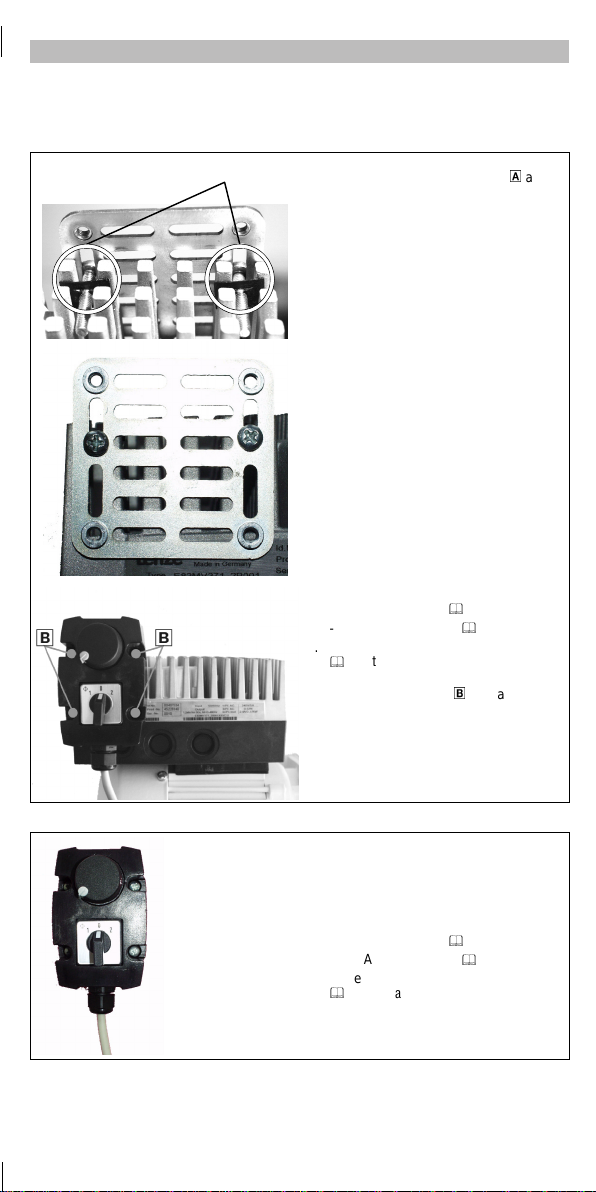
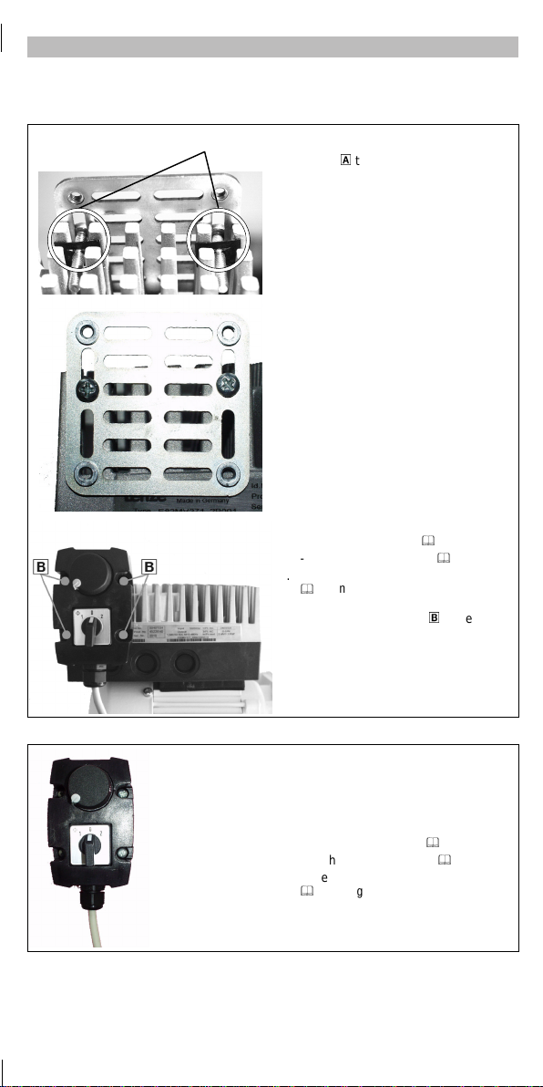
Jumper position Setpoint on X3/1U: Remove jumper A
J
u
m
p
e
r
p
o
s
i
t
i
o
n
Setpoint on X3/2U: Remove jumper B
Parameter setting Setpoint on X3/1U: C0034/1 = -0- C0007 = -16-
P
a
r
a
m
e
t
e
r
s
e
t
t
i
n
g
Setpoint on X3/2U: C0034/2 = -0-
C
0
0
0
7
1
6
Show/Hide Bookmarks

Other application examples
MA82ZBU 1.0
-5-
Starting/stopping (CINH) with the function module Standard-I/O
Terminal assignment
X3/20 Brown wire
DC supply +20 V
X3/28 White wire
Start/stop
Green wire = not used
Appropriate insulation!
Switch/potentiometer unit
ó
Wire bridge
Wiring for start/stop through switch
CINH Controller inhibit
/CINH Controller enable
Starting/stopping (CINH) with the function module Application-I/O
Terminal assignment
X3/20 Brown wire
DC supply +20 V
X3/28 White wire
Start/stop
Green wire = not used
Appropriate insulation!
Switch/potentiometer unit
Wiring for start/stop through switch
CINH Controller inhibit
/CINH Controller enable
Instead of using X3/28also digital input (X3/E1 ... X3/E6)can be connected
and thus different digital functions, e.g. JOG1 on E1, can be activated.
Show/Hide Bookmarks

Unité potentiomètre-interrupteur type
E82ZBU
pour 8200 motec
MA82ZBU 1.0
Lenze GmbH & Co KG, Postfach 10 13 52, D-31763 Hameln
(
(+49) 5154 82-0, Fax Service: (+ 49) 5154 82-1112
Le présent fascicule
•décrit l’installation et lamanipulation del’unité potentiomètre-interrupteur ;
•n’est valable que
- pour les unités potentiomètre-interrupteur E82ZBU (voir plaque signalétique);
- conjointement avec les instructions de mise en service du variateur de vitesse
concerné.
Description
L’unité potentiomètre-interrupteur E82ZBU permet
•une entrée d’un signal de consigne analogique pour les variateurs de vitesse
Lenze via les modules de fonction E/S standard et E/S application ;
•une commande simplifiée des variateurs de vitesse Lenze via les entrées
numériques des modules de fonction E/S standard ou E/S application (exemple :
inversion du sens de rotation).
Domaine d’utilisation
Utilisation possiblesur les convertisseurs de fréquence8200 motec à partir de laversion
suivante (voir plaque signalétique ): E82MVxxx_4Bxxx 0x0x
Equipement livré
1 unité potentiomètre-interrupteur précâblée avec câble de
raccordement 2,5 m
1tôledefixation60mmx60mm
4 vis M4 x 30 pour la fixation de l’unité potentiomètre-interrupteur
surlatôledefixation
2 vis M4 x 20 avec tôle-ressort pour la fixation sur le radiateur du
motec
Caractéristiques générales et conditions ambiantes
Protection IP65
Encombrements (L x H x P) Env. 65 mm x 115 mm x 85 mm
Montages possibles Sur le radiateur du motec Au mur
EDK82ZBU
00415671
06/00
Show/Hide Bookmarks

Installation mécanique
MA82ZBU 1.0
-2-
L’unité potentiomètre-interrupteur peut être monté soit sur le radiateur du motec soit au
mur.
Fixation sur le radiateur du motec
04. Fixerlatôledefixationavec2vis
M4 x 20 et 2 tôles-ressorts
0
sur le
radiateur.
5. Câbler l’unité
potentiomètre-interrupteur
- avec E/S standard
&
3
- avec E/S application
&
4
6. Assembler le motec.
&
Instructions de montage motec
7. Visser l’unité
potentiomètre-interrupteur sur la tôle
defixation
1
àl’aidedes4vis
M4 x 30.
Fixation au mur 1. Visserlatôledefixationaumurà
l’aide devis appropriées.
2. Visser l’unité
potentiomètre-interrupteur sur la tôle
defixationàl’aidede4visM4x30.
3. Câbler l’unité
potentiomètre-interrupteur
- avec E/S standard
&
3
- avec E/S application
&
4
4. Assembler le motec.
&
Instructions de montage motec
Show/Hide Bookmarks

Câblage avec E/S standard
MA82ZBU 1.0
-3-
Entrée de la consigne via potentiomètre et inversion du sens de rotation
(antihoraire - stop - horaire) via interrupteur
Principe de fonctionnement
•Après la coupure (STOP), la décélération s’effectue selon la rampe d’arrêt rapide
(C0105).
•Après inversion du sens de rotation, la décélération et l’accélération s’effectuent
selon les rampes C0013 et C0012.
Ce qu’il faut faire :
1. Raccorder l’unitépotentiomètre-interrupteur sur le module de fonction E/S
standard.
2. Configurer le matériel et le logiciel du motec pour une plage de consigne 0 ... 5 V :
- Adapter la position de l’interrupteur sur le module de fonction.
- Régler C0034.
3. Configurer deux entrées numériques avec les signaux CW/QSP (H/AR) et
CCW/QSP (AH/AR).
Exemple : Configuration des bornes C0007 = -16-
STANDARD S
762 8 9 720 28 E1 59E2 E3 E4 A139
12345
ON
89
X3
>100k
10k
72028
E1 E2 E3 E4 39 A1 59
762
GND1
+5V
1=CW 2=CCW
0
0
2
1
min max
Unité potentiomètre-interrupteur
ó
Fils de liaison
Câblagepourl’entréedelaconsigneviapotentiomètre
Câblage pour l’inversion du sens de rotation via
interrupteur
CW Sens horaire
CCW Sens antihoraire
Entrée de la consigne Inversiondusensderotation
Affectation des
bornes X3/8 Fil blanc X3/20 Fil jaune
Alimentation CC +20 V
Fil de liaison vers X3/28
“Blocage variateur” (CINH)
X3/9 Fil vert X3/E3 Fil rose = Sens horaire
(CW/QSP (H/AR) sur X3/E3)
X3/7 Fil brun X3/E4 Fil gris = Sens antihoraire
(CCW/QSP (AH/AR) sur
X3/E4)
Position interrupteur 1 2 3 4 5
P
o
s
i
t
i
o
n
i
n
t
e
r
r
u
p
t
e
u
r
OFF OFF ON OFF OFF
Paramétrage C0034 = -0- C0007 = -16-
Show/Hide Bookmarks

Câblage avec E/S application
MA82ZBU 1.0
-4-
Entrée de la consigne via potentiomètre et inversion du sens de rotation
(antihoraire - stop - horaire) via interrupteur
Principe de fonctionnement
•Après la coupure (STOP), la décélération s’effectue selon la rampe d’arrêt rapide
(C0105).
•Après inversion du sens de rotation, la décélération et l’accélération s’effectuent
selon les rampes C0013 et C0012.
Ce qu’il faut faire :
1. Raccorder l’unité potentiomètre-interrupteurs au module E/S application.
2. Configurer le matériel et le logiciel du motec pour une plage de consigne 0 ... 5 V :
- Adapter la position du pont sur lemodulede fonction.
-Régler C0034.
3. Configurer deux entrées numériques avec les signaux CW/QSP (H/AR) et
CCW/QSP (AH/AR).
Exemple : Configuration des bornes C0007 = -16-
A2A1 7 7 A4 59 20 28 E1 E2 E3 E4 E5 E6
1U 1I 2U
10
9
8
7
2
1
4
3
6
5
2I 62 63 9
APPLICATION A
1
2
3
4
5
6
7
8
9
10
A
B
C
D
7 7
X3
>100k
10k
A4 59 20 28 E1 E2 E3 E4 E5 E6
A2A1
GND
+5V
1=CW 2=CCW
0
0
2
1
min max
2U 2I 62 63 9
1I
1U
>100k
GND
A2A1 7 7 A4 59 20 28 E1 E2 E3 E4 E5 E6
1U 1I 2U
10
9
8
7
2
1
4
3
6
5
2I 62 63 9
APPLICATION A
1
2
3
4
5
6
7
8
9
10
A
B
C
D
Unité potentiomètre-interrupteur
A2A1 7 7 A4 59 20 28 E1 E2 E3 E4 E5 E6
1U 1I 2U
10
9
8
7
2
1
4
3
6
5
2I 62 63 9
APPLICATION A
1
2
3
4
5
6
7
8
9
10
A
B
C
D
ó
Fils de liaison
A2A1 7 7 A4 59 20 28 E1 E2 E3 E4 E5 E6
1U 1I 2U
10
9
8
7
2
1
4
3
6
5
2I 62 63 9
APPLICATION A
1
2
3
4
5
6
7
8
9
10
A
B
C
D
ì
Entrée de la consigne possible sur X3/1U ou X3/2U
A2A1 7 7 A4 59 20 28 E1 E2 E3 E4 E5 E6
1U 1I 2U
10
9
8
7
2
1
4
3
6
5
2I 62 63 9
APPLICATION A
1
2
3
4
5
6
7
8
9
10
A
B
C
D
Câblage pour l’entrée de la consigne via potentiomètre
A2A1 7 7 A4 59 20 28 E1 E2 E3 E4 E5 E6
1U 1I 2U
10
9
8
7
2
1
4
3
6
5
2I 62 63 9
APPLICATION A
1
2
3
4
5
6
7
8
9
10
A
B
C
D
Câblage pour l’inversion du sens de rotation via
interrupteur
A2A1 7 7 A4 59 20 28 E1 E2 E3 E4 E5 E6
1U 1I 2U
10
9
8
7
2
1
4
3
6
5
2I 62 63 9
APPLICATION A
1
2
3
4
5
6
7
8
9
10
A
B
C
D
CW Sens horaire
A2A1 7 7 A4 59 20 28 E1 E2 E3 E4 E5 E6
1U 1I 2U
10
9
8
7
2
1
4
3
6
5
2I 62 63 9
APPLICATION A
1
2
3
4
5
6
7
8
9
10
A
B
C
D
CCW Sens antihoraire
Entrée de la consigne Inversiondusensderotation
Affectation des
bornes X3/1U
ou
X3/2U
Fil blanc X3/20 Fil jaune
Alimentation CC +20 V
Fil de liaison vers X3/28
“Blocage variateur” (CINH)
X3/9 Fil vert X3/E3 Fil rose = Sens horaire
(CW/QSP (H/AR) sur
X3/E3)
X3/7 Fil brun X3/E4 Fil gris = Sens antihoraire
(CCW/QSP (AH/AR) sur
X3/E4)
Position des ponts Consigne sur X3/1U : Enlever le pont A.
P
o
s
i
t
i
o
n
d
e
s
p
o
n
t
s
Consigne sur X3/2U : Enlever le pont B.
Paramétrage Consigne sur X3/1U : C0034/1 = -0- C0007 = -16-
P
a
r
a
m
é
t
r
a
g
e
Consigne sur X3/2U : C0034/2 = -0-
C
0
0
0
7
1
6
Show/Hide Bookmarks

Autres exemples d’application
MA82ZBU 1.0
-5-
Marche/arrêt (CINH) avec le module de fonction E/S standard
Affectation des bornes
X3/20 Fil brun
Alimentation CC +20 V
X3/28 Fil blanc
Marche/arrêt
Fil vert = Non utilisé
Prévoir une isolation appropriée !
Unité potentiomètre-interrupteur
ó
Fils de liaison
Câblage pour marche/arrêt via
interrupteur
CINH Blocage variateur
/CINH Déblocage variateur
Marche/arrêt (CINH) avec le module de fonction E/S application
Affectation des bornes
X3/20 Fil brun
Alimentation CC +20 V
X3/28 Fil blanc
Marche/arrêt
Fil vert = Non utilisé
Prévoir une isolation appropriée !
Unité potentiomètre-interrupteur
Câblage pour marche/arrêt via
interrupteur
CINH Blocage variateur
/CINH Déblocage variateur
Il est également possible d’activer une entrée numérique (X3/E1 ... X3/E6)
à la place de X3/28 et d’activer ainsi d’autres fonctions numériques, telle
quelafréquencefixeJOG1surE1.
Show/Hide Bookmarks
Table of contents
Languages:
Other Lenze Switch manuals