Electrical installation
Wiring with Application−I/O
EDK82ZBU DE/EN/FR 4.1 10 l
H1_E_INST−beisp_en
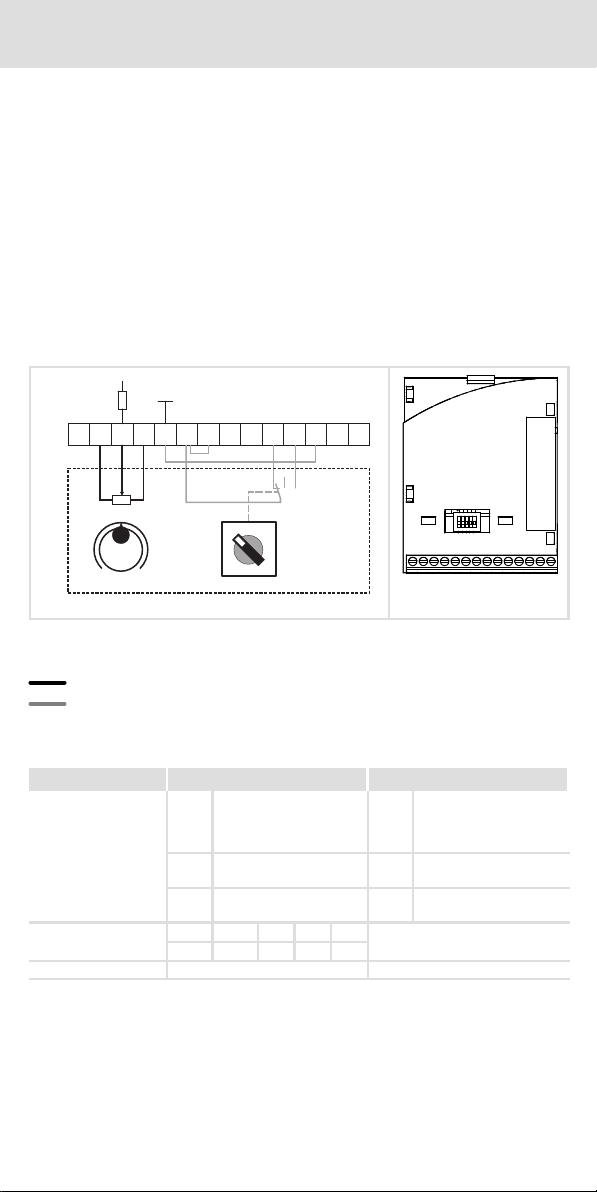
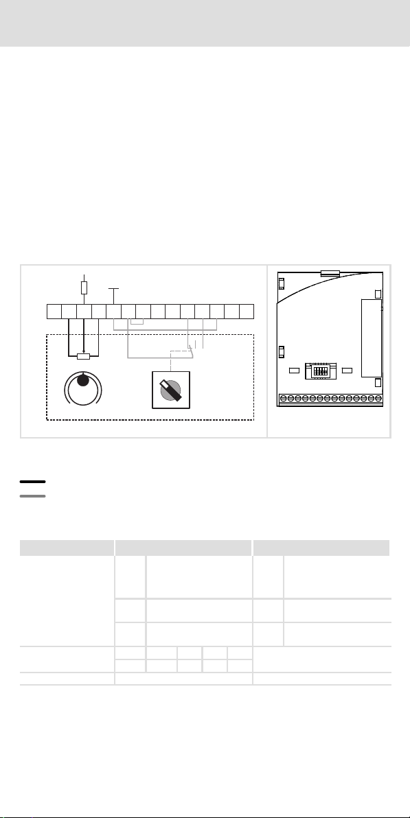
Wiring with Application−I/O
Setpoint selection through potentiometer and reversal of direction of rotation through
switch
Description of the functionality
ƒ Deceleration after STOP along the quick stop ramp (C0105).
ƒ Deceleration and acceleration after a reversal of the direction of rotation along
ramps C0013 and C0012.
For this, the following is required:
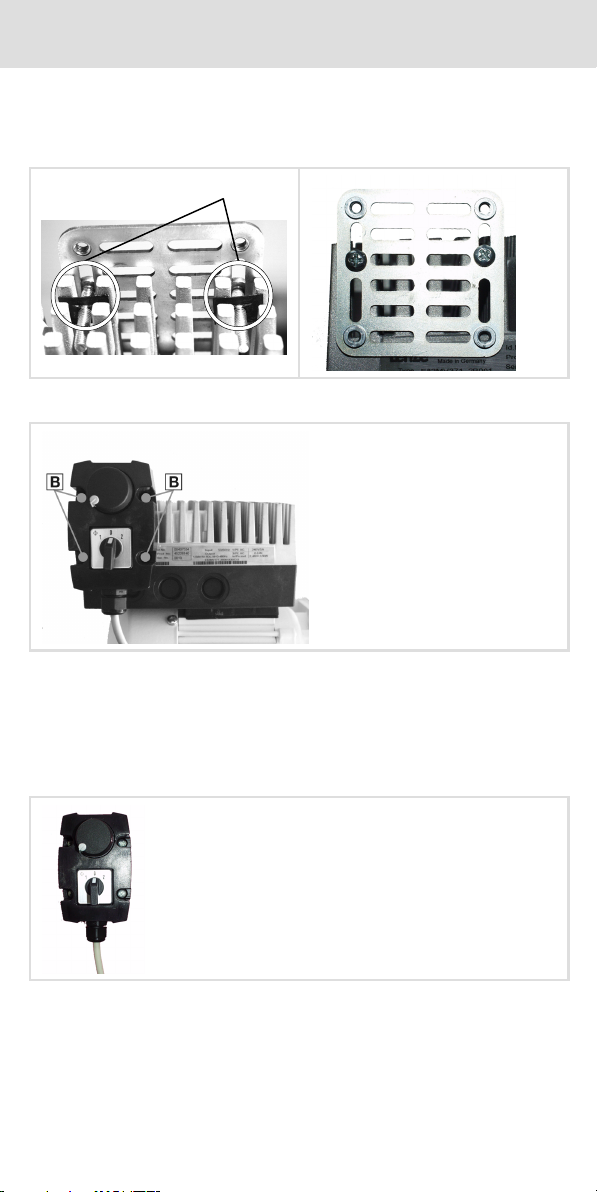
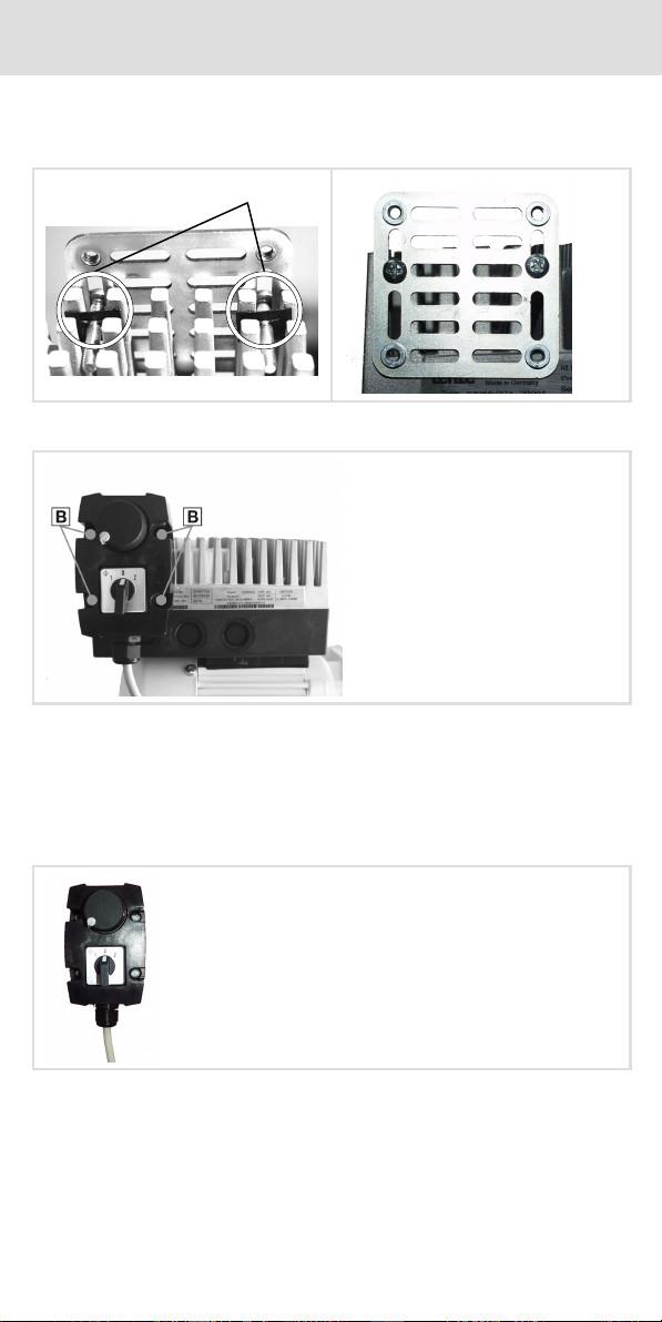
1. Connect the switch/potentiometer unit to the Application−I/O.
2. Configure hardware and software of the motec for a setpoint range of 0 ... 5 V:
– Adapt the jumper position at the function module.
– Adapt C0034.
3. Configure two digital inputs with the signals CW/QSP and CCW/QSP
Example for terminal configuration C0007 = −16−
7 7
X3
>100k
10k
A4 59 20 28 E1 E2 E3 E4 E5 E6
A2A1
GND
+5V
1=CW 2=CCW
0
min max
2U 2I 62 63 9
1I
1U
>100k
GND
A
C
B
D
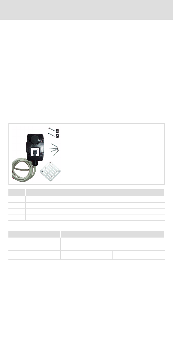
E82ZBU03
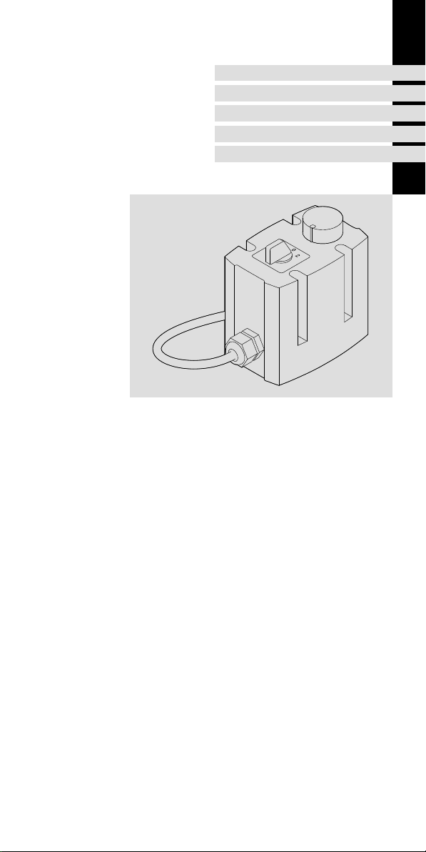
Switch/potentiometer unit
Wire bridge
Setpoint selection possible via X3/1U or X3/2U
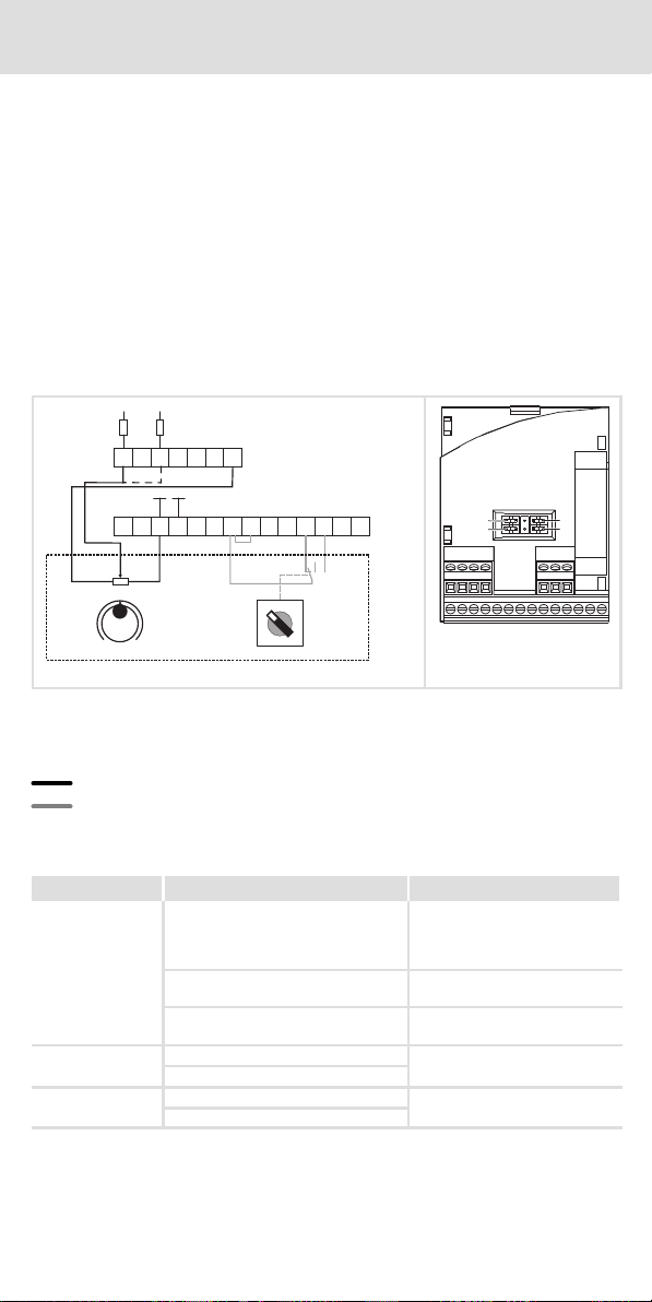
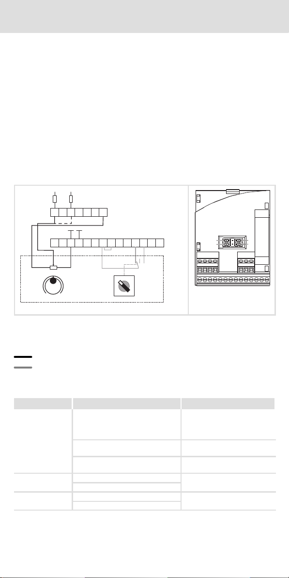
Wiring for setpoint selection through potentiometer
Wiring for reversal of direction of rotation through switch
CW CW rotation
CCW CCW rotation
Setpoint selection Change of direction of rotation
Terminal
assignment
X3/1U
or
X3/2U
White wire X3/20 Yellow wire
DC supply +20 V
Wire bridge to X3/28
Controller inhibit" (CINH)
X3/9: Green wire X3/E3 Grey wire = CW rotation
(CW/QSP on X3/E3)
X3/7 Brown wire X3/E4 Pink wire = CCW rotation
(CCW/QSP on X3/E4)
Jumper position Setpoint on X3/1U: Remove jumper A
Setpoint on X3/2U: Remove jumper B
Parameter setting Setpoint on X3/1U: C0034/1 = −0− C0007 = −16−
Setpoint on X3/2U: C0034/2 = −0−