Leprecon ULD-340DMX-HP User manual

1
ULD-340DMX-HP USER’S MANUAL

2
Table of Contents
Endplate Illustration – ULD-340DMX-HP
..........................................................
3
1)
Introduction........................................................................................................
4
2)
Specifications..................................................................................................... 4
Power
Connection ............................................................................................... 4
Ambient Temperature
.......................................................................................... 4
Power
Capacity ................................................................................................... 4
Control input
....................................................................................................... 5
3)
Installation ......................................................................................................... 6
Mounting............................................................................................................. 6
Power
Connection ............................................................................................... 6
Load
Connection .................................................................................................
6
4) Turning on
Power...............................................................................................
6
5) Front Panel Controls
.......................................................................................... 7
Resetting the ULD-340 to default values:
............................................................
7
Channel Mode
Menu
........................................................................................... 8
Status Menu
........................................................................................................
9
Configuration Data
.............................................................................................11
6) Error conditions
................................................................................................11
7)
Service
..............................................................................................................12
Service
policy.....................................................................................................12
Warranty
Information .........................................................................................12
8) DMX 512 Information
......................................................................................13
Connectors
.........................................................................................................13
Cable
type
..........................................................................................................13

3
Endplate Illustration – ULD-340DMX-HP
LED
DMX In
En
t
e
r
Menu
DMX Out
d 0
0
Data
In
ON
I
O
OFF
ON
I
O
OFF
Data Out
Line A
Line
B
ULD
Se
r
i
e
s
Breaker ‘A”
POWER INPUT CABLES

- 4 -
1)
Introduction
The new ULD series dimmer is designed to be a capable and reliable solution
for temporary and portable dimming requirements. With the menu-based
interface, the dimmer can be configured for different applications, including
stand-alone use without a controller. Default values can be restored at any
time, clearing the internal memory back to the standard values.
Please take a few minutes to review the specifications and operating features
of the ULD-340 dimmer.
The ULD-340 dimmer is designed for use with conventional incandescent
fixtures. Transformer loads, such as low voltage devices using a step-down
transformer, may require an additional load to be connected to the same
circuit to operate properly.
For operating florescent fixtures, see the section regarding Front Panel Controls.
2) Specifications
Power Connection
Unless otherwise indicated, your ULD-340 dimmer is designed for connection to
standard US power systems, 120 VAC 60 Hz. Lamp connections must be 120
V devices only. Line voltages over 135 VAC will trigger the overvoltage
protection circuit and shut off the dimmer pack.
Ambient
Temperature
The ULD-340 dimmer is designed for use in a cool, ventilated area. Ambient
air temperature must be less than 40 degrees Celsius, or about 104 degrees
Fahrenheit.
Power
Capacity
The ULD340 DMX is unique in the market of small portable dimmers. A single
breaker is used on the pack instead of individual fuses per each channel. As a
result, the limits of the dimmer are pack limits, not channel limits. The following
guidelines should be followed:
ULD340 DMX-HP – when plugged into a 100% duty-cycle service or a wall
socket in the USA
Pack Limit: 15 Amps (1800 watts) for each of the 2 power input cables, or 30
amps (3600 watts) total
Individual channel limit of 18 watts

- 5 -
Example 1: 15 watts on channel 1, 6 watts on channel 2, 18 watts on channel 3 and
nothing on channel 4
Power input cable A and breaker A control channels 1 and 2. The maximum wattage per power
input cable is 18 watts. You have 21 watts on the 2 channels (15 + 6 ) so the breaker
will trip. You will have to remove some lights.
Power input cable B and breaker B control channels 3 and 4. The maximum wattage per power
input cable is 18 watts. The maximum wattage per channel is also 18 watts, so an 18 watt
load will be OK, as there is no load on channel 4 and the pack is on a 1 % duty cycle service.
ULD340 DMX-HP – when plugged into a normal wall outlet in Canada
Pack Limit: 12 Amps (1500 watts) for each of the 2 power input cables, or 24
amps (3000 watts) total
Individual channel limit of 15 watts
Example 2: 13 watts on channel 1, 6 watts on channel 2, 15 watts on channel 3 and
nothing on channel 4
Power input cable A and breaker A control channels 1 and 2. The maximum wattage per power
input cable is 15 watts. You have 19 watts on the 2 channels (13 + 6 ) so you will trip
the breaker.
Power input cable B and breaker B control channels 3 and 4. The maximum wattage per power
input cable is 15 watts. The maximum wattage per channel is also 15 watts, so a 15 watt
load will be OK on channel 3, as there is no load on channel 4.
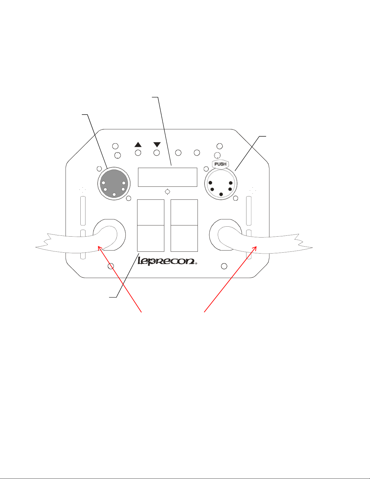
Control input
The ULD-340 DMX accepts DMX 512 1990 as specified by USITT. Reliable DMX
systems require cable rated for data communication at 250K baud; for this reason the
use of microphone cable is NOT recommended. DMX rated cables are available pre-
manufactured from your Leprecon dealer. For more information on the DMX standard
and acceptable cable, see the Appendix at the end of this manual.
For convenience, DMX in and out connectors are provided on the ULD-340DMX. This
allows easy connection to additional dimmer packs. The DMX standard allows up to 32
dimmers to be connected to a single DMX controller.
For proper operation, it is recommended that the last dimmer in the system have a
termination plug placed in the DMX Out connector. Termination plugs can be
purchased, or easily built by installing a 120 ohm resistor between pins 2 and 3 of the 5
pin XLR.

- 6 -
3) Installation
Mounting
The ULD340 is designed for vertical mounting. The top hanging bracket has a
pre-punched hole for a standard ½” pipe clamp mounting bolt. Using this
mounting point allows the dimmer to be mounted with the power cords, DMX
display and DMX control connectors facing downward.
The ULD340 dimmers are passively cooled, using no internal fans. The heat
generated by the dimmer is dissipated by the extruded metal chassis, and the
airflow through the chassis vents. For this reason, mount the dimmer so that air
is free to circulate around the dimmer. The dimmer should be mounted with at
least 12 inches of clearance between the dimmer and any ceiling or obstruction
above the dimmer that would block air circulation.
Power Connection
Leprecon LD340 series dimmers are supplied with line cords which have
standard TLG plugs attached. Each line of the LD340 should be connected to a
service capable of supplying 15 amps @ 100% duty cycle and protected by a
properly sized circuit breaker.
If you have any questions about the suitability of the power circuit that you
intend to use with the LD340 dimmer, consult with a qualified electrician.
Load Connection
Lamp loads are plugged directly into the outlets on the body of the dimmer.
4) Turning on Power
The ULD-340 has two line cords and two circuit breakers. The line cord and
breaker to the left on the endplate, labeled ‘A’, supplies power for channels 1
and 2, as well as the internal power supply for the control electronics. Line cord
and breaker ‘B’ supplies power to channels 3 and 4.
Power applied to the dimmer is indicated by an internal green indicator in each
of the breakers. If the breaker is on, but not lighted, there is no power to the line
cord. Turning on breaker ‘A’ will also light the red LED display.
Note:
The unit can be Reset to original factory settings by depressing and holding the
ENTER switch while turning on the first breaker.

- 7 -
5) Front Panel Controls
The ULD-340 dimmer uses a 4 digit display and four entry switches to set pack
functions, and display operating status.
Resetting the ULD-340 to default values:
The unit can be Reset to original factory settings by depressing and holding the
ENTER switch while turning on the first breaker.
Address
Menu
When the dimmer is first turned on, the display shows the starting channel
address of the ULD-340. This is the DMX address that will control the first
channel of the pack.
When there is no DMX input, the channel number is preceded by the letter A for
address:
A
.
004
When valid DMX is detected, the letter ‘A’ is replaced with the letter ‘d’ for DMX:
d
.
004

- 8 -
The UP/DOWN keys change the value for the start address. The ULD-340 uses
the changed value immediately and permanently saves it after 10 seconds or if
the Enter or Menu key is pressed.
After power on, the ULD-340 remains in the Address Menu in its simple interface
mode. To go to any other menu requires the user to hold the MENU key for about
5 seconds.
Channel Mode Menu
The Channel Mode Menu allows setting the mode of each dimmer channel.
This mode is indicated by the letter ‘c’ in the display:
c2:
Ln
Set the mode for the displayed channel by pressing the UP/DOWN keys. The
possible channel modes are:
Mode Description
Ln Linear output. Standard dimmer channel.
Nd Non- dim. Fader input above 60% turns on channel to 100%. Input
below 40% turns off channel.
FL
F
lorescent output. Dimmer does not begin to turn on until 20%.
00-FF
F
ixed output level. Values are 0, 10-99 and FF. FF is 100% output.
After changing the mode the colon will blink to indicate new data has been
entered. Press the ENTER key saves the change, and advance to the next
channel.
The LD-340 returns to the Address Menu automatically after 4 seconds if no
keys are pressed in the Mode Menu.

- 9 -
Status Menu
When the ULD-340 is in the Channel mode, pressing ‘MENU’ again will start the
Status mode. When Status mode starts, the state of each channel will be shown
in sequence, with the display cycling from Channel 1 to Channel 4, then
automatically cycle back to channel 1. This automatic cycling is indicated by the
flashing colon.
The Status Mode first displays the current input state of the dimmer channels 1-
4. If valid DMX is present, the letter ‘d’ is displayed, followed by the DMX value
for the channel:
d1
:
00
If there is no DMX present, the ‘d’ letter will disappear, and a ‘-‘ will be shown
instead:
-1
:
00

- 10 -
d1:00
Once the input levels for all dimmer channels have been shown, the display will
then indicate the output level for each channel. This is indicated by the letter ‘o’
in the display, followed by channel number, followed by output level. Output will
be shown as a percentage, with 100% indicated b the letters ‘FF’
Pressing the ENTER, UP or DOWN keys stops the auto cycle mode and enters
manual mode. Pressing MENU toggles between auto and manual cycle modes.
In manual mode the menu steps through its displays when the UP or DOWN
keys are pressed. The colon is steady in manual mode.
o1
:
FF
If a channel has been set to a fixed level in the Channel menu, the output status
will reflect that level. In this case, the input for channel 1 could be zero, but
there could be a non-zero output level.
Status Letter Description
– No input detected
d DMX is input source
o Output level
F Output Fault – Overtemp or Overvoltage shutdown
Note:
The unit can be Reset to original factory settings by depressing and holding the
ENTER switch while turning on the first breaker.

- 11 -
Configuration Data
If you press the Menu button while in the status display, various factory
configuration data will be seen. These features are not fully defined at this
point, but include software version, power configuration, and analog calibration
data for the microprocessor.
6) Error conditions
The ULD-340 will protect itself if the line voltage or operating temperature
exceeds safe limits. In these cases, the dimmer will turn off all channels, and
display an error message on the display:
Er
:
01
Error 01 is displayed for an overtemperature condition.
Error 02 is displayed for an overvoltage condition.
The dimmer will return to normal operation once the fault is corrected.
NOTE: Extended operation with Overvoltage applied can cause damage to the
dimmer power supply.

- 12 -
7) Service
Service policy
The LD340 DMX is designed for a long, trouble free life. If you suspect that you
have a dimmer problem, the first step is to check all other system components
and connections. The easiest test is to substitute a known good dimmer in place
of the suspected unit. Make sure that the DMX start address is set to the same
value.
Specific problems and solutions are listed below:
Problem Indication Solution
no power breaker not lighted check incoming power
No response to DMX Display shows D, but
no output
Level set in Channel menu
Clear dimmer and recheck.
Shorted load breaker trips repair instrument or cable
No DMX signal Display shows A Check cable and controller
SCR failure Channel stuck at full refer to service center
Over Temp Error 02 Check airflow
Over Voltage Error 01 Check power wiring
Overload breaker trips check wattage of loads
Table of contents
Other Leprecon Dimmer manuals
Popular Dimmer manuals by other brands

Saxby Lighting
Saxby Lighting 101345 instruction manual

Acclaim Lighting
Acclaim Lighting AL-DIMMER-3F HP User instructions

City Theatrical
City Theatrical SHoW DMX Neo D4 user manual

QUBINO
QUBINO ZMNHWD1 user manual

Leviton
Leviton Decora Smart DWVAA Getting started guide

VOS
VOS IntelaVoice 98009 instruction manual