V+ V+
CW- CW-
WW- WW-
V+ V+
CW- CW-
WW- WW-
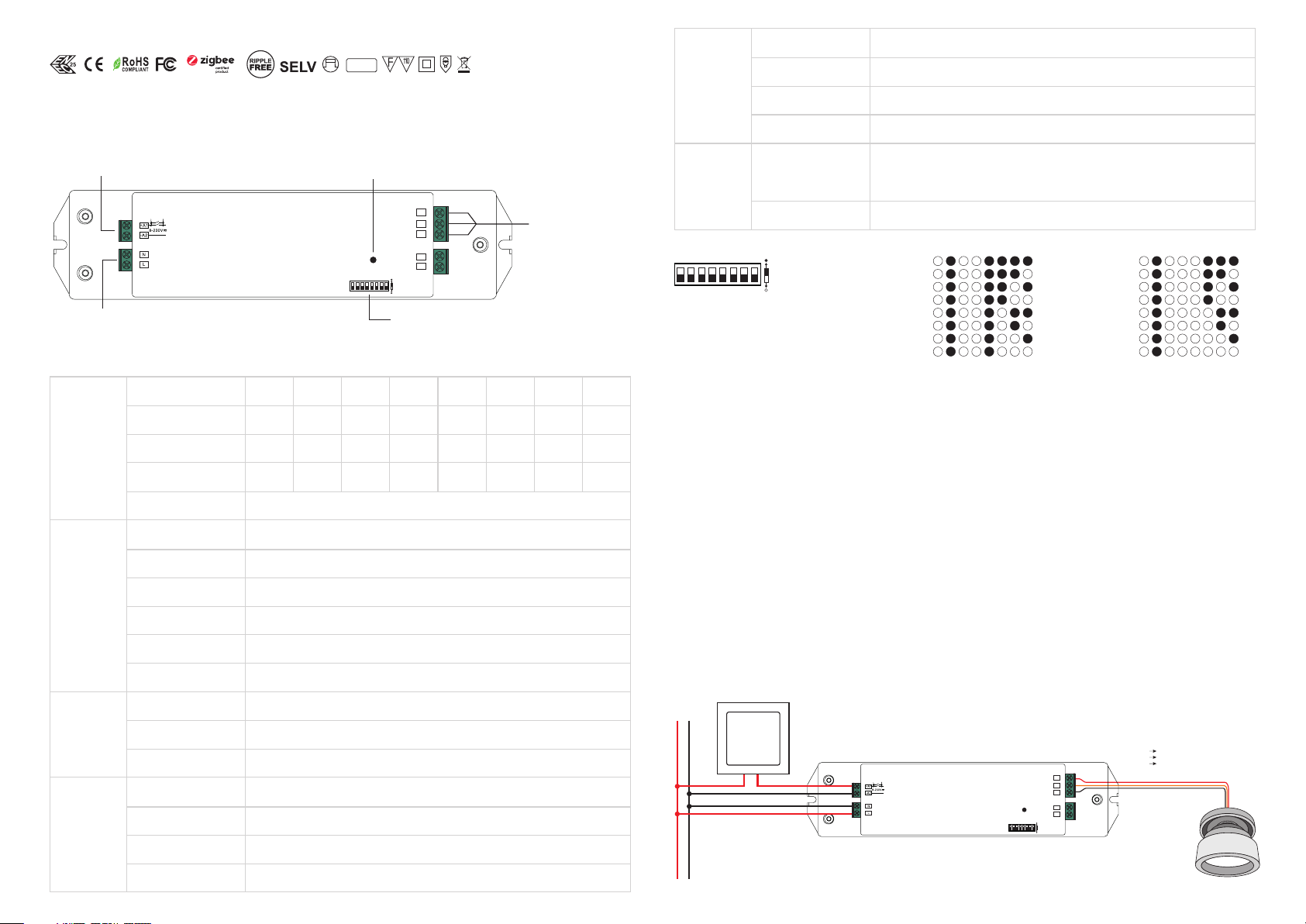
AC Power
50/60Hz
Operation
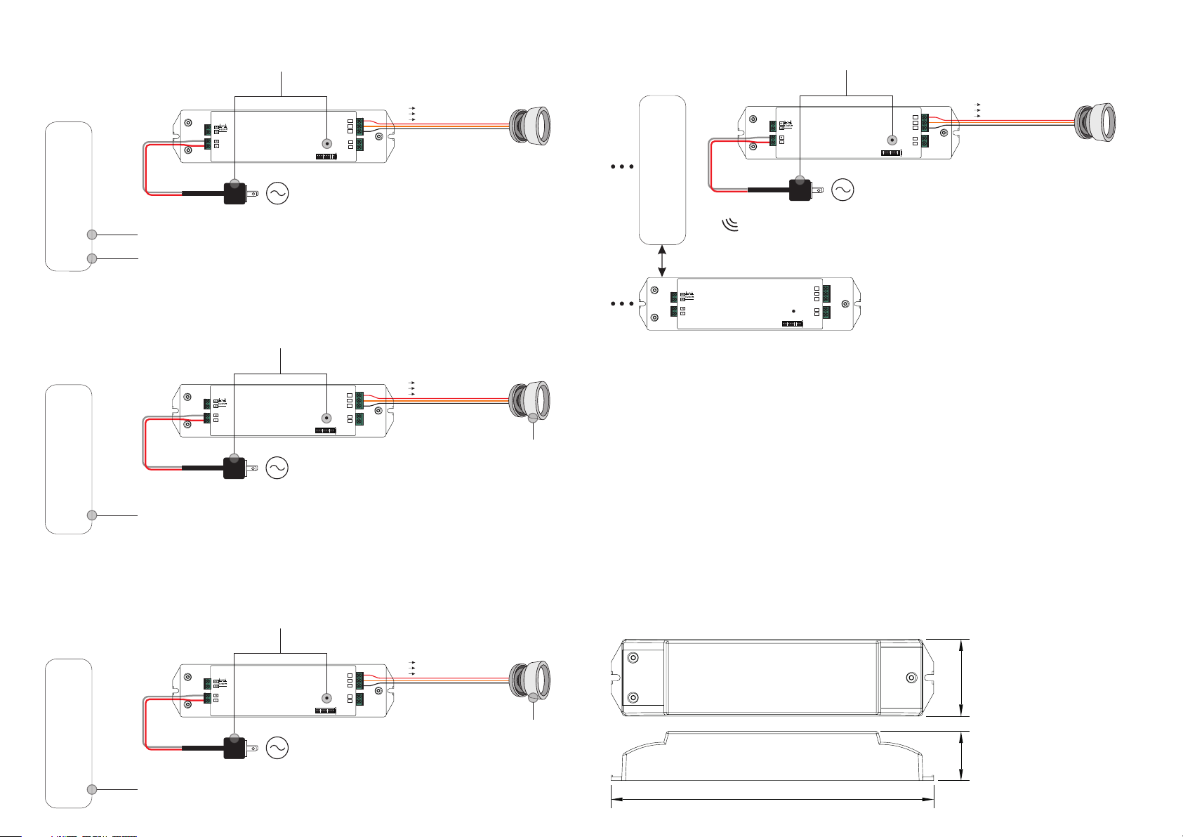
1.Do wiring according to connection diagram correctly.
2.This ZigBee device is a wireless receiver that communicates with a variety of ZigBee compatible
systems. This receiver receives and is controlled by wireless radio signals from the compatible ZigBee
system.
3. Zigbee Network Pairing through Coordinator or Hub (Added to a Zigbee Network)
Note: 1) Directly TouchLink (both not added to a ZigBee network), each device can link with 1 remote.
2) TouchLink after both added to a ZigBee network, each device can link with max. 30 remotes.
3) To control by both gateway & remote, add remote and device to network first then TouchLink.
4) After TouchLink, the device can be controlled by the linked remotes.
Step 1: Remove the device from previous zigbee network if it has already been added to, otherwise pairing will
fail. Please refer to the part "Factory Reset Manually".
Step 2: From your ZigBee Controller or hub interface, choose to add lighting device and enter Pairing mode as
instructed by the controller.
Step 3: Re-power on the device to set it into network pairing mode (connected light flashes twice slowly), 15
seconds timeout, repeat the operation.
Step 4: Connected light will blink 5 times and then stay
solid on, then the device will appear in your controller's
menu and can be controlled through controller or hub
interface.
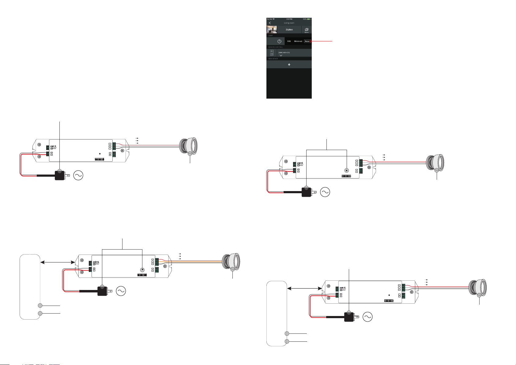
5. Removed from a Zigbee Network through Coordinator or Hub Interface
From your ZigBee controller or hub interface, choose to delete or reset the
lighting device as instructed. The connected light blinks 3 times to indicate
successful reset.
Step 4: There shall be indication on
the remote for successful link and
connected light will flash twice.
< 10cm
Zigbee
Remote
Step 2: Bring the remote or touch panel within 10cm of the lighting device.
Step 3: Set the remote or touch panel into Touchlink commissioning,
please refer to corresponding remote or touch panel manual to learn how.
6. Factory Reset Manually
Note: 1) If the device is already at factory default setting, there is no indication when factory reset again .
2) All configuration parameters will be reset after the device is reset or removed from the network.
Step 1: Short press “Prog.” key for 5 times continuously or re-power on the device for 5 times continuously if
the “Prog.” key is not accessible.
Step 1: Re-power on the device to start TouchLink Commissioning, 180 seconds timeout, repeat the operation.
7. Factory Reset through a Zigbee Remote (Touch Reset)
Note: Make sure the device already added to a network, the remote added to the same one or not added to any
network.
Step 2: Bring the remote or touch panel within 10cm of the lighting device.
Step 3: Set the remote or touch panel into Touch Reset procedure to reset the
device, please refer to corresponding remote or touch panel manual to learn how.
Step 2: Connected light will blink 3 times to indicate
successful reset.
Step 4: There shall be indication on
the remote and connected light
flashes 3 times for successful reset.
< 10cm
Zigbee
Remote
AC Power
50/60Hz
AC Power
50/60Hz
AC Power
50/60Hz
V+ V+
CW- CW-
WW- WW-
V+ V+
CW- CW-
WW- WW-
4. TouchLink to a Zigbee Remote
Step 1: Method 1: Short press “Prog” button 4 times (or re-power on the device 4 times) to start Touchlink
commissioning immediately, 180S timeout, repeat the operation.
Method 2: Re-power on the device, Touchlink commissioning will start after 15S if it’s not added to a zigbee
network, 165S timeout. Or start immediately if it’s already added to a network, 180S timeout. Once timeout,
repeat the operation.
LED+
WW-
CW-
ZigB ee LED Driver
SELV
Prog k ey
AC INP UT
NC
NC
1 2 3 4 5 6 7 8
Pus h Switc h Input
LED+
WW-
CW-
ZigBee LED Driver
SELV
Prog k ey
AC INP UT
NC
NC
1 2 3 4 5 6 7 8
Pus h Switc h Input
LED+
WW-
CW-
ZigBee LED Driver
SELV
Prog k ey
AC INP UT
NC
NC
1 2 3 4 5 6 7 8
Pus h Switc h Input
LED+
WW-
CW-
ZigBee LED Driver
SELV
Prog k ey
AC INP UT
NC
NC
1 2 3 4 5 6 7 8
Pus h Switc h Input