LEROY-SOMER [ Installation and maintenance |
________
4803 en-2011.12/ b
LSA 42.3 - 4 POLES
ALTERNATORS
CONTENTS
1 - RECEIPT
............................................................................................................................
4
1.1- Standards and safety measures
................................................................................
...4
1.2 - Inspection
.......................................................................................................
4
1.3 - Identification
................................................................
....4
1.4-Storag e
..........................................................................................
4
1.5-Application s
..................................................................................................................
4
1.6 - Contraindications to use
...............................................................................................
4
2 -TECHNICAL CHARACTERISTICS
....................................................................................
5
2.1 - Electrical c aracteristics
...............................................................................................
5
2.2 - Mec anical c aracteristics
...........................................................................................
5
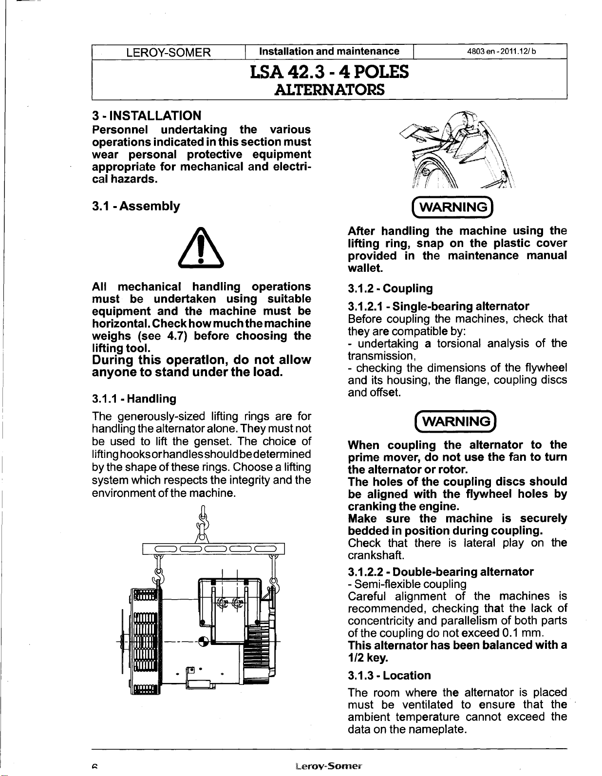
3 - INSTALLATION
..................................................................................................................
6
3.1 -Assembly
......................................................................................................................
6
3.2 - C ecks prior to first use
................................................................................................
7
3.3 - Terminal connection diagrams
...................................................................
7
3.4 - Commissioning
..................
10
3.5 - Setting up
....................................................................
10
4 - SERVICING - MAINTENANCE
...................................................................
11
4.1 - Safety measures
.........................................................................................................
11
4.2 - Routine maintenance
..................................................................................................
11
4.3 - Fault detection
..................
.........................................................................................
11
4.4 - Mec anical defects
....................................................................................................
12
4.5 - Electrical faults
...........................................................................................................
12
4.6 - Dismantling, reassembly
............................................................................................
14
4.7 - Installation & maintenance of t e PMG...
....................................................................
16
4.8 - Table of c aracteristics
...............................................................................................
16
5 - SPARE PARTS
............................................................................................
18
5.1 - First maintenance parts
..............................................................................................
18
5.2 - Tec nical support Service
...........................................................................................
18
5.3 - Exploded views, parts list and tig tening torque
.........................................................
19
EC declaration of incorporation
.........................................................................................
22