Leshine W-023 User manual

Electronic
Pet Fencing System 023

Electronic Pet Fencing System
This hidden HT-023 fencing system is among the most reliable, cost€fficient
pet containment systems available today. A buried wire transmits a harmless
Gdio signal. When you dog approaches the boundary, the signal causes tte,
dog's collar receiver to deliver a warning Oeep Rret. tt youidog onfinues
closer to the boundary, the system will issue a mib sf,o"f. it you, Oog
continues further, the system will issue stronger shocks until your dfo returnl
to within the boundary your have set up_ your dog will naturjf seeito avoid
correction, and is @ntent staying within established boundaries.
Main Fealures:
. Pulsed Proportional Stimulu-The closer your dog gets to the
boundary, the more intense the shock will be;
. Progressive Tone Stimulu-A waming tone will be issued firet, lhen
o shock slimulus ofter4-l O seconds. lf yar dog continues to move closer
to the boundory the shock stimulus will progressive.
. Variable Field Width Controt-Allows you to precisely @ntrot the
width ofthe signat field;
. Audible and Visual Wire Break tndi€toE-_-Shoutd your buried wire
ever break, a loud sonic alam will sound arcompanied by a flashing
light;
. Speed Detect Anti-Run through-The faster your dog is moving, the
quicker the higher level of intensity is issued;
. Built-in Lightning protection-protects transmitter frcm power surges
@used by lightning strikes:
o

. Muatiple Colhr Opmdor}-4dd as many @llars as you like to contain
as many animls yd haw. Thffi is no limit to the number of @llaG it
€n @ntrol.
. Up to 5000 squaE metse E lg€ (@r 1 .2 are).
Psckage ContenB:
. 1 xlnd@rmll-mountedtsa|Mitts;
. lxPilerplug;
. 1 x Adjustable lBeiver cdlar:
. I x 6 Vott battery for @lht
. 1 x boundary wire of 300 rets6;
. 2 x Exba metal @ntact pdnts;
. 20 x TEining flag6;
. lxTestbulb;
. 4xsmre;
. lxUse/smanual.
Other items you may ns"d:
. ScrewdriveE
. Straight edged spade or a lawn edger;
. Wire stipping plieE:
. Electri€l tape;
. Waterpmfing @mpound (e-9. sllicone eulk);
. Patching @mpound for your type of driveway or sidewalk;
. PVC pipe if crossing a gravel or dirt driveway, pond or lake;
. Pencil, Ruler or Prcfactor;
. Drillwith drill bit or ma$nry bil if drilling thmugh wood or @ncrete;
. Additional Boundary WiE.
CAUNON
Please take a few minutes to read the instruclion man@l priq to your fiBt use.
For best results, follN thes important ruls:
. Th6 sl€clronic dog cdlar b inteoded qly for m m dogs.
. A low battery may €us inE mitlent opeElim. DO NOT USE if you
suspec{ a low batbry.
. Allow your dog to get usd to th6 @ilar before you begin haining. you
want your dog lo a@pt the @llar as part of a Eutine, not to a$ociate
the @llarwith @rection.
. DO NOT leave the collar on your dog for more than 12 h@G per day.
. NEVER perfom set-up prc@dures when the @llar is on your dog.
. An electrcnic @llar should only be 6ed under dos supervision by the
dog's owner.
r KEEPOUTOFTHE REACH OFCHTLDREN.
. Read all instructions before using this prcduct.
IMPORTANT
Realize that bmuse individual dogs have unique tempemments, lhere is no
way of knwing how your dog will react to its intoduclim lo this prcduct. For
the safety of your dog, initial faining shoutd take pla@ using a long teash to
keep you in @ntrol of the situation. Also Ealize that an aggcssive animal
could tum against th€ handler upon reeiving the stimulus. Therefore, if you
f€el you dog has an aggre$ive behaviqr and/or il has a hisbry of aggresive
behaviour, you should @nsult a @rtified animal behaviourist bafore using this
produc{.
sEcTroN 1
INSTRUCTIONS FOR SETTI}IG UP YOUR COI{TAINIf,ENT SYSTET
STEP I
PREPARE A LAYOUT OF YOUR CONTAINMENT AREA
A. D6i9n and Dmw DiagEm
PrepaE a diagram of the area you want io mntain your dog. A diagEm will
help to avoid unforeseen obstacles. lnclude the lmtion of hous, drivmy,
pond, gaden, swimming pool, etc. It your neighbou has a @ntainment system
installed, ml* the l@tion of the buried wire on your diagEm.
B. Contact tltlltly Company
Contact your utility compani6 to mark any buried utility lin6s_ Be sure to
include the buried lines on your drawing be@use lhe* utility lines will afecl
the placement of you wire.
C. Deiemine Loetion of Wall TEnsmitter
The tansmitler €n be mounted to a wall near any standard 240_volt
household outet with the included screre. lt will wiihstand frezing
tempeEfures, but it is not waterproof. Thereiore, it is best to l@te the
tEnsmitter in an enclosed area. lnstall the transmitter at least thE ieet (we
onsider ten feet will be better) from any large metal obiects $cfi 6 breaker
boxes, waler heatere, metal ga€ge d@8, or washer and/or dryer. Whea
eo

installing the transmitter make sure the wire is not cut off or pinched by a
window, door or garage door. When drilling holes, make sure there are no
electrical wires, nails or screws inside the area you are drilling.
D, Determine the Exit Route ofYour Boundary Wire from the Transmitter
to the Outside Containment Area
Since your tEnsmitter must be mounted in an enclosed area to protect it from
the weather, give careful consideration on where the wire exits to the exterior.
Existing openings such as a window, door or utility line hole may provide easy
access to the outside. You may need to drill a hole through the exterior wall.
STEP 2
ADD PROPOSED WIRE LOCATION TO YOUR DMWNG
l\,!ark your diagram with the proposed lo@tion of your wire. This will provide an
easy referen@ as you install the wire. For the system to wo* propedy, the
wire must make one continuous loop. The signal is transmitted from one
terminal ofthe transmitter, through the wire and back to the other teminal.
Example lnstallation Diagrams
Keep pets sepaEted, or to
oll-".i""'lllil: _
Single loop - Back Yard Zone
This lets your pet have access to the lake or
other rear area_
Single Loop - Front Yard Zone
Your pet has run of the house and
back yard. Your pet has run olthe house and front yard
Keeps you. pet safely away from
gardens, pools, and other areas. You. pet has a 360 degree perimeter to .oam
within.
Dual Zones Open Back Zone
Your pet has run ofthe house and
back yard. Your pet has run of the house and front yard
oo
Basic Single Wire Zone
Double Loop - Back Yard Zone Double Loop - Front Yard Zone

Front & Rear BarrierZones Side Barier Zones
Your pet has full access to both Your pet has full affis to the frcnt or rear, bul
sides, but not to the ftont or rear. nol to lhe sides.
IMPORTANT NOTES FOR wlRE PLACE]IIENT:
. Do NOT run the wire less than 15 metres undsr any oc6iona. Do
NOT tum the field width knob to milimum whsn the wire is iust
over 15 metrea, otheruise it will bum th6 wall transmitter (lr3 of
6eld widih knob iurn is maximum). Wrc MUST be over 100 metrea
if you need to tum iho field width knob to milimum. lf rcquircd
wire is shorter than l0O metres, it will be safer to run double or
ev6n triple loop to make the layout wire over 100 metrss.
o Do NOT run the l@p within 2 mete6 parallel lo elechi€I, telephone,
Gble TV, or other buried wire in the yard.
. Do NOT run one section of wire within 3 mete6 of another section or
the signal may en@|.
. Do NOT run your wire within 3 meteE of any adja@nt @ntainment
system's wire.
r Do NOT run your wiB witiin 3 @nti-meteE of any steels baE under
conrete grcund otheruise signal strength will be redued.
STEP 3
ESTIMATE THE AMOUNT OF WRE NEEDED
HT{23 model includes 300 metres of boundary wire. lt €n enclose an area of
over 1.2 acres.
The amount of wire needed is detemined by several facto6:
(a)Total area to be contained:
(b)Using a double loop. This reouires twice as much wire_
(c)Size of the signal ,ield. The signal field is the distance from the wire to the
pla@ where the mllar receiver firsl activates. A 3 to 4 metec wide feld is
prefered.
STEP 4
INSTALL THE WALL TMNSMITTER
lnstall the wall lransmitter close to a standard 240-volt household ouflet. Do
not plug the tEnsmitter to the outlet until the boundary wire is in pla@.
IMPORTANT NOTE: We re@mmend that you unptug the transmitter and
disconnect the fene wire during lightning stoms.
If builde {ife &d,a 1o!d
s@i@lam nll so@d
STEP 5
LAY OUT THE PERITETER wlRE
IMPORTANT NOTE: Do NOT bury the wire untit you have tested the system
and are sure it is working properly. Do NOT nick or scmpe the wire during
installation. lmproper fu nction may result.
1. Use your drawing as a refe€n@. Begin laying the wire aDund the perimeter
of your @ntainment area to form a @ntinuous loop. Use gEdual turns at the
@meE with a minimum of lmeter radius. This provides a more @nsistent
signal Iield.
2. lf you are using more wiE than initially supplied with your @ntainment
system, the wire connections must be waterproof to provide a sealed
connection between the wires. Do not use electri@l tape or twisted wire nuts.
This will @use an intermittent signal or disam the system.
3. Continue around your perimeter until you return to the start ofthe loop.
4. Cut the wire.
o
o

STEP 6
CONNECT THE PERIMETER WRE TO THE WALL TRANSMITTER
The wire from the perimeler to the wall transmitter should be twisted lo €n@t
the signal. This allows the dog to cros the area without rmiving a @rection.
It also elimlnates posible interferene from elechi€l wires, etc.
1. Measurc the distane from the wall tmnsmitter to th€ edge of the perimeter
wire.
2. Beeue twisting the wire demass the length of the wie, multiply the
dislan@ by 1Y2.
3. MeasuE and @t two wires of equal lengths of the above nieasurement.
4. Hold the two ends of the wiB side by side and twist thm together. The
wiEs en be twisted manuaily until the twists are 6 to i2 cm apart. The tighter
the wire is twisled the better the signal @n@llation.
5. Pull the twisted wic to the perimeter loetion of the two ends of your
boundary wire loop. Spli@ lhe ends of the lwisted wire to the ends of the
boundary wire ONLY with waterproof splies.
6. Put the twisted wiEs through the existing opening or ddlled hole so it €n be
@nnected to the transmitter.
7. Strip off about 1 cm of insulation ftom $e end of each twisled wire_
8. lnsert the wires into the teminals ol the transmitter.
9. Plug the power adapter into a standard 240-yolt household ouflet.
'10. Connect the power adapter to the transmitte/s power port.
STEP 7
VERIFY TRANSMITTER IS FUNCTIONING PROPERLY
To veriry the transmitter is functioning prcpedy, look for OK and power lights
on the tEnsmitter. When both of them tum green, it means the tEnsmitter is
receiving power, both wires are @nnected, and the wire forms an unbmken,
@ntinuous l@p. lf the Break light tums red, it means that one or both wires arc
rct prcperly onnected or both wires are mnnec{ed but the wire is broken.
Corect the prcblem and retest.
STEP 8
SET UP YOUR COLLAR RECETVER
lnserl 6V 41R44 battery in the @ltar re@iver following the positive (+) and
negative G) signs inside the battery @mparfnent. tn@rect instailation @uld
euse permanent damages to some elect onic parts. When the indi€tor light
tums green, it mmns the @llar reeiver is working properly. When the indicaior
light lums red, it means battery is running dom and needs to be eplaged.
,.,.","f,Pffi.*,
IMPORTANT NOTE: Do NOT ptace the @llar €eiver on your dog unijt the
@ntainment system has been tested and the signal fietd adjusted.
STEP 9
TEST THE GONTAINMENT SYSTE]II
DO NOT TEST THE CONTAINMENT SYSTEM WITH THE COLLAR
RECEIVER ON THE DOG. You must manually test the @ntainment system to
verify lhat the signal is propedy transmitt€d though the wiE. U* the supplied
lest light.
Select a section of slEight boundary wirc that is at least 50 feet long. Attach
the supplied test light to the receiver prcbes and hold the ollar re@iver at your
dog's neck height. Slowly walk the @llar toward the boundary wire. Listen ior
lhe waming tone and watch for the test light to light. The wider you @n make
the @ntainment field, the less chance your dog en run thrcugh. Adjust the
FIELD WDTH as nee$ary and test again.
Test in a number of difierent areas until you are stislied there are no wiE
breaks and the system is functioning prcperly.
Next walk all around the "safe" part of the yard to ensure ihere are no stray
signals, particularly near the twisted wlre 6ming frcm the trarsmitter. Tesl
@llar in and around the inside of the house as well. Signals fmm Cable TV,
eloctiel or telephone lines en "couple,' Busing stmy sjgnals inside and
outside th€ house that €n ac{ivate the dogt @llar accidentally. lf you do
encounter tiis phenomenon, your boundary wire is probably too dm to thes
outside lines and will need to be moved or modified. Containment @llaE
should not be worn inside the house.
STEP 10
ADJUST THE SIGNAL FIELD WDTH
The signal field is the disian@ from the wire to the plac where th6 6llar
re@iver fi6t aclivates. The Fietd Width Knob adiusts the size of the sigml fietd,
o
o

not the @rection intensity. Tuming the knob clmkwise increases lhe signal
field width; tuming it munter-delsis dereases it. Tuming the knob
@mpletely @unter-dockwise switches off the lransmitter power.
Fdlry the instructions in SteQ 10 to test the siqnal fietd width. Walk the entire
Qerimeter to be suc that the signat fied is @nsisteat thrcuqhout ys(
$fik{afi€*.rs.\\ss$r*,5fi*.*r$r*eEtffi*Enffi]]w 6}tTiem m
either side of the wire (creating a 4 meter wide field). A 3 to 4 meter wide field
is prefered. The wider the signal feld width, the les chan@ that a dog @n
run through he field.
IMPORTANT I{OTE: lf the Field Width knob is Emoved or the position of the
knob is altered by tuming it clockwise or @unter-clockwise, you must always
check the signal field for the desir€d setting. Refer to Step 10, test the
Containment System-
STEP,II
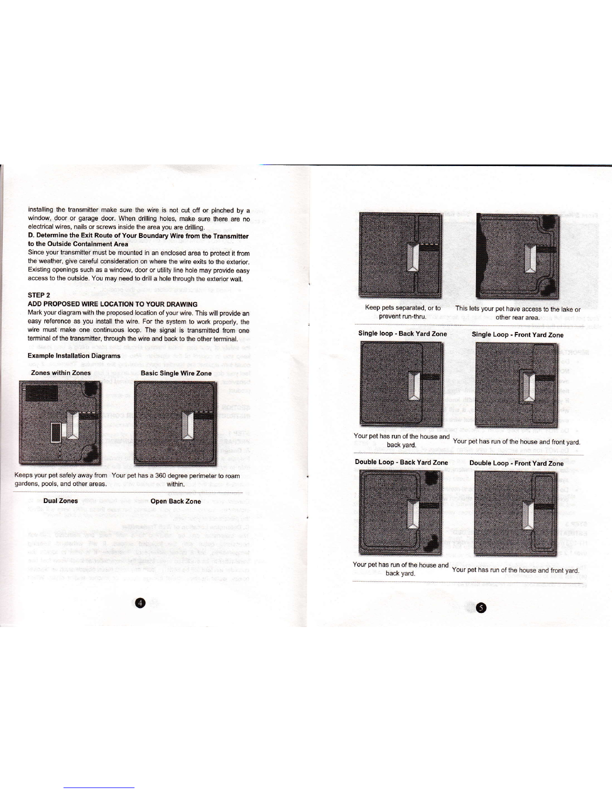
INSTALL THE BOUNDARY WRE
Tools Needed - StEight€dged spade, wire cutter / stipper, and standard
screwdriver. tf you plan to run the wire acrcss onsete, you will also need a
mulk gun, sili@ne eulking, and a cirular saw with a masonry blade.
Burying the wlrc - The wirc d@s not have to be buded, but for potection you
prcbably want to bury it at least one inch undergrcund. Start by digging about 7
to 10 m dep where the wire fiBt enteE the grcund near the Aansminer and
@ntinue arcund the path of the l@p wire.
Note: When @vering a large ar6a, you may wish to use a trenching machine
to cut into the grcund. Hwever, we mmmend that the wire be placed in the
trench by hand. A ommercialwiBplacing machine may break the wire.
Driveways / Sidewalks - When mssing an asphalt driveway, make a 2 cm
de6p @t across the driveway using a circular saw and masonry blade. place
the wire in the cEck and seal wilh asphalt sealant. On driveways and
sidewalks, if an expansion ioint is available, simply place the wire in the joint
and seal with an outd@r €ulk. When crcsing gEvel, bury the wire at least 7
cm deep U$ an old garden hose or plastic PVC piping to protect the wire. ln
water, andpr the wire with large rccks- Protect the wire with an old garden
hose or plas$c PVC piping.
STEP 12
INSTALL THE BOUNDARY TRAINING FLAGS
After installing the wire, retest lhe ontainment system as describ€d in Step 10,
Test the Containment Syst6m. Vedry that the signal field width is @nsistent by
following the instructions in Step 'l 1. Adjust the Signal Field Wdth. As you are
relesting and verirying the system, install the boundary training flags. Pla@ the
flags where the waming tone is fiEt heard as you apprcach the wire. The fags
should be pla@d at the edge of the signal field width, not directy on the wire.
This will add a visual oe lo the audio waming tone and help leur dog to leam
(\e \a\RdNl-
STEP 13
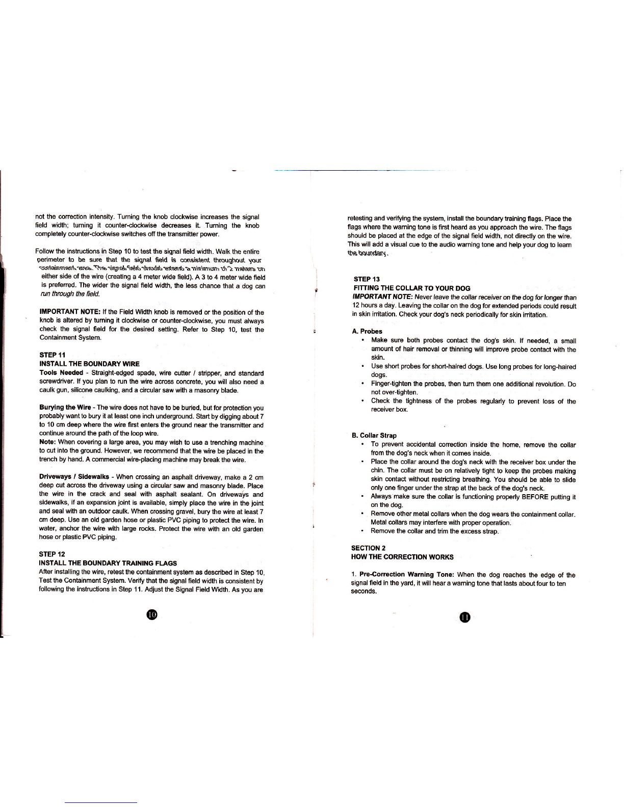
FITTING THE COLLAR TO YOUR DOG
IMPORTAT{T ltoTe Never leave the @,,ar Eeiver on the dog for longer than
12 houre a day. Leaving the @llar on the dog for extended periods @uld Hult
in skin iritation. Check your dog's neck periodi@lly for skin iritalion.
A. Prcbes
. Make suE both prcbes @ntact the dog's skin. lf neded, a small
amount of hair removal or thinning will improve prcbe @ntact with the
skin.
. Use shorl prcbes for short-haired dogs. Use long probes for long-haired
dogs.
. Finger-tighten the prcbes, then tum them one additional Evolution. Do
not over{ighten.
. Check the tightne$ of lhe prcbes regularly to pEvent toss of the
receiver box.
B. Collar Stmp
. To pBvent a@idental @trec.tion inside the home, Emove the @llar
faom the dog's neck when it @mes inside.
. Pla@ the collar arcund the dog's neck with the receiver box under lhe
chin. The @llar must be on relatvely tight to keep the probes making
skin @ntact without restricting breathing. You should be able to slide
only one finger underthe stap at the back ofthe dog's neck.
. Always make sure the @llar is functioning prcperly BEFORE putting it
on the dog.
. R€move other metal @lla6 when the dog wea6 the @ntainmenl collar.
Metal collars may interfere wilh pDper opeEtion.
. Remove lhe collar and tdm the excess stmp.
sEcTtolr 2
HOWTHE CORRECTION WORKS
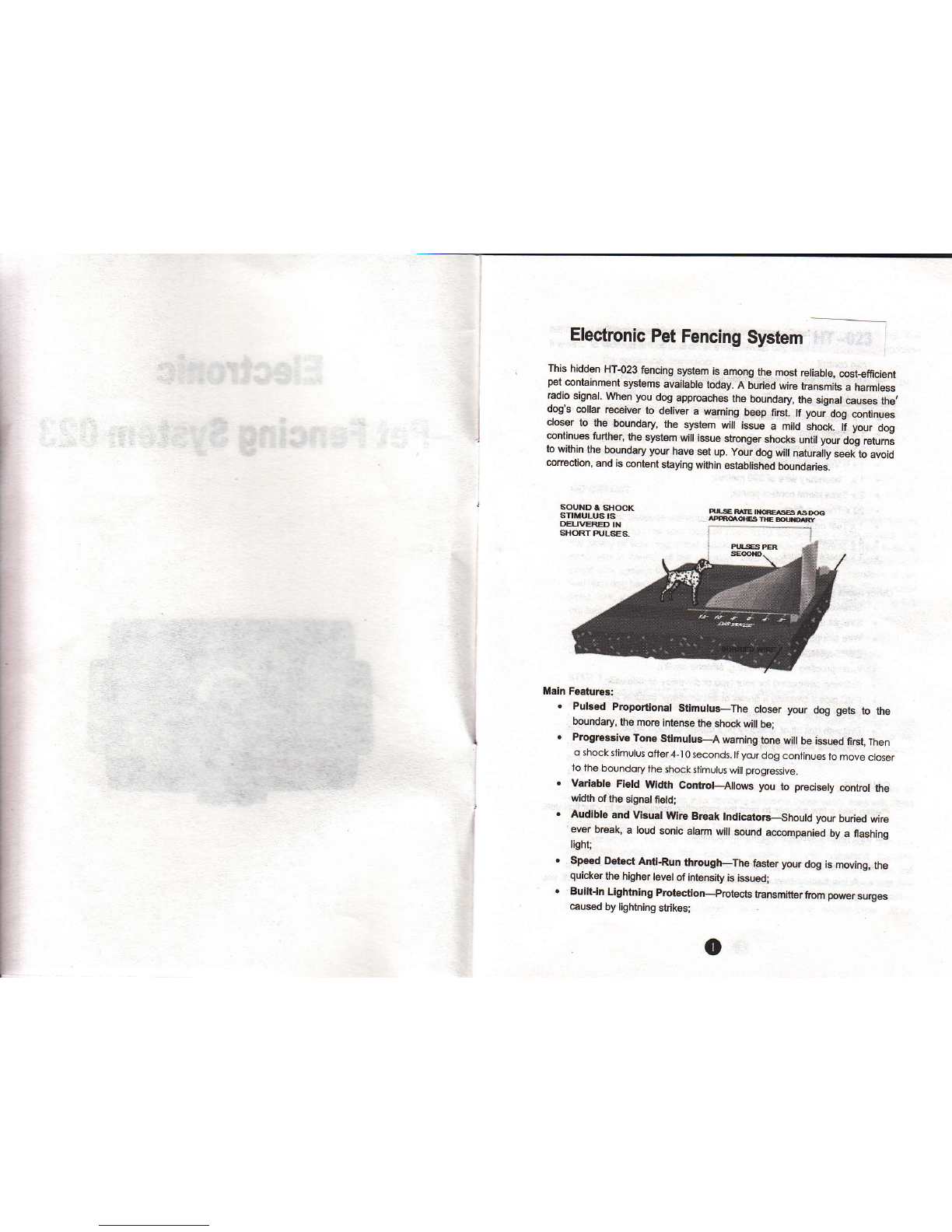
'1. Prc-Coretion Waming Tone: When the dog reaches the edge of the
signal field in the yard, it will hear a waming tone that lasts aboutfour to ten
smnds.
o
@

lf the dog does not rctum to the safe pan of the yard, it will l@ive a
@ntinuous @rection and slight sh@k until it retums to the sfe area.
2. Run-Thrcugh Prevonlion: The re@iver aulomati€lly inqeases the
@nection s the dog enteB the signalfield. The dog ennot'run thrcugh. the
signal field without re@iving a strong orrection.
sEcTtoN 3
TRAINING YOUR DOG
To get the mct out of your containment system when tBining, keep those tips
in mind:
. To prevent accidental @rec{ion inside the home, remove the @llar
from the dog's n$k when it @ms inside.
. Always make sure the 6llar is functioning properly BEFORE putting it
on the dog. Verify the system is operating prcperly and the field width is
appDpriate as described in Sectjon .1, Step 11. Adiust the Signal Field
width.
. Stay positive and playtul during the t€ining session.
. Keep training sessions brief. Never onlinue a session after your dog
has lost interesl. Take a break to rest or play.
. ALWAYS pEise your dog for good behaviour.
The ,ollowing steps outline a su@ssful tEining plan:
STEP I
FLAG TRAINING
'1. Tum the mll transmitter "otr so no @rections will be given to your dog.
2. Plae the @llar reeiver on your dog.
3- Pla@ a long lmsh on lour dog. play with you dog in the safe area of
the yard for 2-4 minutes. Do not allow your dog to run free or crcss the
flag lines.
4. Walk towards the flags. Reach down and shake a flag. Say'bad flag, in
a disapprcving tone.
5. Retum to tie @ntre part of the yard and play with your dog. Reward
with treats.
6. Repeat this exercise several times in various lo€tions of the yard.
STEP 2
THE FIRST CORRECTION
'1. You need lo reset the signaltield width before placing the @llar reeiver
on your dog. FdlM the instructions ouilined in Section 1, Step 11,
Adjust the Signal Field Width.
2. Pla@ the @llar rmiver on you dog in the safe area of the yard.
3. Pla@ a long leash on your dog. Ptay with the dog in the sfe area of the
yard.
4. Wdk towards the ltags. lf your dog tries to avoid the flags, prais and
ca$ure yourdog.
5. Repeat this step in other lo@tions of th€ yard.
6. Allow no more than thre corections in a day or seven in a reek. This
deponds on your dog's slress toleEne. Most dogs only re@ive a few
@redions during the haining phase; they respond to tone very quickly.
7. Reward your dog when it avoids the flags, even if a @rection is i$ued.
8. Play in the safe zone with your dog before ending this training sesion.
STEP 3
ON-LEASH PROOFING
'1. With the 6llar on you dog and lhe wall transmitter "on", play with your
dog (on leash) in the safe aea. After a few minutes of play, to$ a toy or
treat through the llags.
2. lf your dog runs through the ftags to chase the toy, wait for the starUed
respons and pullyour dog back into the safe area. praise and ward
Your dog.
3. Reinfo@ training by shaking a flag. Say'bad flag'with a dispproving
tone. Consider inreasing the signal field area. lf you ch@se to
increas the signal feld area, remove the @llar fom your dog, increa*
the signal field, and retest. Referto Section 1, Step 11, Adjustthe
Signal Field.
4. Repoal this exercise in other lMtions of the yard.
5. Pmise your dog when it avoids the flags. Stay positive and playtul
during the training session.
6. When your dog refuses to run thrcugh the flags 20 @nsecutive times,
prceed to the next step.
STEP 4
OFF.LEASH PROOFING
1. Follow the instructions in St€p 3, On-Leash Prcofing exept drcp the
leash on the grcund. ll will be available if you need to retrieve your dog.
2. lf your dog gets thrcugh the signal field during this phas, quickty
r€move the @llar. Bring your dog back inlo the sfe aEa. put the @llar
back on your dog. Reinfor@ 'bad flag' tEining. PEisB and reward your
dog.
3. Repeat this off-leash training until you are @nfident that your dog wilt
ignore temptations outside the @ntainment area.
oo

sEcTtoN 4
SYSTEM MAIilTENANCE TIPS
Your system requires very little maintenan@. The battery{Fiemted 6llar
reeiver is water Bsistant and should not be immeFed in any liquid. This will
muse damage not @vered under the manufaclurer's waranty.
Th€ wall transmitter is not waterpr@f and must be prctected fom the weather.
A close lightning shike may damage the unit. Unplug the tEnsmitter and
dis@nned the wires during stom.
Do not aftempt to dismantle or repair any oflhe system @mponents; this will
void the manufacture/s wamnty.
Test the system on@ a week io make sure lhe @llar re@iver is working
properly. Also, testing the system will vedfy the field width setting is @rect. To
test, attiach the supplied test light to the @llar reiver pmbes. Holding the
re@iver by the case, NOT by the prcbes, walk into the signal feld. Listen for
the waming tone to sound and the test light to illuminate.
sEcnoN 5.
TROUBLESHOOTING GUIDELINES
A. Dog is not responding to corec'tion:
. Adjust the collar fit.
. Tim the dog's hair or use l@ger prcbes to make better skin @ntact.
. Change lhe baitery in the @llar re@iver.
B. System Test Preedurc:
Whenever you expedene a malfunction, you will need to do a Tsst L@p to
detemine which componenl - @llar, wall transmitter, or yard wire - is not
working. To perfom the Tst L@p proedue:
Make a lest l@p using a pi@ of wiE at least 4 metec in length.
Remove the existing wire from your wall traremitter.
lnsrt the two ends of the lest loop wire into the wall tBnsmitter.
Tum the field width knob to a lw setting.
Pla@ the test light on the @llar recdiver. With the @llar in hand, move
outside the field and appoach the test loop. Make a mental note of the
distane between the collar and the wire when the @llar activates.
Tum the feld width knob to a medium setting.
Back away frcm the wire and appr@ch it again. Determine the distan@
betwren the @llar and the wire when the @llar activates. The distanG
should be greater on the medium range setting.
8. lf more than one @llar receiver is used with the system, repeat the
above test on each collar.
Results of System Test Pmedures:
lf there is no gEen POWER light on the wall transmitter with the test loop wire
in place, the wall transmitter is malfunctioning.
As this unit has a proteclion tunction, if ffie matteE or operate faull @us
the system halted (no green POWER light), pl€se unplug the pfler of tie
tmnsmitter. afrer ten minutes plug the pow6r again, it will re@ver to nomal
woIk.
lf the g@n POWER and OK lights are solid on the wall kansmitter, but the
collar does not activate on the test loop wire, the @llar rreiver is not working.
Change the battery in lhe collar rreiver and repeat the test.
lf the red Break light on the transmitter tums on together with beeping sound,
the problem is in the yard wire.
't.
3.
4.
5.
6.
7
@o

Warning:
l.Tte rytu iacluded a boudary wire of 300 meG. Ifthw stil have ey wffi aftq you
used it to @kc fre fm@ wire. Pleee mt dom the I@t wirc. you @'t w the lmemt
wire 6md withthe tuih.Othwie the tumihwil @,t worting EWly
(fhis corn@t wry is wng)
2.If thft e ey womg orution caus€d tbe rytu wo.king uconventioaally.plw
unplug the pwd of th€ tuiffi.AftEr 5 min&s,The sysh wil wort pryedy when you plw
tle pwa ag.in.
(f[ii comet ssy is right)
@
Table of contents