Leslie 2121 User manual

Stationary-Unit
2121(Black)
2122(Silver)
2123(Walnut)
Owner’s Manual

2
Leslie 2121/2122/2123 Owner’s Manual
Readtheseinstructions.
Keeptheseinstructions.
Heedallwarnings.
Follow all instructions.
Do not use this apparatus near water.
Clean only with dry cloth.
Do not block any ventilation openings.
Install in accordance with the manufacturer's
instructions.
Do not install near any heat sources such as
radiators, heat registers, stoves or other apparatus
(including amplifiers) that produce heat.
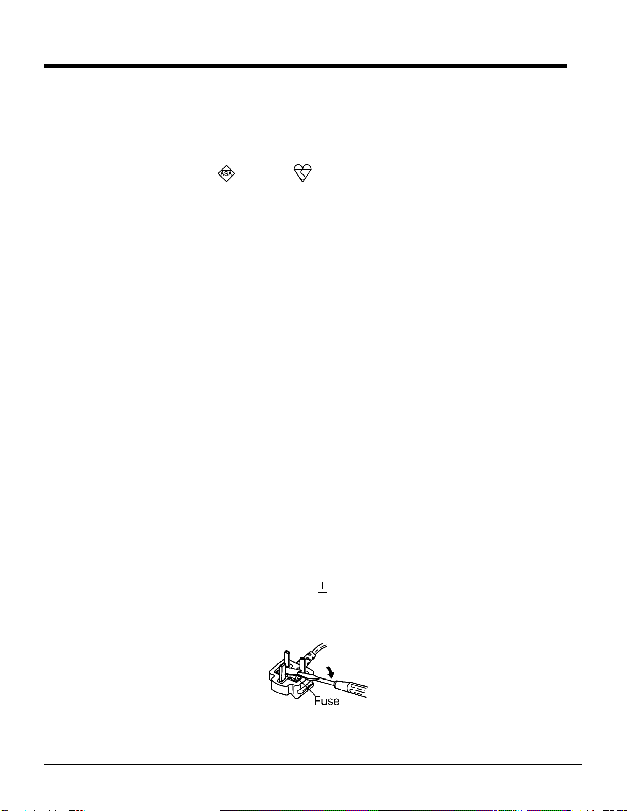
Do not defeat the safety purpose of the polarizedor
grounding-type plug. A polarized plug has two blades
with one wider than the other. A grounding type plug
has two blades and a third groundingprong. The
wider blade or third prong is provided for your safety.
If the provided plug does not fit into your outlet,
consult an electrician for replacement ofthe obsolete
outlet.
CAUTION
RISK OF ELECTRIC SHOCK
DO NOT OPEN
The lightning flash with arrowhead symbol within an
equilateral triangle, indicates that dangerous
voltage constituting a risk of electric shock is
present within this unit.
The exclamation point witnin on equilateral triangle,
indicates that there are important operating and
maintenance instructions in the literature accompa-
nying this unit.
CAUTION: TO REDUCE THE RISK OF ELECTRIC SHOCK, DO NOT
REMOVE COVER. NO USER SERVICABLE PARTS INSIDE. REFER
SERVICING TO QUALIFIED SERVICE PERSONNEL.
IMPORTANT SAFETY INSTRUCTIONS
Protect the power cord from being walked on or
pinched, particularly at plugs, convenience
receptacles, and the point where they exit from the
apparatus.
Only use attachments/accessories specified by
themanufacturer.
Unplug this apparatus during lightning storms, or
when unused for long periods of time.
Refer all servicing to qualified service personnel.
Servicing is required when the apparatus has
been damaged in any way, such as power-supply
cord or plug is damaged, liquid has been spilled or
objects have fallen into the apparatus, the
apparatus has been exposed to rain or moisture,
does not operate normally, or has been dropped.
Apparatus shall not be exposed to dripping or
splashing and no objects filled with liquids, such as
vases, shall be placed on the apparatus.
WARNING: To reduce the risk of fire or electric
shock, do not expose this apparatus to rain or
moisture.

3
Leslie 2121/2122/2123 Owner’s Manual
FOR UNITED KINGDOM:
FOR YOUR SAFETY, PLEASE READ THE FOLLOWING TEXT CAREFULLY
This appliance is supplied with a molded 3-pin mains plug for your safety and convenience.
A 5 amp fuse is fitted in this plug.
Should the fuse need to be replaced, please ensure that the replacement fuse has a rating of 5 amps
and that it is approved by ASTA or BSI to BSI1362.
Check for the ASTA mark or the BSI mark on the body of the fuse.
If the plug contains a removable fuse cover, you must ensure that it is refitted when the fuse is replaced.
If the fuse is lost, the plug must not be used until a replacement cover is obtained.
A replacement fuse cover can be obtained from your local Hammond Dealer.
IF THE FITTED MOULDED PLUG IS UNSUITABLE FOR THE SOCKET OUTLET IN YOUR HOME,
THEN THE FUSE SHOULD BE REMOVED AND THE PLUG CUT OFF AND DISPOSED OF
SAFELY.
THERE IS A DANGER OF SEVERE ELECTRICAL SHOCK IF THE CUT-OFF PLUG IS INSERTED
INTO ANY 13 AMP SOCKET.
If a new plug is to be fitted please observe the wiring code as shown below.
If in any doubt, please consult a qualified electrician.
IMPORTANT - The wires in this mains lead are coloured in accordance with the following code:
Blue: Neutral
Brown: Live
As the colours of the wires in the mains lead of this unit may not correspond with the coloured marking
identifying the terminals in your plug, proceed as follows.
The wire which is coloured BLUE must be connected to the terminal in the plug which is marked with
the letter N or coloured BLACK.
The wire which is coloured BROWN must be connected to the terminal in the plug which is marked with
the letter L or coloured RED.
Under no circumstances should either of these wires be connected to the earth terminal of the three-pin
plug, marked with the letter E or the Earth Symbol .
How to replace the fuse. Open the fuse compartment with a screwdriver and replace the fuse and fuse
cover.

4
Leslie 2121/2122/2123 Owner’s Manual
for your purchase of Leslie® Speaker System. Your new Leslie Speaker
culminates many years of reserch and dedication to the art of sound
reproduction. This new Leslie Speaker has been designed to provide the
utmost in musical enchantment, plus dependable service.
The Leslie Speaker system sets revolutionary new standards of organ
speaker performance, achieving heights of musical excellence never before
considered possible. Not just another speaker - it marks a major
breakthrough in organ sound, perhaps the most significant step forward
since the introduction of the electronic organ.
Many features have been included in the speaker to insure the finest organ
sound possible. Please take a moment to read this manual, then turn on
your new Leslie Speaker and enjoy your organ playing to the fullest.
thank
you...

5
Leslie 2121/2122/2123 Owner’s Manual
TABLE OF CONTENTS
IMPORTANT SAFETY INSTRUCTIONS..............................2
CONTROL PANEL AND FUNCTIONS................................6
BASIC HOOK-UP WITH #2101.........................................8
CONNECTING UNITS IN SERIES.....................................9
SPECIFICATIONS .........................................................10
SERVICE......................................................................11

6
Leslie 2121/2122/2123 Owner’s Manual
7
CONTROL PANEL AND FUNCTIONS
LINE
LINE LINE
POWER
ON
FROM
Leslie #2101/2102
ONLY
TW. LEVEL
MIC
GAIN
ON
OFF
(REMOTE)
OFF ON
(XLR ONLY)
TIP: RETURN
RING: SEND
INPUT 2
BASSVOLUME INSERT VOLUME VOLUME VOLUMETREBLE
PHANTOM
XLR: Lo-Z
PHONE: Hi-Z
INPUT 1
AC IN
INPUT 3 TONE MASTER
LINE OUT
-10-10 +10+10
-5+5
POWER
0 10 0 10 0 10 0 10
REMOTE
21
Stationary-Unit
PUSH
ON/OFF POWER SWITCH
Use this switch to turn the unit "ON" or "OFF." To turn the unit "ON," simply press this
switch in at the top. To turn the unit "OFF," press the switch at the bottom.
AC IN
Use this receptacle to connect the A.C. Power Cord provided with your unit. Locate the A.C.
Power Cord and plug the female end into the A.C. Power receptacle, and the male end into
your A.C. power outlet.
GAIN Switch
Use this switch to adjust the impedence of the signal coming in from the INPUT 1 jack. Use
the MIC position when conecting a microphone and the LINE position for connecting an
external sound device such as a keyboard, synthesizer, etc.
INPUT 1 Volume Control
This Rotary Control adjusts the level of the signal from the INPUT 1 jack.
PHANTOM Switch
If you are plugging an XLR-type plug into the INPUT 1 jack, set this switch to the "ON"
position in order to supply a 24-volt phantom power source required by an XLR plug. For all
other conections, set this switch to the "OFF" position.
INPUT 1 Jack
Use this jack to connect to an external sound device. The jack will accept either an XLR
(low-impedence) or a PHONE (1/4" high-impedence) connection.
INSERT Jack
Use this jack to connect a signal processor.
NOTE: Be sure to use a Stereo "Y" cable, as the #2121/2122/2123 uses the "ring" to SEND the
signal and the "tip" to RETURN the processed signal.
1
2
3
4
5
6
1
2
3
4
5 6
7 8
9
:
!
a#$
%
&
b
(

7
Leslie 2121/2122/2123 Owner’s Manual
INPUT 2 Volume Control
This Rotary Control adjusts the level of the signal from the INPUT 2 jack.
INPUT 2 Jack
Use this jack to connect to an external sound device. The jack will accept a PHONE (1/4"
high-impedence) connection only.
INPUT 3 Volume Control
This Rotary Control adjusts the level of the signal from the INPUT 3 jack.
INPUT 3 Jack
Use this jack to connect to an external sound device. The jack will accept a PHONE (1/4"
high-impedence) connection only.
TONE Controls
The Treble and Bass Tones can be controlled separately with the use of these two Rotary
Controls. Turn each control to the left (counter-clockwise) for the minimum amount of
Treble or Bass. Turn each control to the right (clockwise) for the maximum amount of
Treble or Bass.
MASTER VOLUME Control
This Rotary Control allows you to control the total or maximum volume of the entire unit.
Turning this control clockwise will increase the total volume, while turning it counter-
clockwise will decrease the total volume.
REMOTE
The Leslie #2121/2122/2123 can be powered "ON" from the Leslie #2101/2102/2103 Rotary
unit by connecting the Rotary Unit to this receptacle via the enclosed DCC-2 cable.
NOTE: The AC Power Switch must be in the "OFF" position when using this feature.
WARNING: This receptacle is intended ONLY for the Leslie 2101/2102/2103. Attempting to connect
other instruments may seriously damage the unit.
POWER ON Light
This LED lights when the power is "ON."
LINE OUT Jack
Use this jack to connect another speaker or amplifier. This jack carries the sum of all incom-
ing signals, and is NOT affected by the TONE Controls or the MASTER VOLUME Control.
TW. LEVEL Control
This Rotary Control allows you to "fine-tune" the Treble response of the unit. Turning this
control clockwise will increase the amount of Treble, while turning it counter-clockwise will
decrease the amount of Treble.
8
9
:
!
$
%
&
(
b
a#

8
Leslie 2121/2122/2123 Owner’s Manual
BASIC HOOK-UP WITH #2101
u
v
w
x
y
ON
POWER
ON
OFF
(REMOTE)
POWER
OFF
POWER
OFF ON
OFF
VOLUME
MASTER
0 10
POWER
ON
POWER
OFF ON
ON
ON
Make sure the power on the Leslie
Speakers as well as on the connecting
instrument(s) is "OFF."
Make the connection shown in the
figure at the left. Connect the
Rotary-Unit to the Stationary-Unit
using the DCC-2 Cable. Then
connect the sound source to the
LINE IN jacks as shown.
Finally, connect the Stationary-
Unit to AC power.
Set the controls similar to the
settings shown in the figure at the
left.
Turn on the sound source. The Leslie
Speakers will be powered up automati-
cally.
Turn the MASTER VOLUME Rotary
Control to the 3 o'clock position to check
the sound level, then adjust the sound
level to your liking.
connecting
Instrument(s)
Leslie #2101 and
#2121
connecting
Instrument(s)
Leslie #2101 and
#2121
LINE
LINE LINE
POWER
ON
FROM
Leslie #2101/2102
ONLY
TW. LEVEL
MIC
GAIN
OFF ON
(XLR ONLY)
TIP: RETURN
RING: SEND
INPUT 2
BASSVOLUME INSERT VOLUME VOLUME VOLUMETREBLE
PHANTOM XLR: Lo-Z
PHONE: Hi-Z
INPUT 1 INPUT 3 TONE MASTER
LINE OUT
-10-10 +10+10
-5+5
010 010 010 010
REMOTE
PUSH
DCC-2
LI-40
Leslie #2101
ROT
BASS
LEV
0 10
Rise Time
Fast Speed
Slow Speed [Control Ch]
[Prog. Ch]
[Mod Rx]
[Exp Rx]
[S/F Type]
[P.F.SW Type]
[DumpOut]
[S/F Cont.Code]
Cross Over Freq./ Cabi. Resonance
Fall Time
Brake Time
Rotor Direction /Mic Angle
Character /Mic Distance
FUNCTION
DOWN UP
VALUE
ROTARY
POWER
ON
AC IN
OFF
(REMOTE)
STATIONARY
L R
OVER DRIVE
STA
MONO
BASS
& STA
MUTE
NORMAL
MEMORY
L/MONO R L/MONO R
STATIONARY
& ROT. BASS
ROTARY ROTARY
LESLIE
8PIN
LESLIE
11PIN
REMOTE
to Leslie 2121
MIDI IN
MIDI OUT
LINE OUT LINE IN FOOT SW
HORN
ROTOR
LOW
ROTOR
PRESET
12
FUNCTION
SELECT
Touch & Hold
[MIDI]
PRESET
SELECT
21
SLOW / FAST
STOP
PRESET
Rotary-Unit
Horn
HORN
LEVEL
VOLUME
21
0 10 0 10 0 10

9
Leslie 2121/2122/2123 Owner’s Manual
CONNECTING UNITS IN SERIES
LINE
LINE LINE
POWER
ON
FROM
Leslie #2101/2102
ONLY
TW. LEVEL
MIC
GAIN
OFF ON
(XLR ONLY)
TIP: RETURN
RING: SEND
INPUT 2
BASSVOLUME INSERT VOLUME VOLUME VOLUMETREBLE
PHANTOM
XLR: Lo-Z
PHONE: Hi-Z
INPUT 1 INPUT 3 TONE MASTER
LINE OUT
-10-10 +10+10
-5+5
010 010 010 010
REMOTE
PUSH
LINE
LINE LINE
POWER
ON
FROM
Leslie #2101/2102
ONLY
TW. LEVEL
MIC
GAIN
OFF ON
(XLR ONLY)
TIP: RETURN
RING: SEND
INPUT 2
BASSVOLUME INSERT VOLUME VOLUME VOLUMETREBLE
PHANTOM
XLR: Lo-Z
PHONE: Hi-Z
INPUT 1 INPUT 3 TONE MASTER
LINE OUT
-10-10 +10+10
-5+5
010 010 010 010
REMOTE
PUSH
Using Additional Stationary-Units for Maximum Sound Coverage.
Connect additional Stationary-Units using the INPUT 2 jacks as shown below.
To insure uniform quality of sound, set the INPUT 2 Rotary Controls on all the units
to the center (12 o'clock) position.
Master Unit Additional Unit
NOTE:
Only one Stationary-Unit can be connected using a DCC-2 cable.
Additional Stationary-Units must be powered "ON" and "OFF" separately.
NOTE:
When using additional #2121/2122/2123 Stationary-Units the MASTER VOLUME and
TONE controls of the additional units will NOT affect the sound. Use the MASTER
VOLUME and TONE controls of the Master Unit to set the sound quality that you prefer.

10
Leslie 2121/2122/2123 Owner’s Manual
SPECIFICATIONS
SPECIAL NOTE:
To prevent damage from excessive heat, the #2121/2122/2123 Stationary-Unit has a
thermal-protection circuit which will temporarily turn the audio "OFF" to allow the circuits to
cool. If this happens, do not turn the power "OFF". The audio circuit will automatically be
enabled when the temperature returns to a safe level.
Type
Powered Speaker, 2-way, Bass-reflex
Speaker Units LF: 38cm Cone
HF: Compression driver
Frequency Range
40Hz - 15kHz
Maximum SPL
121dB SPL (1m)
Dimension
506 x 763 x 506mm
Weight
39kg
Color
Black(#2121), Silver(#2122), Walnut(#2123)
Accessories
AC-Cord, LI-40 Cable x 2, DCC-2 Cable
Amplifier Output LF: 150W at 400Hz
HF: 50W at 1000Hz
Crossover Frequency
700Hz
Controls INPUT 1: PHANTOM, GAIN, VOLUME
INPUT 2: VOLUME
INPUT 3: VOLUME
TONE: BASS, TREBLE
MASTER: VOLUME
TW.LEVEL
POWER ON/OFF
Terminals INPUT 1: XLR/PHONE -20dB(LINE), -40dB(MIC)
600 ohm(XLR), 50kohm(PHONE)
INPUT 2: PHONE -15dB, 10kohm
INPUT 3: PHONE -15dB, 10kohm
SEND: PHONE -6dB, 600ohm
RETURN: PHONE -6dB, 50kohm
LINE OUT: PHONE 0dB, 1kohm
(0dB=0.775V)
REMOTE: ONLY FROM #2101/2102/2103
AC IN
Indicator
POWER ON
Power Displayed on name plate at rear panel

11
Leslie 2121/2122/2123 Owner’s Manual
SERVICE
Hammond maintains a policy of continuously improving and upgrading its instruments and therefore reserves
the right to change specifications without notice. Although every attempt has been made to insure the accuracy
of the descriptive contents of this Manual, total accuracy cannot be guaranteed.
Should the owner require further assistance, inquiries should first be made to your Authorized Hammond
Dealer. If you still need further assistance, contact Hammond at the following addresses:
In the United States Contact:
HAMMOND SUZUKI USA, Inc.
733 Annoreno Dr.
Addison, IL 60101
UNITED STATES
In Europe contact:
HAMMOND SUZUKI EUROPE
B.V.
IR. D.S. Tuynmanweg 4A
4131 PN Vianen
THE NETHERLANDS
All other countries contact:
HAMMOND SUZUKI Ltd.
25-11, Ryoke 2 Chome
Hamamatsu 430-0852
(Shizuoka)
JAPAN
E-mail: [email protected]
Website: www.hammondsuzuki.com
Technical materials are available and can be obtained by mailing a request to the appropriate address listed above
marked ATTENTION: SERVICE DEPARTMENT.
Manufacturer:
SUZUKI MUSICAL INSTRUMENT MFG. CO., Ltd.
25-12, Ryoke 2 Chome
Hamamatsu 430-0852 (Shizuoka)
JAPAN

HAMMOND SUZUKI, LTD., Hamamatsu, Japan Printed in Japan
00457-40068
V1.1-0205
This manual suits for next models
2
Table of contents
Other Leslie Speakers System manuals