--~
~---~
~~-.~---
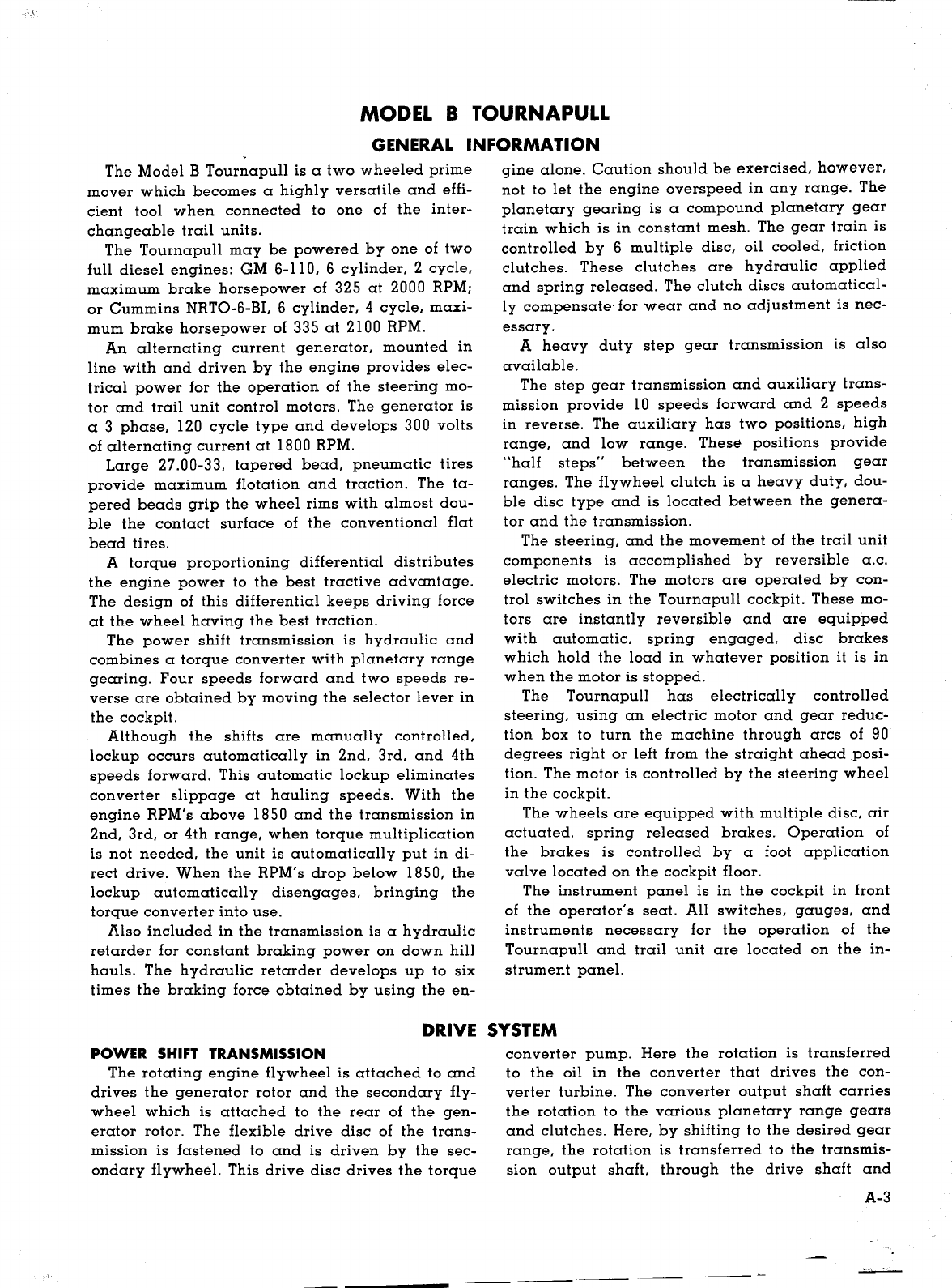
pUO Hoqs aAllP aqJ qfino.IqJ 'Hoqs mdmo trots
-srmsun.n
aqJ OJ pa.I.IaJsuo.IJ s1 uOHoJ0.I aqJ 'afiuo.I
.lOafi pa.I1sap aqJ OJ fiunnqs Aq 'a.IaH "saq::>Jnp puo
s.Ioafi efnmr A.I0Jauold Sn01l0A aqJ OJ uOHoJ0.I aqJ
satrrno Hoqs mdmo .IapaAUO::>aqJ. "au1q.InJ .IapaA
-uoo aqJ SaApP loql .IapaAUO::> aql U1 HO aql 0l
pa.I.IaJsuo.Il S1 UOHOl0.I aql a.IaH
-dnmd
.IapaAUO::>
anbro; aqJ SaA1.IP ::>S1PaAPP s1qJ. "laaq.M.Au A.lOPUO
-::>as aql Aq UaAPP S1 pUO o; paUalsoJ S1
uotssrm
-SUO.IJ aqJ JO ::>S1PaAFP alq1xau aqJ. ".I0l0.I .I0lo.Ia
-uafi aqJ JO .Ioa.I aql OJ paq::>ouo s1 q::>1q.M.laaq.M.
-AU A.lOpuo::>as aql puo .I0l0.I .IOl0.Iauafi aql saAFP
puo o; paq::>ouo s1 laaq.M.AIJ aU1fiua fiUHOl0.I aqJ.
NOISSIWSNVBl 1:IIHS 1I3MOd
W31SA.S 3AIliO
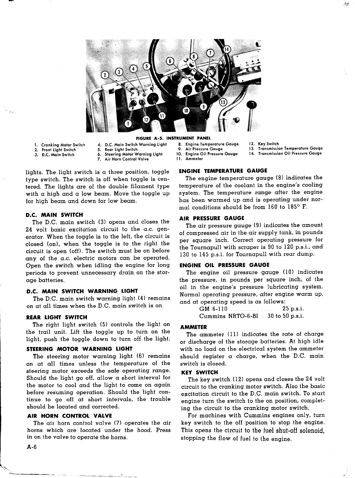
"lauod nreum.ns
-u] aqJ uo paJ0::>0l a.IO Hun HO.IJ puo nndoum0J.
aql JO UOH0.Iado aqJ .I0J A.IOSsa::>au sJuamn.IJsu1
puo 'safinofi 'saq::>H.M.s 1I'sf "loas S,.I0l0.Iado aql JO
JUO.IJU1 Hd:po::> aql U1 S1 lauod lUamn.IlSU1 aqJ.
".IooIJ Hd:po::> aql uo paJ0::>0l aAloA
UOH0::>nddo lOOJ 0 Aq pan0.IJuo::> s1 sa:l"[o.Iq aqJ
JO UOHD.IadO "sa:l"[o.Iq pasoala.I fiuFds 'palonpo
.110'::>s1Paldmnm qH.M.padd1nba a.lO slaaq.M. aqJ.
"Hd:l"[::>o::>aql u1
laaq.M. fiupaals aqJ Aq pan0.IJuo::> s1 .I0Jom aqJ. oucH
-1sod poaqo Jqfi10.IlS aqJ mO.IJ Hal .10 lqfi1.I saa.Ifiap
06 JO S::>.IOqfino.Iql aU1q::>om aql uml 0l xoq uOH
-:mpa.I .Ioafi pUO .I0lom ::>1.Ipala uo fiu1sn 'fiuFaals
pan0.IJuo::> AlIo::>Fl::>ala soq llndoum0J. aqJ.
"paddolS S1.I0lom aql uaq.M.
U1 S! H uomsod .IaAaJoq.M. U! POOl aqJ Ploq q::>!q.M.
sa}'[o.Iq ::>S!P 'pafiofiua fiUFds '::>HomoJno qH.M.
padd!nba a.IO puo alq!s.IaAa.I AHuoJsU! a.lO S.I0J
-om asaqJ. "nd}'[::>o::>llndou.In0J. aql U! saq::>H.M.sl0.IJ
-uo::> Aq paJ0.Iado a.IO S.I0Jom aqJ. "S.I0lom ::>Fpala
"::>"0alq!s.IaAa.I Aq paqsndmo::>::>o S! sluauodmo::>
Hun HO.IJaqJ JO JuamaAom aqJ puo 'fiuFaaJs aqJ.
"u01ss1msuo.IJ aql puo .I0l
-o.Iauafi aqJ uaa.M.laq pal0::>0l S! puo adAJ ::>s1Palq
-nop 'Alnp AAoaq 0 S! q::>lnp laaq.M.AIJ aqJ. "safiuD.I
.Ioafi UO!SS1msuo.IJ aql Uaa.M.laq "sdaJs Hoq"
ap1AO.Id suomsod asaqJ. "afiuo.I .M.0l puo 'afiuo.I
qfi!q 'suomsod O.M.Jsoq A.I0H!xno aqJ. "as.IaAa.I U!
spaads
Z
puo P.IO.M..I0Jspaads 01 ap!Ao.Id uo!ss!m
-SUO.Il A.lO!Hxno puo uo!ss!msuD.IJ .Ioafi daJs aqJ.
"alqoHoAo
oSlo S1 uo!ss!mSUO.Il .lOafi daJs Alnp AAoaq 'sf
"A.IOSSa
-::>au S! luamlsn[po ou puo .Ioa.M..I0J"alosuadmo::> Al
-l0::>Homolno s::>s1Pq::>lnp aqJ. "pasoala.I fiUFds puo
panddo ::>nnO.IpAq a.lO saq::>lnp asaqJ. "Saq::>lnp
uOH::>FJ 'palco::> HO '::>s1Paldmnm 9 Aq pall0.Iluo::>
S! U10.IJ .Ioafi aqJ. "qsam JUDIsuo::> u1 S! q::>!q.M.U10.Il
.Ioafi A.I0lauold punodmo::> 0 s1 fiuFoafi A.lOlauold
aqJ. "afiuD.I AUO U! paadS.IaAO aU1fiua aqJ Jal 0l IOU
'.IaAa.M.oq 'pasp.Iaxa aq Plnoqs uOHno:::> "auolO au!fi
-ua aqJ fitrtsn Aq pau!oJqo a::>.I0JfiUH0.Iq aql setm;
X!S oi dn sdolaAap .Iap.IoJa.I ::>nnO.IpAq aqJ. "slnoq
mq U.M.0Puo .Ia.M.od fiu!}'[o.Iq nmisuoo .I0J .Iap.lOla.I
::>nnO.IpAq 0 S! uo!ss!msuo.Il aql u1 papnpu1 oSl'sf
"asn OlU! .IapaAuo::> anb.I0l
aql fiU1fiuFq 'safiofiuas1P AlI0::>Homolno dn}'[::>0l
aqJ '0~8
I
.M.0laq do.Ip s,WdH aqJ uaqM "aAFP l::>a.I
-!P U1 lnd AlI0::>Homolno S! Hun aql 'papaau IOU s1
UOH0::>ndmnm anb.I0l uaq.M. 'afiuo.I qlv .10 'P.I8 'puZ
U! uo!ss!msUo.Il aql puo 0~8
I
aAoqo s,WdH au!fiua
aql qnM "spaads fiunnoq JO afioddns .IapaAuo::>
saJou!mna dn}'[::>0l::>HomoJno s1qJ. "P.lO.M..I0Jspaads
qJv puo 'P.I8 'puZ U! AlI0::>HomoJno sm::>::>odn}'[::>0l
'palI0.IlUO::> Allonuom a.lO smqs aql qfinoqH'sf
"nd}'[::>o::>aql
U! .IaAal .I0J::>alas aqJ fiU!AOm Aq pau101qo a.IO as.IaA
-a.I spaads O.M.lpuo P.IO.M..I0Jspaads .Ino.:{ "fiuFOafi
afiuo.I A.I0JauDld qH.M..IapaAuo::> anb.I0J 0 sauNmo::>
puo ::>nnO.IpAq S! u01ss!mSUO.Il mqs .Ia.M.od aqJ.
"uoH::>O.Illsaq aql fiU!AOq laaq.M. aqJ JO
a::>.I0JfiU!AFP sdaa}'[ 10Hua.Iamp S!ql JO ufi!sap aqJ.
"afiOlUOAPO aA!po.Il Jsaq aql 0l .Ia.M.od aU1fiua aqJ
saJnqFlS!p 10Hua.Iamp fiu!uo!podo.Id anb.IOl 'sf
"sa.IH poaq
JOIJ 10uonuaAuo::> aql JO a::>oJ.Ins J::>0luo::>aqJ alq
-nop lsomlo qH.M.sm1.I laaq.M. aqJ dpfi spoaq pa.Iad
-OJ aqJ. "uoH::>O.Ilpuo uOHOlOIJ mnm1xom ap!Ao.Id
sa.IH ::>Homnaud 'poaq pa.IadoJ
'88-00"a
afi.I0
1
"WdH 0081 lO Jua.I.In::>fiuHOU.IaHo JO
SHOA 008 sdolaAap pUO adAl apA::>
OZI
'asoqd 8 0
S! .I0J0.Iauafi aqJ. "S.I0lom l0.IlUO::>Hun HO.Il puo .I0l
-om fiu!.IaalS aql JO UOH0.Iado aqJ .I0J .Ia.M.od IO::>1.IJ
-::>ala sap!Ao.Id au!fiua aqJ Aq uaAFP puo qH.M.aun
U! palunom '.IOl0.Iauafi Jua.I.In::> fiUHou.IaHo u'sf
"WdH
001Z
10 ~88 JO .Ia.M.odas.IOq a:l[D.Iq mnm
-1xom 'apA::>
V
'.IapUnA::> 9 'Ia-9-OJ.HN su!mmn:::> .10
!WdH
OOOZ
lO
~Z8
JO .Ia.M.odas.Ioq a:l[o.Iq mnm!xom
'apA::>
Z
'.IapUnA::> 9 'OII-9 WD :sau1fiua lasa!p lInJ
O.M.lJO auo Aq pa.Ia.M.od aq ADm lIndoum0J. aqJ.
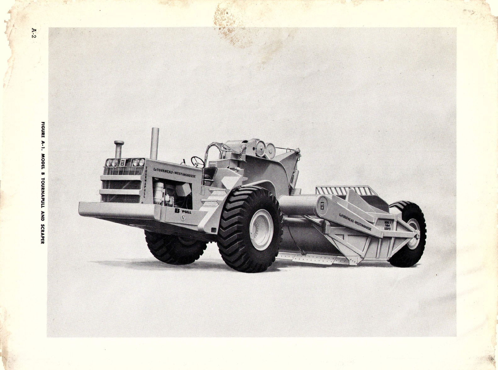
"sHun HO.Il alqoafiuoq::>
-.IalU! aql JO auo 01 papauuo::> uaq.M. 1001 Juap
-ma puo alHDS.IaA Alqfi1q 0 samo::>aq q::>!q.M..IaAOm
am!.Id palaaq.M. O.M.l0 S! lIndoum0J.
s:
lapow aqJ.
NOIlYWlIO:lNI lY1I3N39
llndVNlInOl 8 1300W