Letron Auto Gates SL600 Guide

LETRON AUTO GATES
AUSTRALIA PTY LTO
SERS
INSTALLATION
MANUAL
~_ ~~do=~~
>:~.~'"
cY~.;;-~~.,L~. /
_h.,-, ~ ~~_
~ S~L600-1DC Sliding Ga-te Opener ~~
Solar Compatible

IMPORTANT SAFETY WARNINGS-
Please read these important safety
warnings before installing or using this
product
•Never let children operate or play with the controls.
•Keep the remoter control away from the children.
•Do not operate the sliding gate unless the gate is in full view and free from
objects such as cars, children or people.
•Always keep the moving gate insight and away from any objects untii it's
completely opened/closed.
•Do not disengage the slider gate motor to manual operation with anyone
or any other objects, including motor vehicles, within the doorway.
•The slidergate must bewell balanced. Sticking or binding gates can
falsely trigger the obstruction sensing of the unit.
•Allmaintenance should be carried out by qualified personnel.
•Hegularly test the slidergate motor to ensure that the obstruction sensor
unit is operating properly.
• The slidergate motor has an electronic obstruction system that provides
safe and reliable operation. It's however a legal requirement in some
countries to also install a photo-electric sensor across the door way,
pleasecheck this requirement with your local distributor. However,it's
recommended to install this photo-electric sensor for all units.

Features
Your automatic Slider Gate Motor has
many features which you willappreciate.
The components and materials used in its
control board are of the latest technology
and highest quality.
The motor is used to drive a sliding gate,
with the moving speed of 12 meters per
minute. This gate-operator is powered by
AC220V,50Hz. It is featured with powerful
starting strength, capable of overload at
short time.When it's overloaded,it's
protected electrically and mechanically.
In case of power failure, a key can be used
to release the motor and move the gates
manually. Following lists some of its key
features.
OPERATION
To operate the slider door simply press the
remote control handset or the wall mounted
switch fortwo seconds and the door will
automatically open/close.
The gate can be stopped during on
opening or closing cycle by pressing the
remote control handset or wall switch. The
next actuation will move the gate in the
opposite direction.
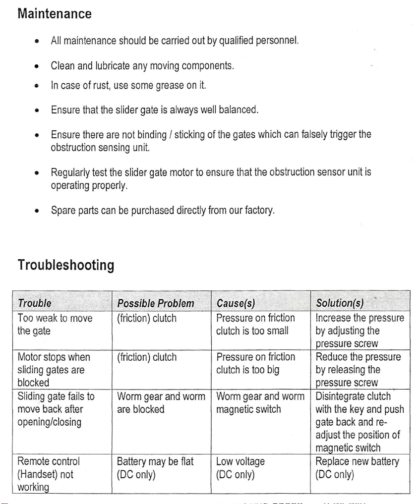
SAFETY OBSTRUCTION REVERSE
While the gate is performing closing cycle
and it should hit an obstacle orbe
restricted in some manner,it will
automatically reverse.
The amount of force the gate should
encounter before reversing is adjustable.
The gate will automatically stop if restricted
whilst opening.The Safety Obstruction
Forces should be checked at least once a
month.
SECURITY CODE STORE
The Sliding Gate Motor uses'state of the
Microchip®technology in storing your
Slider Code Transmitter Security Code.
Up to 20 different transmitters can be
stored in the non-volatile memory device.
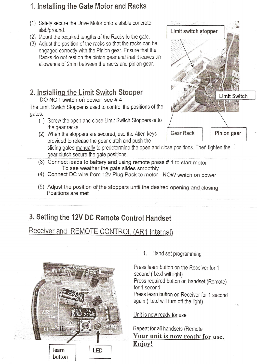
To store any code simply press the LEARN
button on the motor and press the
transmitterbutton twice.The codes can be
deleted at any time.
Security is enhanced because the fixed
and encrypted sections combined increase
the number of combinations to 7.38 x 10
9.
There is no Dip switch on themotor which
can be visually seen and copied.
OPEN AND CLOSE DRiVE BUTTON
Another feature developed to aidin the -
installation of the Slider Gate Motor is the
OISIC
Button. This button is used to help
set the open and close limit positions.A
quicker time setting and a more precise
limit position can be achieved using this
system.
AUTO CLOSE MODE
The Slider Gate Motor can be programmed
to automatically close at a selected period
(eg. thirty seconds) after the door has
opened.
A photo-electric beam must
be
installed if this mode is selected.
PHOTO ELECTRIC BEAM
The Sliding Gate Motor has an input for a
Photo-Electric Beam to be connected for
extra safety protection.
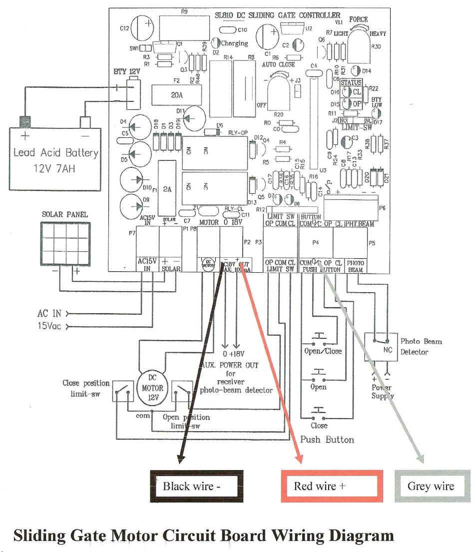
SOLAR COMPATIBLE
This device is able to use 12V DC, 24V DC
or 12V solar panel to operate.
POWER FAILURE
Gates can be moved manually by
Inserting key and Allen key into motor

1.Installing the Gate Motor and Racks
(1) Safely secure the Drive Motor onto a stable concrete
slab/ground.
(2) Mount therequiredlengths of the Racksto the gate.
(3) Adjust the positionof the racks so that theracks can be
engaged correctly withthe Pinion gear. Ensure thatthe
Racksdonotrestonthe pinion gear and that
it
leaves
an
allowance of 2mm betweenthe racks and piniongear.
"
.
"r~
2.1nstaliingJh~_ljmtt Switch Stonper
DO NOT switch onpower see
#
4
The Limit Switch Stopper is used to control the positions of the
gates,
(1) Screw the open and close Limit Switch Stoppers onto
the gear racks.
(2) When the stoppers are secured, use theAllen keys
providedto release the gear clutch andpush the
sliding gates manually to predetermine the openandclose positions. Then tightenthe -'
gear clutch securethe gate positions.
..
--------
(3) Connectleads to battery and using remote press
#
1to startmotor
To see weatherthe gate slides smoothly
(4)Connect DC wirefrom 12v Plug Pack to motorNOW switch on power
(5) Adjusttheposition ofthe stoppers untilthedesiredopening andclosing
Positions aremet
3.
Setting the12V
DC
Remote Control Handset
Receiver and REMOTE CONTROL fAR1 Internal)
learn
button
Press learn button on the Receiver for1
second ( .e.d will light)
Press required button on handset (Remote)
for 1 second
Press learn button on Receiver for1 second
again (.e.d willturn off the light)
Repeat for allhandsets (Remote
Your unit is now ready for use.
Enjoy

Sliding GateMotor - User s InstallationManual
3.Sensitivity Adjustment (R20)
1. Turn theOverload Sensor clockwise (toward light) to decreasesensitivity or anti-
clockwise (toward heavy) to increase sensitivity.
Note:
Many factorswill affect wherethis settingthat including gateweight,incline,
prevailing wing conditions and desired auto reverse load .The gate may not open or close
fully if the "Overload Sensor' is to its maximum 'Light' position. Conversely, thegatemay
not quickly auto reverse if the "OverloadSensor'is setto its maximum "Heavy'position.
4. Install Photoelectric Beams(Optional)
1 REMOVE the link wire from Com & PB ..
2 Powershould then be drawn via the 12VDC
3 TheTriggerwires should be connected to Com & PB.
5. Setting the 12V DCRemote Control Handset (GE-RCV1)
2.Connect cable as follows:
RED WiRE
BLACK
YELLOWOR BLUE
12V DC
+
OV DC - (Ground)
TRIGGER - (momentary
n/o
3. Hand set programming
- Press the'Learn'button on the receiver device for 1second (L.E.D will light up).
- Press the any button on the handset for 1 second.
- Press the same button on the handset again to confirm the setting,the L.E.D on
the receiver will flash approx. 10 secondsat whichtime the unit is then readyfor
use.
Repeat above steps forall handsets available.
Vour unit is now ready for use. Enjoy
Letron Auto Gate (Australia) Pty. Ltd.

Lead Acid Battery
12V 7AH
AC IN
15Vac
Close position
limit-sw
(])
CJ
I1;l
SLaW
IX; SLIDING GATE CONTROLLE~IFORCE
CI2
+'
'--"CIO ~F==JU2~
'------J
V
L-J
R7UGHT HEAVY
mY 12V
Q3
0
c=>
Oli O'
D14
F2
&f~
II-
+J3 c6§fATUS
I
20AI
B
D'6~cdl~
_.__.---.--J
Off DI'
r
OP
l,J
LOW
~\ R20 Rll
{=:=J-,.
D1n~_",~ RO
B
J2NO,NCD17
2PMa~~~
~'~lo,)'~
~.;~~wOO'
c;~
R
R5~-eJ-G~
u3()~o:m~rr3'"aD
~J~
"f"tD
R16
2
N
DIO
n
2A
15?i
u')<'
u
r
In;,:~
0
0
G09 Q5
DYtlirl
~U()
013
VVoa
--.----J,IC-l
IJ.~Y-CL
RI2cr:·-~
ACl5V .
L.....J-'
~Cll LIMIT
SW-BuTI'tlN
IN
fL'':.
C7 MOTOR 0 18Y OP COMCL COM 0 C
PI P8 -
r
Black wire ~
I
Red wire
+
Sliding
G~te
Mptor(::ircuit
~oard
Wiring Diagram

Package List
1
1
1
2
2
2
2
1
4metres
Optional (recommended
Technical Specifications
Input Power 240V
Power Supply 15V AC Transformer 12V DC OrSolar
Starting Current <4A
t>-.
Duty Cycle 50%
Gate Moving Speed 12M/ Min
Gate Length To Spec
Gate Weight 600 Kg

• Clean and lubricate any moving components.
•In case ofrust,use somegrease on it.
• Ensure there are not binding /sticking of the gates which can falsely trigger the
obstruction sensing unit.
• Regularly test the slider gate motor to ensure that the obstruction sensor unit is
operating properly.
Troubleshooting
·T;o~bjej·
"
;-_
...
,
..
;
Too weak to move
the gate
Motor stops when
sliding gates are
blocked
Sliding gate fails to
move back after
opening/closing
Remote control
(Handset)not
workin
Pos ible;PrOblem
(friction) clutch
,Causers)
Pressureon friction
clutch is too small
Pressure on friction
clutch is too big
Worm gear and worm Worm gearand worm
are blocked magnetic switch
Battery may be flat
(DC only) Low voltage
(DC only)
Solution ;)/
Increase the pressure
by adjusting the
pressure screw
Reduce the pressure
by releasing the
pressure screw
Disintegrate clutch
with the key and push
gate back and re-
adjust the positionof
ma netic switch
Replace new battery
(DC only)
Table of contents
Popular Gate Opener manuals by other brands

Eagle Access Control Systems
Eagle Access Control Systems 1000 series owner's manual

Matikgate
Matikgate RAM Installer manual

BFT
BFT PHOBOS N installation manual

Nice
Nice RUN1800 Instructions and warnings for the fitter

Chamberlain
Chamberlain MIRACLE-ONE owner's manual

Viking Access Systems
Viking Access Systems K-2S Installation instructions and safety information

Motorline
Motorline MC410 installer and user manual

SOMFY
SOMFY HOME MOTION Axovia 220B installation instructions

Motorline professional
Motorline professional PERGOLA installer and user manual

BFT
BFT ARES Installation and user manual

Erreka
Erreka ARC Series Installer manual

AGA
AGA GATEMASTER 900 HD installation manual