LeuchtKraft PARC-150/EFF User manual

LEUCHTKRAFT
BEDIENUNGSANLEITUNG
INSTRUCTION MANUAL
LED-Spot-Scheinwerfer
mit Stroboskop-Effektring
LED Spotlight
with Strobe Effect Ring
PARC-150/EFF
Bestell-Nr. • Order No. 38.8440


3
Deutsch ..........Seite 4
English ...........Page 12

4
Deutsch
English
English Page
Français
Français Page
Italiano
Italiano Pagina
Español
Español Página
Nederlands
Nederlands Pagina
Polski
Polski Strona
Deutsch
Deutsch Seite
LED-Spot-Scheinwerfer mit
Stroboskop-Effektring
Diese Anleitung richtet sich an den Installateur
des Geräts und an den Bediener mit Grund-
kenntnissen in der DMX-Steuerung. Bitte lesen
Sie die Anleitung vor dem Betrieb gründlich
durch und heben Sie sie für ein späteres Nach-
lesen auf.
1 Einsatzmöglichkeiten
Dieser Scheinwerfer dient zur Effektbeleuchtung
z.B. auf Bühnen, in Diskotheken und Festsälen.
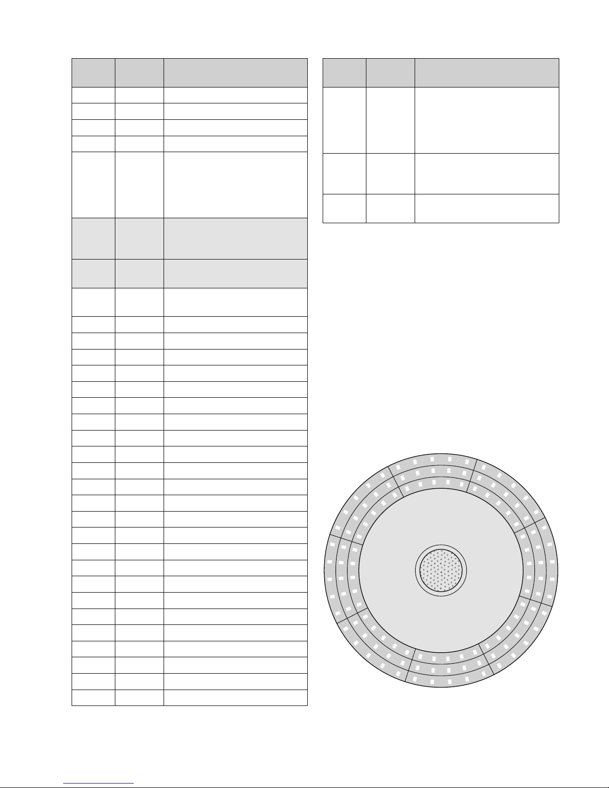
Als Lichtquelle ist eine leistungsstarke COB-LED
eingesetzt (COB = Chip-on-Board-Technologie):
Viele einzelne LEDs sind eng zusammen auf
einem Chip untergebracht. Dadurch wird eine
gleichmäßige Lichtverteilung erreicht.
Zusätzlich ist der PARC-150/EFF mit einem
Stroboskop-Effektring ausgestattet, der aus 120
kleinen, weißen LEDs besteht.
Der Scheinwerfer ist für die Steuerung über
ein DMX-Lichtsteuergerät ausgelegt (7, 11 oder
35 DMX-Steuerkanäle wählbar). Er kann aber
auch allein betrieben werden oder im Verbund
mit mehreren PARC-150/EFF im Master-Slave-
Modus. Zusätzlich sorgt das integrierte Mikrofon
für musiksynchrone Effekte.
2 Sicherheitshinweise
Das Gerät entspricht allen relevanten Richtlinien
der EU und trägt deshalb das -Zeichen.
WARNUNG
Das Gerät wird mit lebensge-
fährlicher Netzspannung ver-
sorgt. Nehmen Sie deshalb nie
selbst Eingriffe am Gerät vor. Es
besteht die Gefahr eines elektri-
schen Schlages.
•
Verwenden Sie das Gerät nur im Innenbereich
und schützen Sie es vor Tropf- und Spritzwas-
ser sowie vor hoher Luftfeuchtigkeit. Der
zulässige Einsatztemperaturbereich beträgt
0–40°C.
•
Ziehen Sie sofort den Netzstecker aus der
Steckdose,
1.
wenn sichtbare Schäden am Gerät oder
am Netzkabel vorhanden sind,
2.
wenn nach einem Sturz oder Ähnlichem
der Verdacht auf einen Defekt besteht,
3. wenn Funktionsstörungen auftreten.
Geben Sie das Gerät in jedem Fall zur Repa-
ratur in eine Fachwerkstatt.
•
Ziehen Sie den Netzstecker nie am Kabel aus
der Steckdose, fassen Sie immer am Stecker
an.
•
Wird das Gerät zweckentfremdet, nicht fach-
gerecht montiert, falsch bedient oder nicht
fachgerecht repariert, kann keine Haftung
für daraus resultierende Sach- oder Perso-
nenschäden und keine Garantie für das Gerät
übernommen werden.
Soll das Gerät endgültig aus dem Be-
trieb genommen werden, übergeben
Sie es zur umweltgerechten Entsor-
gung einem örtlichen Recyclingbetrieb.
3 Inbetriebnahme
3.1 Montage
•
Platzieren Sie das Gerät immer so, dass im
Betrieb eine ausreichende Luftzirkulation ge-
währleistet ist. Die Lüftungsöffnungen am
Gehäuse dürfen auf keinen Fall abgedeckt
werden.
•
Der Abstand zum angestrahlten Objekt sollte
mindestens 50cm betragen.
WARNUNG
Der Scheinwerfer muss fachge-
recht und sicher montiert wer-
den. Wird er an einer Stelle in-
stalliert, unter der sich Personen
aufhalten können, muss er zusätzlich gesichert
werden (z.B. durch ein Fangseil am Montage-
bügel; das Fangseil so befestigen, dass der
Fallweg des Gerätes nicht mehr als 20cm be-
tragen kann).
1.
Den Scheinwerfer über die Montagebügel
befestigen, z.B. mit einer Befestigungsschelle
(TA-100, TA-110) an einer Traverse.
Zum Ausrichten des Scheinwerfers die
zwei Feststellschrauben der Montagebügel
lösen. Die gewünschte Neigung des Schein-
werfers einstellen und die Schrauben wieder
festziehen.

5
Deutsch
2.
Alternativ lässt sich der Scheinwerfer auch
frei aufstellen: Die Montagebügel so unter
dem Scheinwerfer spreizen, dass sie als Stän-
der dienen. Die Feststellschrauben danach
festdrehen.
3.2 Netzanschluss
Wichtig! Zur Stromversorgung ist das Gerät mit
Powercon-Anschlüssen ausgestattet. Ein Power-
con-Stecker darf nicht unter Spannung ein- oder
ausgesteckt werden. Stellen Sie darum immer
zuerst die Powercon-Verbindung am Gerät her,
bevor Sie den Netzstecker in eine Steckdose
stecken. Nach dem Betrieb ziehen Sie zuerst
den Netzstecker aus der Steckdose, bevor Sie
den Powercon-Stecker aus dem Gerät ziehen.
1)
Das Gerät über die blaue Netzbuchse POWER
IN mit dem beiliegenden Netzkabel an eine
Steckdose (230 V/50 Hz) anschließen. Den
blauen Powercon-Stecker des Netzkabels
nach dem Einstecken in die Netzbuchse nach
rechts drehen, bis er einrastet. Zum späte-
ren Herausziehen den Sicherungsriegel am
Stecker zurückziehen und den Stecker nach
links drehen.
2) Werden mehrere PARC-150/EFF verwendet,
kann die weiße Buchse POWER OUT des ers-
ten Geräts mit der Netzbuchse POWER IN des
zweiten Gerätes verbunden werden. Dazu
wird ein Netzkabel mit Powercon-Steckern
(NAC-3FCB und NAC-3FCA) benötigt. Das
zweite Gerät kann dann wieder mit dem drit-
ten Gerät verbunden werden usw., bis alle
Geräte in einer Kette angeschlossen sind. Auf
diese Weise lassen sich maximal 16 Geräte
zusammenschalten.
3)
Die Buchse POWER OUT kann auch zur
Stromversorgung anderer (Lichteffekt-)Ge-
räte genutzt werden. Jedoch dürfen die
Buchsen POWER IN und POWER OUT nicht
mit einem Strom von mehr als 16A belastet
werden. Es kann sonst durch die Überlastung
ein Kurzschluss und Brand entstehen.
4 Bedienung
Sobald der Scheinwerfer mit dem 230-V-Netz
verbunden ist, ist er dadurch auch eingeschal-
tet. Zur Betriebsanzeige leuchtet ein Punkt im
Display. Liegt ein DMX-Signal am DMX-Eingang
an, blinkt der Punkt.
WARNUNG
Blicken Sie nicht für längere Zeit
direkt in die Lichtquelle, das kann
zu Augenschäden führen.
Beachten Sie, dass sehr schnelle Lichtwechsel
bei fotosensiblen Menschen und Epileptikern
epileptische Anfälle auslösen können!
Das Gerät kann auf 3 verschiedene Arten ar-
beiten:
1. eigenständiger Betrieb mit Farbwechsel
2. musikgesteuert über das eingebaute Mik-
rofon
3. DMX-gesteuert über ein Lichtsteuergerät (z.B.
DMX-1440 oder DMX-510USB)
Die Wahl des Betriebsmodus und das Ändern
von Einstellungen erfolgt über ein Menü mit den
Bedientasten. Wird eine Taste betätigt, leuchtet
das Display für einige Sekunden auf.
Taste Funktion
MODE Menü aufrufen /
zurück zur vorherigen Menüebene
nächster Menüpunkt / Wert erhöhen
vorheriger Menüpunkt / Wert verringern
ENTER Untermenü aufrufen und zu weiteren
Untermenüpunten springen
ENTER
POWER OUT
MODE
POWER IN
DMX OUT DMX IN
Display, Bedientasten und Anschlüsse

6
Deutsch
4.1 Menü- und Funktionsübersicht
Menü-
punkt
Unter-
menüpunt Funktion
(Taste ENTER)
(Taste MODE)
Zwischen Menüpunkt und
Untermenüpunkt wechseln
DMX-Betrieb
Startadresse einstellen:
1–512
Anzahl der DMX-Kanäle
einstellen: 7, 11 oder 35
Manuelle Einstellung
Strahlhelligkeit Rot
(mit ENTER nach Grün springen)
Strahlhelligkeit Grün
Strahlhelligkeit Blau
Helligkeit des Effektrings
Showmodus
Sh01 = Farbwechsel
Sh02 = Farbüberblenden
oFF = LED-Strahl aus
Geschwindigkeit 01–99
Ring-Effekt 01–25
oFF = Ring-LEDs aus
Geschwindigkeit 01–99 für
die Ringeffekte
Musiksteuerung über das Mikrofon
…Empfindlichkeit der
Musiksteuerung
Sou1 = Bei einem Steuer-
impuls wechselt die Farbe
Sou2 = Bei jedem Steuer-
impuls leuchtet der Strahl
kurz in einer anderen Farbe
auf
Sonstige Funktionen
Lüftersteuerung:
Studio-Modus
Automatik-Modus
Anzeige der Temperatur (°C)
im Scheinwerfer
Bei fehlendem DMX-Signal:
on = Der Scheinwerfer wird
dunkelgeschaltet
oFF = Der Scheinwerfer
bleibt auf dem letzten
DMX-Wert eingestellt
4.2 Synchrone Steuerung mehrerer
Scheinwerfer (Master-Slave-Modus)
Es lassen sich mehrere PARC-150/EFF zusam-
menschließen. Die Einstellungen für Farbe,
Helligkeit und Effekte am Hauptgerät (Master)
werden dann automatisch an die Nebengeräte
(Slave) übertragen.
1) Die Scheinwerfer über die DMX-Anschlüsse
miteinander zu einer Kette verbinden. Siehe
dazu Kapitel 5.1, jedoch ohne den Bedien-
schritt 1 zu beachten. Das erste Gerät in der
Kette ist das Hauptgerät, die in der Kette fol-
genden Geräte sind die Nebengeräte.
2) Alle Nebengeräte auf die DMX-Startadresse
001 einstellen (Kap. 5.3) und im DMX-Modus
belassen.
3)
Das Hauptgerät über das Menü wie ge-
wünscht einstellen. Es überträgt die Einstel-
lungen per DMX an die Nebengeräte.
5 DMX-Betrieb
5.1 DMX-Anschluss
Für die DMX-Signalübertragung sollten spezi-
elle Kabel verwendet werden (z.B. Kabel der
CDMXN-Serie). Bei Leitungslängen ab 150m
oder bei der Steuerung von mehr als 32 Geräten
über einen DMX-Ausgang wird grundsätzlich
das Zwischenschalten eines DMX-Boosters emp-
fohlen (z.B. SR-103DMX).
1)
Den Eingang DMX IN mit dem DMX-Ausgang
des Lichtsteuergeräts oder eines anderen
DMX-gesteuerten Geräts verbinden.
2) Den Ausgang DMX OUT mit dem DMX-Ein-
gang des nächsten DMX-Geräts verbinden.
Dessen Ausgang wieder mit dem Eingang
des nachfolgenden DMX-Geräts verbinden
usw., bis alle DMX-gesteuerten Geräte in
einer Kette angeschlossen sind.
3)
Um Störungen bei der Signalübertragung
auszuschließen, sollte bei langen Leitungen
oder bei einer Vielzahl von hintereinander-
geschalteten Geräten der DMX-Ausgang
des letzten DMX-Geräts der Kette mit einem
120-Ω-Widerstand (> 0,3W) abgeschlossen
werden: In die DMX-Ausgangsbuchse einen
entsprechenden Abschlussstecker (z.B. DLT-
123) stecken.

7
Deutsch
5.2 Anzahl der DMX-Kanäle einstellen
Zur Bedienung des PARC-150/EFF über ein Licht-
steuergerät müssen die DMX-Startadresse und
die Anzahl der DMX-Kanäle eingestellt werden.
Die Anzahl der DMX-Kanäle hängt von den be-
nötigten Funktionen ab und eventuell auch von
der Anzahl der verfügbaren Steuerkanäle am
Lichtsteuergerät. Informieren Sie sich bitte im
Kapitel 5.4 über die Funktionen, die jeweils mög-
lich sind und wählen Sie danach die Anzahl aus:
1) Die Taste MODE drücken und mit der Taste
oder den Menüpunkt anwählen.
2) Die Taste ENTER drücken. Das Display zeigt
die momentane Einstellung an:
7, 11 oder
35 Kanäle.
3)
Die Anzahl mit der Taste oder einstellen.
5.3 DMX-Startadresse
Um alle am Lichtsteuergerät angeschlossenen
DMX-Geräte unabhängig voneinander bedie-
nen zu können, muss jedes Gerät eine eigene
Startadresse erhalten. Soll der erste DMX-Kanal
des Scheinwerfers vom Lichtsteuergerät z.B.
über die DMX-Adresse 6 gesteuert werden, am
Scheinwerfer die Startadresse 6 einstellen. Die
übrigen DMX-Kanäle des Scheinwerfers sind
dann automatisch den darauffolgenden Adres-
sen zugeordnet.
Beispiele mit verschiedenen Startadressen:
Anzahl
der
DMX-
Kanäle
Start-
adresse
vom
PARC-150/EFF
belegte
Adressen
nächstmögliche
Startadresse für
das nachfolgende
DMX-Gerät
7
11–7 8
66–12 13
52 52–58 59
11
11–11 12
66–16 17
25 25–35 36
35
11–35 36
144 144–178 179
478 478–512 —
1) Die Taste MODE drücken und mit der Taste
oder den Menüpunkt anwählen.
2) Die Taste ENTER drücken. Das Display zeigt
die momentane Adresse an.
3)
Die gewünschte Adresse mit der Taste oder
einstellen.
5.4 DMX-Kanäle und -Funktionen
5.4.1 Betrieb mit 7 DMX-Kanälen
(ohne Stroboskop-Funktion)
DMX-
Kanal
DMX-
Wert Funktion
1000–255 Strahlhelligkeit
2000–255 Rotanteil
3000–255 Grünanteil
4000–255 Blauanteil
5000–255 Helligkeit für den Effektring
6000–255
Leuchtmuster und Makros
fürden Effektring
Details siehe Kap. 5.4.4
7000–255 Geschwindigkeit der Makros
5.4.2 Betrieb mit 11 DMX-Kanälen
(mit Stroboskop-Funktion)
DMX-
Kanal
DMX-
Wert Funktion
1000–255 Strahlhelligkeit
2000–255 Rotanteil
3000–255 Grünanteil
4000–255 Blauanteil
5
000–009
010–170
171–250
251–255
Strahl-Stroboskop
aus
Einzelblitze, langsam schnell
Doppelblitze, langsam schnell
aus
6000–255
Farben und Makros
fürden Strahl
Details siehe Kap. 5.4.5
7000–255 Geschwindigkeit der Makros
für den Strahl
8000–255 Helligkeit für den Effektring*
9
000–009
010–170
171–250
251–255
Effektring-Stroboskop*
aus
Einzelblitze, langsam schnell
Doppelblitze, langsam schnell
aus
10 000–255
Leuchtmuster und Makros
fürden Effektring
Details siehe Kap. 5.4.4
11 000–255 Geschwindigkeit der Makros
für den Effektring
*Dazu die LEDs über den
DMX-Kanal 10 anwählen.

8
Deutsch
5.4.3 Betrieb mit 35 DMX-Kanälen
(mit Steuerung der einzelnen Ring-Segmente)
DMX-
Kanal
DMX-
Wert Funktion
1000–255 Strahlhelligkeit
2000–255 Rotanteil
3000–255 Grünanteil
4000–255 Blauanteil
5
000–009
010–170
171–250
251–255
Strahl-Stroboskop
aus
Einzelblitze, langsam schnell
Doppelblitze, langsam schnell
aus
6000–255
Farben und Makros
fürden Strahl
Details siehe Kap. 5.4.5
7000–255 Geschwindigkeit der Makros
für den Strahl
8000–255 Helligkeit des Effektring bei
Steuerung über Kanal 34
9000–255 Helligkeit Segment 1
10 000–255 Helligkeit Segment 2
11 000–255 Helligkeit Segment 3
12 000–255 Helligkeit Segment 4
13 000–255 Helligkeit Segment 5
14 000–255 Helligkeit Segment 6
15 000–255 Helligkeit Segment 7
16 000–255 Helligkeit Segment 8
17 000–255 Helligkeit Segment 9
18 000–255 Helligkeit Segment 10
19 000–255 Helligkeit Segment 11
20 000–255 Helligkeit Segment 12
21 000–255 Helligkeit Segment 13
22 000–255 Helligkeit Segment 14
23 000–255 Helligkeit Segment 15
24 000–255 Helligkeit Segment 16
25 000–255 Helligkeit Segment 17
26 000–255 Helligkeit Segment 18
27 000–255 Helligkeit Segment 19
28 000–255 Helligkeit Segment 20
29 000–255 Helligkeit Segment 21
30 000–255 Helligkeit Segment 22
31 000–255 Helligkeit Segment 23
32 000–255 Helligkeit Segment 24
DMX-
Kanal
DMX-
Wert Funktion
33
000–009
010–170
171–250
251–255
Effektring-Stroboskop
aus
Einzelblitze, langsam schnell
Doppelblitze, langsam schnell
aus
34 000–255
Leuchtmuster und Makros
fürden Effektring
Details siehe Kap. 5.4.4
35 000–255 Geschwindigkeit der Makros
für den Effektring
4
7
8
9
5
6
16
17
18
1
2
3
24 10
13
14
15
11122322
19
20
21
Segmente des Effektrings

9
Deutsch
5.4.4 Leuchtmuster und Makros für
denEffektring
DMX-Wert Funktion
000–009
ohne Funktion,
die Einstellungen der anderen
Kanäle werden berücksichtigt
010– 014
015–019
020–024
025–029
030–034
035–039
040–044
045–049
Einschalten der Segmente
1, 9, 17
2, 10, 18
3, 11, 19
4, 12, 20
5, 13, 21
6, 14, 22
7, 15, 23
8, 16, 24
050–054
055–059
060–064
065–069
Einschalten der Segmente
1, 9, 17 + 5, 13, 21
2, 10, 18 + 6, 14, 22
3, 11, 19 + 7, 15, 23
4, 12, 20 + 8, 16, 24
070–074
075–079
080–084
085–089
Einschalten der Segmente
1 – 8
9 – 16
17–24
alle
090–105 alle Segmente an
106–110
111–115
116–120
121–125
126–130
131–135
136–140
141–145
146–150
Makro 1
Makro 2
Makro 3
Makro 4
Makro 5
Makro 6
Makro 7
Makro 8
Makro 9
151–155
156–160
161–165
166–170
171–175
176–180
181–185
186–190
191–195
196–200
Makro 10
Makro 11
Makro 12
Makro 13
Makro 14
Makro 15
Makro 16
Makro 17
Makro 18
Makro 19
201–205
206–210
211–215
216–220
221–225
226–230
Makro 20
Makro 21
Makro 22
Makro 23
Makro 24
Makro 25
DMX-Wert Funktion
231–238
239–246
Musiksteuerung
Bei einem Steuerimpuls (vom
Mikrofon) wechselt das Ring-
muster
Bei jedem Steuerimpuls leuchtet
der Ring kurz mit einem ande-
ren Muster auf
247–255 alle Segmente an
5.4.5 Farben und Makros für den Strahl
DMX-
Wert Funktion
000–004
ohne Funktion,
die Einstellungen der anderen Kanäle
werden berücksichtigt
005–014
015–024
025–034
035–044
045–054
055–064
065–074
gespeicherte Farben
Rot
Grün
Blau
Gelb
Violett
Türkis
Weiß
075–097
098–120
121–143
144–166
167–189
Farbwechsel
Überblenden der Farben
Farbwechsel mit Ein-und Ausblenden
Farbwechsel mit Einblenden
Farbwechsel mit Ausblenden
190–230 Strahl aus
231–238
239–246
Musiksteuerung
Bei einem Steuerimpuls (vom Mikrofon)
wechselt die Farbe
Bei jedem Steuerimpuls leuchtet der
Strahl kurz in einer anderen Farbe auf
247–255 Weiß

10
Deutsch
6 Reinigung des Gerätes
Die Kunststoffscheibe vor den LEDs sollte je nach
Verschmutzung in regelmäßigen Abständen
gereinigt werden. Nur dann kann das Licht in
maximaler Helligkeit abgestrahlt werden. Zum
Säubern den Netzstecker aus der Steckdose
ziehen. Nur ein weiches, sauberes Tuch und ein
mildes Reinigungsmittel verwenden. Anschlie-
ßend die Kunststoffscheibe trocken wischen.
Zum Reinigen der anderen Gehäuseteile nur
ein weiches, sauberes Tuch benutzen. Auf kei-
nen Fall eine Flüssigkeit verwenden, die könnte
in das Gerät laufen und es beschädigen.
7 Technische Daten
DMX
Datenprotokoll: . . . . . DMX 512
Anzahl der Kanäle: . . 7, 11 oder 35
Anschlüsse: . . . . . . . . XLR, 3-polig
Pinbelegung: . . . . . Pin 1 = Masse
Pin 2 = DMX−
Pin 3 = DMX+
Lichtquellen
Strahl: . . . . . . . . . . . . 1 ×RGB-COB-LED,
150W
Abstrahlwinkel: . . . . . 40°
Effektring: . . . . . . . . . 120 × weiße LED,
jeweils 0,2W
Strobe-Effekt: . . . . . . . . ja
Dimmfunktion: . . . . . . . 0 – 100%
Display:. . . . . . . . . . . . . 4-stellige 7-Seg-
ment-Anzeige
Kühlung:. . . . . . . . . . . . Lüfter
Stromversorgung: . . . . . 230V/50 Hz
Leistungsaufnahme: . max. 210VA
Netzanschluss:. . . . . . Powercon
Einsatztemperatur: . . . . 0 – 40°C
Maße (B × H × T): . . . . . 210 × 210 × 245 mm
Gewicht:. . . . . . . . . . . . 2,35kg
Änderungen vorbehalten.
Diese Bedienungsanleitung ist urheberrechtlich für MONACOR ®INTERNATIONAL GmbH & Co. KG geschützt. Eine
Reproduktion für eigene kommerzielle Zwecke – auch auszugsweise – ist untersagt.

11

12
English
Deutsch
Deutsch Seite
Français
Français Page
Italiano
Italiano Pagina
Español
Español Página
Nederlands
Nederlands Pagina
Polski
Polski Strona
English
English Page
LED Spotlight with Strobe Effect Ring
These instructions are intended for the installer
of the spotlight and for operators with basic
knowledge in DMX control. Please read these
instructions carefully prior to operation and keep
them for later reference.
1 Applications
This spotlight is used for effect illumination, e.g.
on stage, in clubs or in function rooms. The light
source is a powerful COB LED (COB = chip-on-
board technology): Many individual LEDs are
mounted close together on a chip to provide a
uniform light distribution.
In addition, the spotlight PARC-150/EFF
features a strobe effect ring supplied with 120
small white LEDs.
The spotlight is designed for control via a
DMX light controller (7, 11 or 35 DMX con-
trol channels available). However, it can also be
operated independently or in combination with
multiple spotlights PARC-150/EFF (master/slave
mode). In addition, the integrated microphone
provides effects in sync with the music.
2 Safety Notes
The unit corresponds to all relevant directives of
the EU and is therefore marked with .
WARNING
The unit uses dangerous mains
voltage. Leave servicing to skilled
personnel only. Inexpert handling
may result in electric shock.
•
The unit is suitable for indoor use only. Pro-
tect it against dripping water, splash water
and high air humidity. The admissible ambient
temperature range is 0–40 °C.
•
Immediately disconnect the mains plug from
the mains socket
1. if there is visible damage to the unit or to
the mains cable,
2. if a defect might have occurred after the
unit was dropped or suffered a similar ac-
cident,
3. if malfunctions occur.
The unit must in any case be repaired by
skilled personnel.
•
Never pull the mains cable to disconnect the
mains plug from the mains socket, always
seize the plug.
•
No guarantee claims for the unit and no li-
ability for any resulting personal damage or
material damage will be accepted if the unit
is used for other purposes than originally in-
tended, if it is not correctly installed or oper-
ated, or if it is not repaired in an expert way.
If the unit is to be put out of operation
definitively, take it to a local recycling
plant for a disposal which is not harm-
ful to the environment.
3 Before Operation
3.1 Installation
•
Always place the unit at a location where
sufficient air circulation is ensured during
operation. Never cover the air vents of the
housing.
•
Always keep a minimum distance of 50cm
to the illuminated surface.
WARNING Install the spotlight safely and in
an expert manner. When install-
ing the spotlight at a place where
people may walk or sit under it,
additionally secure the spotlight (e.g. by means
of a safety rope on the mounting bracket;
fasten the rope in such a way that the maxi-
mum falling distance of the spotlight will not
exceed 20cm).
1. Fasten the spotlight via the mounting brack-
ets, e. g. by means of a mounting clamp
(TA-100, TA-110) to a crossbar.
To align the spotlight, release the two
locking screws of the mounting brackets. Tilt
the spotlight as desired and then retighten
the screws.
2.
As an alternative, the spotlight can be set
up as desired: Spread the mounting brackets
below the spotlight so that they serve as a
support. Then retighten the locking screws.

13
English
3.2 Mains connection
Important! The spotlight is provided with
Powercon connections for power supply. Never
connect or disconnect a Powercon plug while
voltage is applied. Always make the Powercon
connection before making the mains connec-
tion. After operation, always disconnect the
mains connection before disconnecting the
Powercon connection.
1) Use the mains cable provided to connect the
blue mains jack POWER IN of the spotlight
to a mains socket (230V/50 Hz). Connect the
blue Powercon plug of the mains cable to the
mains jack and turn the plug clockwise until
it locks. To remove the plug, pull back the
safety latch on the plug and turn the plug
anti-clockwise.
2)
If multiple spotlights PARC-150/EFF are used,
connect the white jack POWER OUT of the
first spotlight to the mains jack POWER IN
of the second spotlight. For this, a mains
cable with Powercon plugs (NAC-3FCB and
NAC-3FCA) is required. Connect the second
spotlight to the third spotlight etc. until all
spotlights have been connected in a chain.
Thus, up to 16 spotlights PARC-150/EFF can
be interconnected.
3)
The jack POWER OUT can also be used to
provide other (light effect) units with power.
However, the current load of the jacks POWER
IN and POWER OUT must not exceed 16A;
otherwise, overload may result in short circuit
and fire.
4 Operation
The spotlight will be switched on as soon as it is
connected to the 230V mains. A dot will light
up on the display to indicate operation. The dot
will flash when a DMX signal is available at the
DMX input.
WARNING
To prevent damage to your eyes,
never look directly into the light
source for any length of time.
Please note that fast changes in lighting may
trigger epileptic seizures with photosensitive
persons or persons with epilepsy!
The spotlight can operate in three different
modes:
1. independent mode with colour changes
2. music-controlled mode via the integrated
microphone
3. DMX-controlled mode via a light controller
(e.g. DMX-1440 or DMX-510USB)
To select the operating mode or to change set-
tings, use the control buttons available in the
menus. When a button is pressed, the display
will light up for a few seconds.
Button Function
MODE to call up the menu /
to return to the previous menu level
to go to the next menu item / to increase
the value
to go to the previous menu item / to
reduce the value
ENTER to call up the submenu and to go to
additional submenu items
ENTER
POWER OUT
MODE
POWER IN
DMX OUT DMX IN
Display, control buttons and connections

14
English
4.1 Menu and function overview
Menu
item
Submenu
item Function
(button ENTER)
(button MODE)
to change between menu item
and submenu item
DMX mode
to select the start address:
1–512
to adjust the number of
DMX channels: 7, 11 or 35
Manual adjustment
beam brightness of red
(press ENTER to go to green)
beam brightness of green
beam brightness of blue
brightness of the effect ring
Show mode
Sh01 = colour change
Sh02 = colour fading
oFF = LED beam off
speed 01–99
ring effect 01–25
oFF = ring LEDs off
speed 01–99 for the ring
effects
Music control via the microphone
…sensitivity of music control
Sou1 = control pulse will
change the colour
Sou2 = with each control
pulse, the beam will briefly
light up in a different
colour
Other functions
fan control:
studio mode or
automatic mode
temperature indication (°C)
in the spotlight
when no DMX signal is
available:
on = the spotlight will go
dark
oFF = the spotlight will use
the most recent DMX value
4.2 Synchronous control of multiple
spotlights (master/slave mode)
It is possible to interconnect multiple spotlights
PARC-150/EFF. The settings for colour, bright-
ness and effects at the master unit will be auto-
matically transferred to the slave units.
1)
Use the DMX connections to connect the
spotlights in a chain. Please refer to chap-
ter5.1, but skip step 1. The first spotlight in
the chain is the master unit; the subsequent
spotlights in the chain are the slave units.
2) Set all slave units to the DMX start address
001 (chapter 5.3) and leave them in the DMX
mode.
3) Use the menu to set the master unit as de-
sired. The master unit will transfer the settings
to the slave units via DMX.
5 DMX Mode
5.1 DMX connection
For DMX signal transmission, special cables
should be used (e.g. cables of the CDMXN
series). For cable lengths exceeding 150 m or
when controlling more than 32 units via a sin-
gle DMX output, it is generally recommended
to insert a DMX level matching amplifier (e.g.
SR-103DMX).
1) Connect the input DMX IN to the DMX out-
put of a light controller or of another DMX
controlled unit.
2) Connect the output DMX OUT to the DMX
input of the second DMX-controlled unit. Pro-
ceed in the same way to connect the output
of the second unit to the input of the third
unit etc. until all DMX-controlled units have
been connected in a chain.
3)
To prevent interference in signal transmission,
in case of long cables or a multitude of units
connected in series, terminate the DMX out-
put of the last DMX unit in the chain with a
120Ω resistor (> 0.3W): Connect a corre-
sponding terminating plug (e.g. DLT-123) to
the DMX output jack.

15
English
5.2 Setting the number of DMX channels
To operate the spotlight PARC-150/EFF by
means of a light controller, set the DMX start
address and the number of DMX channels.
The number of DMX channels depends on the
functions required and, if applicable, also on
the number of the control channels available at
the light controller. Please refer to chapter 5.4
for the functions available and then select the
appropriate number:
1)
Press the button MODE and then use the but-
ton or to select the menu item .
2)
Press the button ENTER. The display will show
the current setting: 7, 11 or 35 channels.
3) Use the button or to set the number.
5.3 DMX start address
For separate control of all DMX units connected
to the light controller, each unit must have its
own start address. Example: If the first DMX
channel of the PARC-150/EFF is to be controlled
by the light controller via DMX address 6, set
the start address on the PARC-150/EFF to 6. All
other DMX channels of the PARC-150/EFF will
be automatically assigned to the subsequent
addresses.
Examples with different start addresses:
Number
of DMX
channels
Start
address
Addresses
used by
PARC-150/EFF
Next possible start
address for the sub-
sequent DMX unit
7
11–7 8
66–12 13
52 52–58 59
11
11–11 12
66–16 17
25 25–35 36
35
11–35 36
144 144–178 179
478 478–512 —
1)
Press the button MODE and then use the but-
ton or to select the menu item .
2)
Press the button ENTER. The display will show
the current address.
3)
Use the button or to set the address
desired.
5.4 DMX channels and DMX functions
5.4.1 Mode with 7 DMX channels
(without strobe function)
DMX
channel
DMX
value Function
1000–255 beam brightness
2000–255 proportion of red
3000–255 proportion of green
4000–255 proportion of blue
5000–255 brightness of the effect ring
6000–255
light patterns and macros for
the effect ring
see chapter 5.4.4 for details
7000–255 speed of the macros
5.4.2 Mode with 11 DMX channels
(with strobe function)
DMX
channel
DMX
value Function
1000–255 beam brightness
2000–255 proportion of red
3000–255 proportion of green
4000–255 proportion of blue
5
000–009
010–170
171–250
251–255
beam stroboscope
off
single strobes, slow fast
double strobes, slow fast
off
6000–255
colours and macros
for the beam
refer to chapter 5.4.5 for details
7000–255 speed of the macros
for the beam
8000–255 brightness of the effect ring*
9
000–009
010–170
171–250
251–255
effect ring stroboscope*
off
single strobes, slow fast
double strobes, slow fast
off
10 000–255
light patterns and macros
for the effect ring
refer to chapter 5.4.4 for details
11 000–255 speed of the macros
for the effect ring
*For this, select the LEDs via
DMX channel 10.

16
English
5.4.3 Mode with 35 DMX channels
(with control of the individual ring segments)
DMX
channel
DMX
value Function
1000–255 beam brightness
2000–255 proportion of red
3000–255 proportion of green
4000–255 proportion of blue
5
000–009
010–170
171–250
251–255
beam stroboscope
off
single strobes, slow fast
double strobes, slow fast
off
6000–255
colours and macros
for the beam
refer to chapter 5.4.5 for details
7000–255 speed of the macros
for the beam
8000–255 brightness of the effect ring
when controlled via channel 34
9000–255 brightness of segment 1
10 000–255 brightness of segment 2
11 000–255 brightness of segment 3
12 000–255 brightness of segment 4
13 000–255 brightness of segment 5
14 000–255 brightness of segment 6
15 000–255 brightness of segment 7
16 000–255 brightness of segment 8
17 000–255 brightness of segment 9
18 000–255 brightness of segment 10
19 000–255 brightness of segment 11
20 000–255 brightness of segment 12
21 000–255 brightness of segment 13
22 000–255 brightness of segment 14
23 000–255 brightness of segment 15
24 000–255 brightness of segment 16
25 000–255 brightness of segment 17
26 000–255 brightness of segment 18
27 000–255 brightness of segment 19
28 000–255 brightness of segment 20
29 000–255 brightness of segment 21
30 000–255 brightness of segment 22
31 000–255 brightness of segment 23
32 000–255 brightness of segment 24
DMX
channel
DMX
value Function
33
000–009
010–170
171–250
251–255
effect ring stroboscope
off
single strobes, slow fast
double strobes, slow fast
off
34 000–255
light patterns and macros
for the effect ring
see chapter 5.4.4 for details
35 000–255 speed of the macros
for the effect ring
4
7
8
9
5
6
16
17
18
1
2
3
24 10
13
14
15
11122322
19
20
21
Segments of the effect ring

17
English
5.4.4 Light patterns and macros for
theeffectring
DMX value Function
000–009
without any function,
the settings of the other chan-
nels will be used
010– 014
015–019
020–024
025–029
030–034
035–039
040–044
045–049
activation of segments
1, 9, 17
2, 10, 18
3, 11, 19
4, 12, 20
5, 13, 21
6, 14, 22
7, 15, 23
8, 16, 24
050–054
055–059
060–064
065–069
activation of segments
1, 9, 17 + 5, 13, 21
2, 10, 18 + 6, 14, 22
3, 11, 19 + 7, 15, 23
4, 12, 20 + 8, 16, 24
070–074
075–079
080–084
085–089
activation of segments
1 – 8
9 – 16
17–24
all
090–105 all segments on
106–110
111–115
116–120
121–125
126–130
131–135
136–140
141–145
146–150
macro 1
macro 2
macro 3
macro 4
macro 5
macro 6
macro 7
macro 8
macro 9
151–155
156–160
161–165
166–170
171–175
176–180
181–185
186–190
191–195
196–200
macro 10
macro 11
macro 12
macro 13
macro 14
macro 15
macro 16
macro 17
macro 18
macro 19
201–205
206–210
211–215
216–220
221–225
226–230
macro 20
macro 21
macro 22
macro 23
macro 24
macro 25
DMX value Function
231–238
239–246
music control
control pulse (by the micro-
phone) will change the ring
pattern
with each control pulse, the
ring will briefly light up with a
different pattern
247–255 all segments on
5.4.5 Colours and macros for the beam
DMX
value Function
000–004
without any function,
the settings of the other channels
will be used
005–014
015–024
025–034
035–044
045–054
055–064
065–074
saved colours
red
green
blue
yellow
purple
cyan
white
075–097
098–120
121–143
144–166
167–189
colour change
colour fading
colour change with fade-in and fade-out
colour change with fade-in
colour change with fade-out
190–230 beam off
231–238
239–246
music control
control pulse (by the microphone) will
change the colour
with each control pulse, the beam will
briefly light up in a different colour
247–255 white

18
English
6 Cleaning the Spotlight
Clean the plastic pane in front of the LEDs at
regular intervals or as required. This is the only
way to ensure that light will be radiated at max-
imum brightness. Before cleaning, disconnect
the mains plug from the socket. Only use a
clean, soft cloth and a mild detergent. Then
carefully wipe the plastic pane dry.
For cleaning the other parts of the housing,
only use a dry, clean cloth. Never use any fluid;
it may leak into the spotlight and damage it.
7 Specifications
DMX
Data protocol: . . . . . . DMX 512
Number of channels: . 7, 11 or 35
Connections:. . . . . . . XLR, 3 poles
Pin configuration:. . pin 1 = ground
pin 2 = DMX−
pin 3 = DMX+
Light sources
Beam: . . . . . . . . . . . . 1 × RGB COB LED,
150W
Beam angle: . . . . . . . 40°
Effect ring: . . . . . . . . 120 × white LED;
0.2W each
Strobe effect: . . . . . . . . yes
Dimming function: . . . . 0–100 %
Display:. . . . . . . . . . . . . 7-segment display,
4digits
Cooling: . . . . . . . . . . . . fan
Power supply: . . . . . . . . 230 V/50Hz
Power consumption: . 210VA max.
Mains connection:. . . Powercon
Ambient temperature: . 0–40 °C
Dimensions (W× H ×D):. 210 × 210 × 245mm
Weight: . . . . . . . . . . . . 2.35 kg
Subject to technical modification.
All rights reserved by MONACOR
®INTERNATIONAL GmbH & Co. KG. No part of this instruction manual may be
reproduced in any form or by any means for any commercial use.

MONACOR INTERNATIONAL GmbH & Co. KG • Zum Falsch 36 • 28307 Bremen • Germany
Copyright
©by MONACOR INTERNATIONAL. All rights reserved. A-1968.99.01.02.2019
Table of contents
Languages:
Other LeuchtKraft Spotlight manuals
Popular Spotlight manuals by other brands

Larson Electronics
Larson Electronics HL-85-3W1-IR manual

Vision & Control
Vision & Control SLE-150-G530-P-SL Instructions for use

Foto Walser
Foto Walser walimexpro instruction manual

Rollei
Rollei Weeylite ninja 300 manual

imenco
imenco Spinner Shark user manual

Future light
Future light Spotlight MH-660 user manual

Martin
Martin MAC III PERFORMANCE user manual

Larson Electronics
Larson Electronics GL-30514-S-E Instruction guide

NORDRIDE
NORDRIDE 4060 operating instructions

thomann
thomann STAIRVILLE Wild Wash Pro 648 RGBW user manual

Artecta
Artecta Amaro 10WW manual

LIVARNO LUX
LIVARNO LUX HG05423 Assembly, operating and safety instructions