manuals.online logo
Brands
  1. Home
  2. •
  3. Brands
  4. •
  5. Leunig
  6. •
  7. Switch
  8. •
  9. Leunig ePowerSwitch 8M+R2 User manual

Leunig ePowerSwitch 8M+R2 User manual

Other manuals for ePowerSwitch 8M+R2

1

Other Leunig Switch manuals

Leunig ePowerSwitch 8M+R2 User manual

Leunig

Leunig ePowerSwitch 8M+R2 User manual

Leunig ePowerSwitch 8XM R2 User manual

Leunig

Leunig ePowerSwitch 8XM R2 User manual

Popular Switch manuals by other brands

SMC Networks SMC6224M Technical specifications

SMC Networks

SMC Networks SMC6224M Technical specifications

Aeotec ZWA003-S operating manual

Aeotec

Aeotec ZWA003-S operating manual

TRENDnet TK-209i Quick installation guide

TRENDnet

TRENDnet TK-209i Quick installation guide

Planet FGSW-2022VHP user manual

Planet

Planet FGSW-2022VHP user manual

Avocent AutoView 2000  AV2000BC AV2000BC Installer/user guide

Avocent

Avocent AutoView 2000 AV2000BC AV2000BC Installer/user guide

Moxa Technologies PT-7728 Series user manual

Moxa Technologies

Moxa Technologies PT-7728 Series user manual

Intos Electronic inLine 35392I operating instructions

Intos Electronic

Intos Electronic inLine 35392I operating instructions

Cisco Catalyst 3560-X-24T Technical specifications

Cisco

Cisco Catalyst 3560-X-24T Technical specifications

Asante IntraCore IC3648 Specifications

Asante

Asante IntraCore IC3648 Specifications

Siemens SIRIUS 3SE7310-1AE Series Original operating instructions

Siemens

Siemens SIRIUS 3SE7310-1AE Series Original operating instructions

Edge-Core DCS520 quick start guide

Edge-Core

Edge-Core DCS520 quick start guide

RGBLE S00203 user manual

RGBLE

RGBLE S00203 user manual

Thrustmaster FLIGHT SIMULATOR X quick guide

Thrustmaster

Thrustmaster FLIGHT SIMULATOR X quick guide

Southwire SURGE GUARD 41390 RVC troubleshooting guide

Southwire

Southwire SURGE GUARD 41390 RVC troubleshooting guide

Buhler Nivotemp NT 61 Brief instructions

Buhler

Buhler Nivotemp NT 61 Brief instructions

Kramer VS-41HDCP user manual

Kramer

Kramer VS-41HDCP user manual

Techly IDATA AU-270 user manual

Techly

Techly IDATA AU-270 user manual

Belkin F1U109 user manual

Belkin

Belkin F1U109 user manual

manuals.online logo
manuals.online logoBrands
  • About & Mission
  • Contact us
  • Privacy Policy
  • Terms and Conditions

Copyright 2025 Manuals.Online. All Rights Reserved.

Supported peripherals :
Up to 4 of following peripherals can be connected to the ePowerSwitch 8M+R2:
Sensors:
- temperature sensor (T-Sensor)
- temperature and humidity sensor (TRH-Sensor)
- temperature and ambient light sensor (TL-Sensor)
- temperature and proximity sensor (TP-Sensor)
- temperature sensor (Tiny T-Sensor)
- liquid detector (KIT LIQ DET)

Power outlet management:
ePowerSwitch 8M+R2 is a power distribution and control unit that enables remote
tl
It t
It t
lll
th h
RS
232
ti
Quick Start Guide
ePowerePowerSwitchSwitch 8M+8M+R2R2
Advantages
Individual control of power outlets over IP or an RS232 Terminal connection
Modular and flexible Environmental Monitoring System
Environmental monitoring (temperature, humidity and ambient light sensors)
Dry contact monitoring (door contacts, smoke and water detectors…)
Rules for triggering up to 32 user defined actions
Scheduler/timer
Server soft shutdown over RS232 connection
Built-in Online help
]1. Installation
1.Connect the ePowerSwitch 8M+R2 to your Local Area
Network.
2.Power-up the ePowerSwitch 8M+R2 using the provided power
cable, through a properly grounded outlet

Power
outlet
management:
- power control unit, 1 outlet (ePowerSwitch 1XS)
- power control unit, 8 outlets (ePowerSwitch 8XS)
- power control unit, 8 outlets and 2 16A inputs with current probe (ePowerSwitch 8XS 32)
I/O modules:
- extension module, 16 inputs for dry contacts (XBUS DIM)
- extension module, 8 relay output (XBUS DOM)
Manually action triggering:
- Push Button
Power consumption management:
- current probe, 1 power outlet (CP IEC)
- consumption measuring: kWh, A, Volts (EnergyMeter)
powe
r
con
t
ro
l
ove
r
I
n
t
rane
t
,
I
n
t
erne
t
o
r
l
oca
ll
y
th
roug
h
an
RS
232
connec
ti
on.
Its serial interface can be used to control the power outlets over a Terminal connection
(KVM Switch, console server...) or to trigger a soft shutdown of a server with shutdown
capabilities. An internal Real Time Clock enables to trigger scheduled actions and
timestamp all events (logs, SNMP traps and Syslog events).
ePowerSwitch 8M+R2 is more than a simple power switch, it's also a modular Remote
Monitoring System which enables to increase the security of your facilities and reduces
unforeseen downtimes of your equipment. It offers environmental control functions and
IP device monitoring with automatic reboot function in case of lock-up.
It supports up to 4 peripherals (temperature, humidity, ambient light, Input/Output
modules, power Switches…).
Supported protocols: HTTP, DHCP, Syslog, SNMP and SNTP.
January 2011
© Copyright
LEUNIG GmbH
All rights reserved
LEUNIG GmbH
Wilhelm-Ostwald-Straße 17
53721 Siegburg •Germany
Tel. +49(0)2241-17660
Fax +49(0)2241-176699
www.leunig.de •[email protected]
19" rack cable manager option (EPS-CABMAN)
]2. Configuration
Use one of the three following methods:
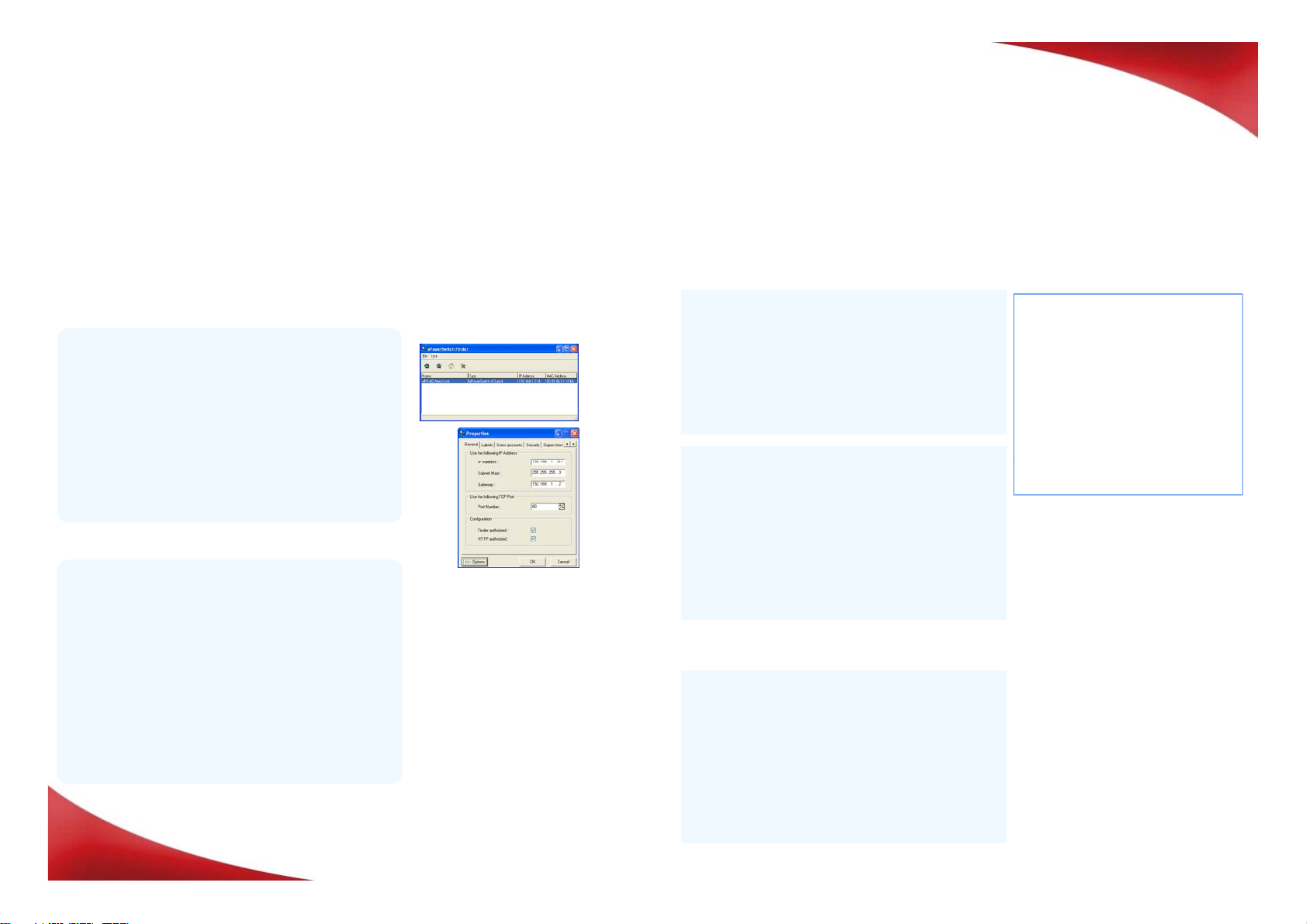
Configuration through the LAN using the Finder
program contained on the CD-ROM
It is the simplest and fastest configuration method if you
use Windows as operating system and allows to configure
your ePowerSwitch 8M+R2 through your local network even
if its network parameters are not compatible with those of
your PC.
1. Start the Finder.exe program.
2 In the tool bar click on the first left button to discover the
ePowerePowerSwitchSwitch 8M+8M+R2R2
Configuration through an RS232 Terminal connection
1. Use the provided RS232 cable to connect the
ePowerSwitch to an available serial port of your PC.
2. Run a Terminal program such as Windows
HyperTerminal.
3. Configure the appropriate serial port @ 9.600, n, 8, 1
and no flow control.
4. On your computer, press <ENTER> until the
configuration menu appears on your screen.
--------------------------------------
NETWORK INTERFACE PARAMETERS:
IP address on LAN is 192.168.100.200
LAN interface's subnet mask is
255.255.255.0
IP address of default gateway to
other networks is 0.0.0.0
IP address of primary DNS server is
0.0.0.0
IP address of secondary DNS server is
0.0.0.0
MISCELLANEOUS:
HTTP Port is 80
Finder program is enabled
HARDWARE PARAMETERS:
Special commands (type /? or /Help)
Configuration through the LAN using a standard
Browser
During the first installation, change temporarily the network
settings of your PC according to the default network
settings of the ePowerSwitch 8M+R2.
Factory network settings of the ePowerSwitch 8M+R2
IP Address: 192.168.100.200 - Port: 80
Gateway: 255.255.255.0
1. Start your Web browser and type following IP address:
http://192.168.100.200/sysadmin.htm
2. Enter the administrator name and password
(default for both = admin)
The home page appears, allowing you to configure the
settings of your ePowerSwitch 8M+R2.
2
.
In
the
tool
bar
,
click
on
the
first
left
button
to
discover
the
ePowerSwitch 8M+R2 connected on your LAN.
3. In the tool bar, click on the second left button and
configure the network parameters.
After configuring the network parameters using one of
the previous methods, start your browser and enter the
address of your ePowerSwitch.
By using the administrator account (default name and
password = admin) you will be able to do all settings and
to control all power outlets.
By using one of the 40 user accounts you will only be
able to control the power outlets for which one the user
has the permission.
HARDWARE
PARAMETERS:
MAC Address is 00.13.F6.01.3C.80
---------------------------------------
]3. Controlling the power outlets over IP
Special
commands
(type
/?
or
/Help)
/initlog Clears the log file
/initadminaccount Restores default administrator
password
/restorefactconf Restores to factory default
settings
/help /? Displays this help