5
Deutsch
2 Hinweise
für den sicheren Gebrauch
Das Gerät entspricht allen relevanten Richtlinien
der EU und ist deshalb mit gekennzeichnet.
WARNUNG
Das Gerät wird mit lebensgefähr-
licher Netzspannung versorgt.
Nehmen Sie deshalb niemals
selbst Eingriffe am Gerät vor und
stecken Sie nichts in die Lüftungsöffnungen. Es
besteht die Gefahr eines elektrischen Schlags.
•
Verwenden Sie das Gerät nur im Innenbereich
und schützen Sie es vor Tropf- und Spritzwas-
ser, hoher Luftfeuchtigkeit und Hitze (zulässi-
ger Einsatztemperaturbereich 0– 40°C).
•
Stellen Sie keine mit Flüssigkeit gefüllten Ge-
fäße, z.B. Trinkgläser, auf das Gerät.
•
Ziehen Sie sofort den Netzstecker aus der
Steckdose,
1.
wenn sichtbare Schäden am Gerät oder am
Netzkabel vorhanden sind,
2.
wenn nach einem Sturz oder Ähnlichem der
Verdacht auf einen Defekt besteht,
3. wenn Funktionsstörungen auftreten.
Geben Sie das Gerät in jedem Fall zur Repa-
ratur in eine Fachwerkstatt.
•
Ziehen Sie den Netzstecker nie am Kabel aus
der Steckdose, fassen Sie immer am Stecker an.
•
Wird das Gerät zweckentfremdet, nicht sicher
montiert, nicht richtig angeschlossen, falsch
bedient oder nicht fachgerecht repariert, kann
keine Haftung für daraus resultierende Sach-
oder Personenschäden und keine Garantie für
das Gerät übernommen werden.
Soll das Gerät endgültig aus dem Betrieb
genommen werden, übergeben Sie es
zur umweltgerechten Entsorgung einem
örtlichen Recyclingbetrieb.
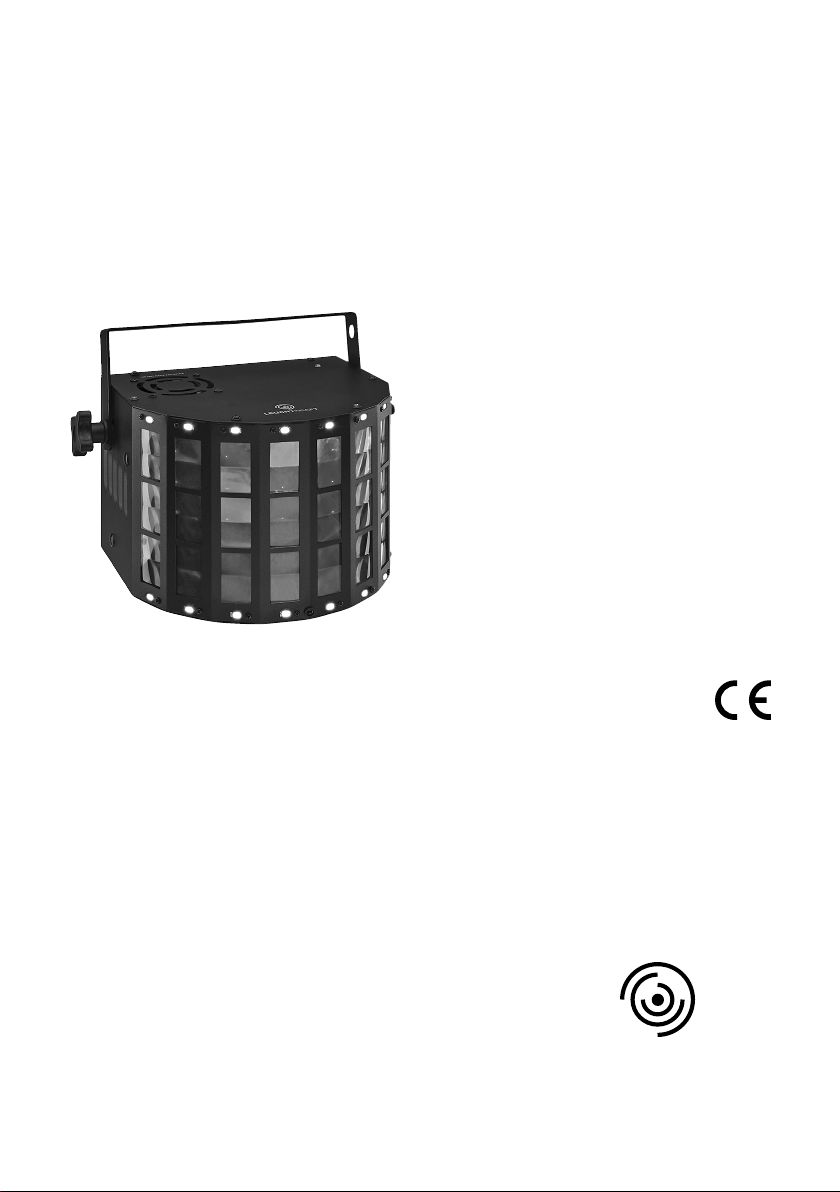
3 Einsatzmöglichkeiten
Das Lichteffektgerät LED-162RGBW erzeugt ro
-
tierende, farbige Lichtmuster und weiße Lauf-
lichteffekte. Es lässt sich z.B. auf Bühnen und
in Diskotheken einsetzen.
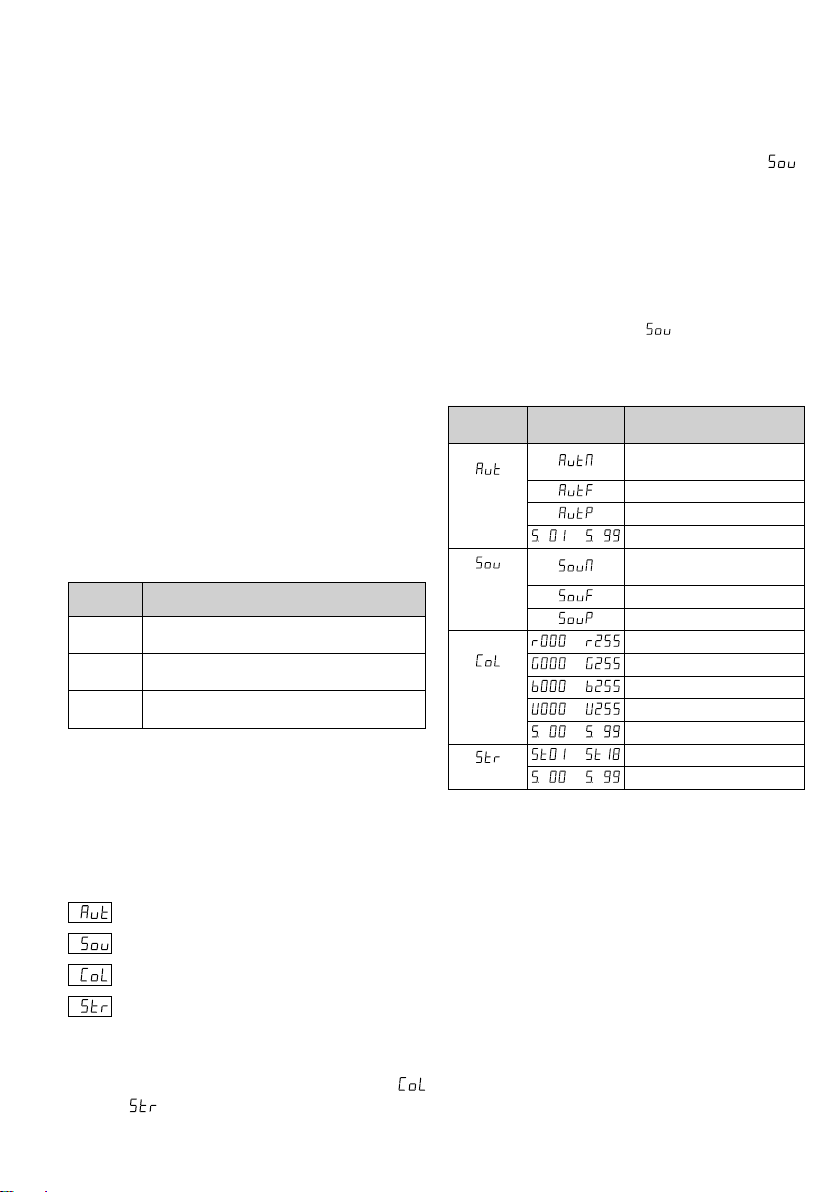
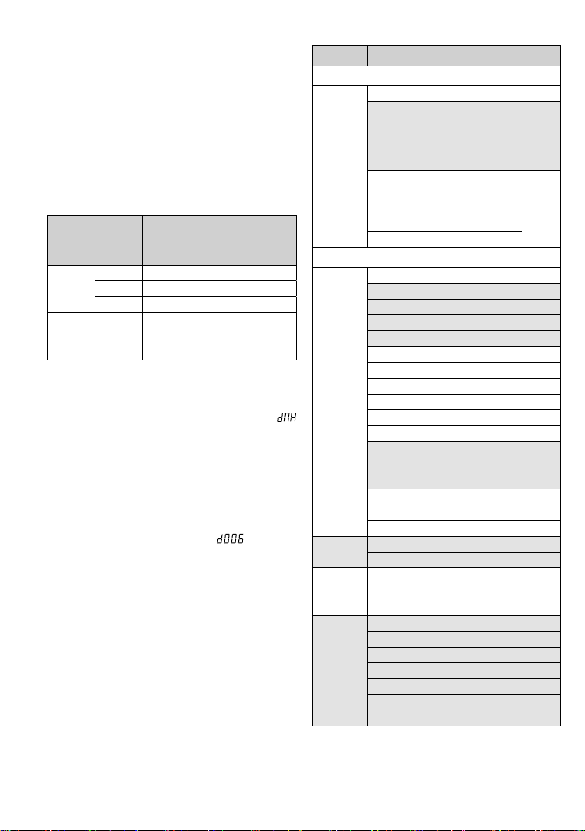
Zur Steuerung über ein DMX-Lichtsteuer-
gerät lässt sich das Gerät über 1 oder 4
DMX-Steuerkanäle betreiben. Es kann aber
auch eigenständig ein Lichtshow-Programm
automatisch oder musikgesteuert projizieren.
Zudem lassen sich mehrere LED-162RGBW
zusammenschalten (Master-Slave-Betrieb), um
synchron Lichteffekte zu erzeugen.
4 Inbetriebnahme
4.1 Installation
•
Platzieren Sie das Gerät so, dass im Betrieb
eine ausreichende Luftzirkulation gewährleis-
tet ist. Die Lüftungsöffnungen des Gehäuses
dürfen auf keinen Fall abgedeckt werden.
•
Der Abstand zum angestrahlten Objekt sollte
mindestens 50cm betragen.
WARNUNG
Wird das Gerät an einer Stelle
installiert, unter der sich Perso-
nen aufhalten können, muss es
zusätzlich gesichert werden, z.B.
durch ein Fangseil. Das Fangseil durch die
Sicherheitsöse (2) führen und so befestigen,
dass der Fallweg des Geräts nicht mehr als
20cm betragen kann.
1)
Das LED-162RGBW über den Montage-
bügel(6) befestigen, z.B. an einer Traverse
mit einer stabilen Montageschraube oder
einer Lichtstrahler-Halterung (C-Haken).
2) Zum Ausrichten des Geräts die beiden Fest-
stellschrauben (1) lösen. Die gewünschte Nei-
gung einstellen und die Schrauben wieder
festziehen.
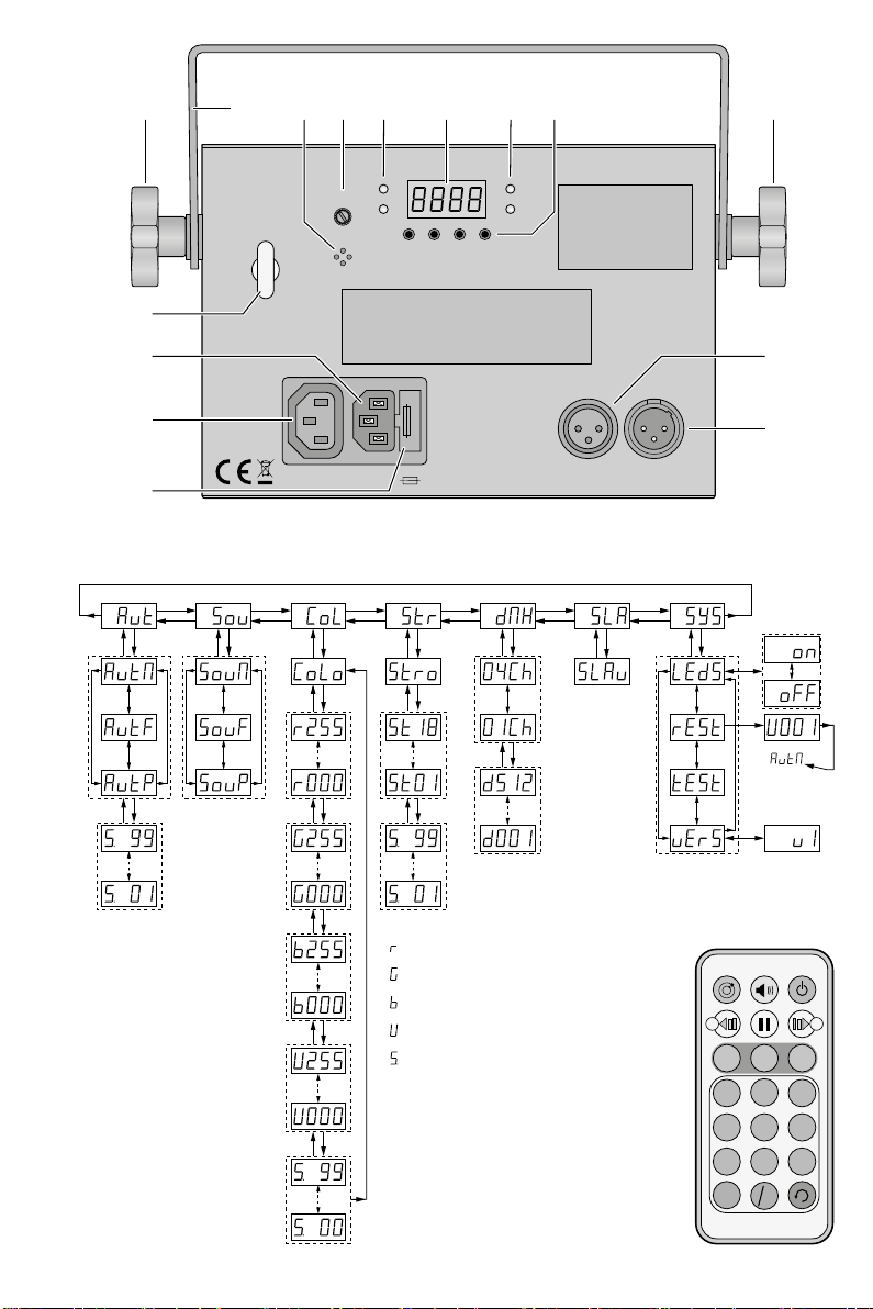
4.2 Stromversorgung
Das Gerät über die Netzbuchse (3) mit dem
beiliegenden Netzkabel an eine Steckdose
(230V/50Hz) anschließen. Damit ist das Gerät
eingeschaltet:
Nach dem Startvorgang ist der zuletzt gewählte
Betriebsmodus eingeschaltet. Das Display (10)
zeigt den Modus ca. 30s lang an. Dann leuchtet
nur noch ein Punkt im Display als Betriebsanzei-
ge. Sobald eine der Bedientasten (12) gedrückt
wird, leuchtet das Display wieder für 30s.
WARNUNG
Blicken Sie nicht für längere Zeit
direkt in die Lichtquelle, das kann
zu Augenschäden führen.
Beachten Sie, dass sehr schnelle Lichtwechsel
bei Epileptikern und bei fotosensiblen Men-
schen epileptische Anfälle auslösen können!