Leuze electronic DLSP 160S Parts list manual

Parallel optical data transmission DLSP 160S
Technical Description

© All rights reserved, in particular the rights of reproduction, and translation. Duplication or reproduction in
any form (print, microfilm or data) may only be carried out with the expressed written consent of
Leuze electronic GmbH + Co.
We reserve the right to make changes for the Technical improvement of the product.

Contents
1 General ........................................................................................................... 2
1.1 Explanation of symbols .............................................................................. 2
1.2 Important terms .......................................................................................... 2
1.3 Declaration of conformity ........................................................................... 3
2 Safety Notices................................................................................................ 4
2.1 Safety standard .......................................................................................... 4
2.2 Intended use .............................................................................................. 4
2.3 Organisational measures ........................................................................... 4
3 Description..................................................................................................... 5
3.1 Survey of parallel data transmission systems ............................................ 5
3.2 Features of the DLSP 160..........................................................................5
3.3 Structure.....................................................................................................6
3.4 Functional characteristics........................................................................... 7
3.4.1 Transmit/receive mode ......................................................................... 7
3.4.2 Addressing ............................................................................................8
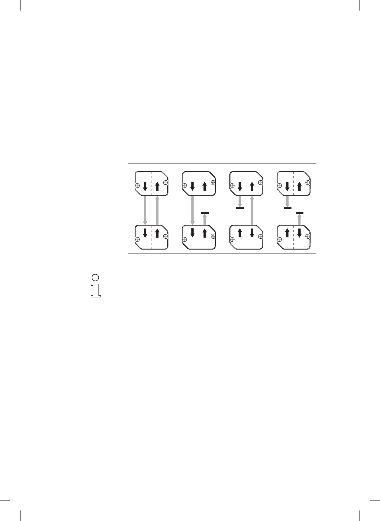
3.4.3 Storage of data outputs.........................................................................8
3.4.4 Signal profile ......................................................................................... 9
4 Applications................................................................................................. 11
4.1 Simple data transmission .........................................................................11
4.2 Operation of several DLSPs - extending the number of channels ........... 11
4.3 Bus operation ........................................................................................... 12
4.4 Optical data storage .................................................................................12
5 Specifications ..............................................................................................13
5.1 Characteristic data ...................................................................................13
5.2 Mechanical data ....................................................................................... 14
5.3 Ambient conditions................................................................................... 14
5.4 Electrical data...........................................................................................14
6 Installation and commissioning................................................................. 16
6.1 Installation ................................................................................................ 16
6.2 Commissioning......................................................................................... 17
6.2.1 Setting the DLSP ................................................................................ 17
6.2.2 Performance test.................................................................................17
6.2.3 Sensitivity adjustment .........................................................................17
7 Maintenance................................................................................................. 18
8 Faults and their remedy..............................................................................18
9 Order designations ..................................................................................... 19
Leuze electronic DLSP 160S 1

1 General
1.1 Explanation of symbols
The symbols used in this technical description are explained below.
Danger !
This symbol is positioned in front of remarks or warnings which must be heeded
without fail. Failure to comply with these instructions can lead to personal injury or
damage to property.
Notice
This symbol indicates places in the text where supplementary information is offered
on the installation and handling of data transmission units.
☞Cross reference to other chapters or other documentation.
➜This symbol indicates activities which must be carried out.
Italics To permit you to find information quickly, key words are listed in the left-hand col-
umn in italics.
1.2 Important terms
DLSP Type designation for Leuze electronic data transmission units with parallel inter-
face. The transmitter and receiver are accommodated in a single housing.
DLSP 160S Type designation for the electronic and display unit.
AT 160xx Type designation for the connection unit. "xx" stands for the
various configurations.
Tristate High-resistance status of an output. In this status, for example, connected bus con-
ductors are not subjected to load.
Semi-duplex Transmission and reception of data take place in alternating sequence.
2 DLSP 160S Leuze electronic

1.3 Declaration of conformity
The paralle optical data transmission units DLSP 160 have been developed and
produced in accordance with the applicable European standards and directives.
Notice
The corresponding declaration of conformity can be requested from the manufactu-
rer.
The manufacturer of the product, Leuze electronic GmbH + Co. in
D-73277 Owen/Teck, possesses a certified quality management system in accord-
ance with ISO 9001.
Leuze electronic DLSP 160S 3

2 Safety Notices
2.1 Safety standard
The data transmission unit DLSP has been developed, produced and tested taking
into account the applicable safety standards and is in compliance with the state of
the art.
2.2 Intended use
Attention !
The protection of personnel and device cannot be guaranteed if the device is opera-
ted in a manner not corresponding to its intended use.
Data transmission units of the DLSP series may only be used in areas in which in-
terruption of data transmission, for example as a result of masking of the transmit-
ter or receiver lens, cannot lead to damage or personal injury.
Fields of application The DLSP is particularly suited to the following fields of application:
•Automatic guided vehicle systems to VBG 12b
•Rack handling devices, warehouse transport systems etc.
•Trolley conveyors
•Optical rotary transfer units
•Storage and handling systems
•Optical data storage systems
2.3 Organisational measures
Documentation All specifications made in this technical description, in particular the section "safety
remarks" must be observed without fail.
The technical description should be kept readily accessible at all times.
Safety regulations All applicable legislation and rulings of the relevant professional associations must
also be complied with.
Qualified staff Installation, commissioning and maintenance may only be carried out by suitably
qualified staff.
Electrical work may only be carried out by qualified electricians.
Maintenance and repair All maintenance work on the DLSP must be carried out in accordance with the in-
structions in this manual. Repairs may only performed by the Leuze electronic after-
sales service.
4 DLSP 160S Leuze electronic

3 Description
3.1 Survey of parallel data transmission systems
Functional characteristics The data transmission unit DLSP is a no-contact device for the transmission of
electrical signals. Each unit is equipped with 8 inputs and outputs. The transmitter
transforms the input signals into a serial telegram which is carried by an invisible
light beam to the receiver. Here, the telegram is read out again in the form of elec-
trical signals at the outputs. Data transmission takes place simultaneously in both
directions.
Application Because the transmission method involves no contact and is insensitive to inter-
ference, the DLSP can be used even in tough industrial environments, in particular
where movement is unavoidable.
Using the DLSP, all types of vehicle (AGVS, rack handling vehicles, warehouse
transport systems etc.) can now be effectively controlled without cumbersome trail-
ing cables and temperamental sliding contacts.
Fig. 1 DLSP
3.2 Features of the DLSP 160
The data transmission unit DLSP is characterized by the following features:
During installation •Minimal space requirement (base plate 75 x 46 mm2)
•Rapid assembly due to two-part structure with terminal plate or mounting and a
plug-on electronic unit
•Quickly installed using eff icient connection methods (solder terminals, ribbon
cable, or spring-type terminals)
•Transmitter and receiver in a single housing (same units)
•Simple, rapid alignment with wide beam angle
•Simple commissioning with display of inputs and outputs
•No transmission parameter setting work required
Leuze electronic DLSP 160S 5

In operation •Very high transmission rate (max. 400 μs per telegram)
•Reliable transmission due to ample performance reserve
•Insensitive to interference
•Insensitive to outside light
•Multiple transmission repeats
•Storage of output signals
•Adjustable transmit and receive addresses
3.3 Structure
Housing The data transmission unit DLSP is accommodated in a durable housing. Each unit
comprises a transmitter and receiver. The housing is protected against the effects
of splash water (IP 65).
Displays There are 18 LEDs located on the front of the unit which indicate the operating
status of the DLSP, as well as signals to the inputs and outputs.
Setting The range can be set by altering the sensitivity of the receiver at a potentiometer.
Installation The connection unit AT 160xx is prepared for screw mounting onto panels or
brackets (dimensional drawing: see Specifications).
Connection Depending on the configuration of the connection unit, the DLSP is connected by
means of solder terminals, spring-type terminals or ribbon cable with crimp-type
connection. Cable feed-in is either at the side or through the rear wall by means of
a cable gland.
Fig. 2 DLSP structure
1 Electronic and display unit DLSP 160S
2 Sensitivity setting
3 Transmit/receive window
4 Input/output status displays
5 Connection unit AT 160xx (mounting, connection)
6 Cable gland (rear wall)
7 Cable gland (side)
12 3 4567
6 DLSP 160S Leuze electronic

3.4 Functional characteristics
3.4.1 Transmit/receive mode
Transmission Every DLSP comprises a transmitter and a receiver. The transmitter transforms ac-
tive data signals at the 8 data inputs into a serial telegram. The transformation pro-
cess is performed using pulse pause modulation (PPM). The logic statuses "O"
and "l " at the inputs correspond to pauses of differing lengths between 2 pulses.
Signal transmission The serial telegram is converted into a modulated light signal. Transmission takes
place using invisible infrared light. The transmission time is around 400 μs (8 sig-
nals in each direction).
Receiving The receiver reconstructs the serial telegram from the received light signal (de-
modulation).
Data output Following serial-parallel transformation, the signals are available at the 8 outputs.
The output signals can be optionally saved or not saved.
Data safety The high degree of data safety offered by the DLSP is guaranteed by a check of
amplitude, address and parity, repetition of each telegram and the indication of
valid data with the Data Valid (DV) signal.
Transmission in
parallel operation
Transmission takes place using the burst mode, i.e. each telegram is transmitted in
the form of a short package with a long pause between 2 telegrams. The scanning
ratio is appr. 1:100. Data is actually being transmitted for only 1 % of the unit’s duty
cycle.
Notice
During parallel operation of several DLSPs, the possibility of mutual interaction can-
not be excluded. If interference between neighbouring transmissions paths (see
page 13) occurs, mount small metal lateral shielding plates between the individual
units. They should extend approx. 5 - 10 cm beyond the front surface of the unit.
Both the units forming a transmission path can transmit and receive. Data is trans-
mitted and received using the handshake mode, i.e. in alternating sequence. Syn-
chronization is taken care of automatically by the DLSP.
Benefit Both the units forming a transmission path operate on an identical basis, i.e. no
master/slave operation and no need for different settings.
Fig. 3 Transmit/receive principle
x
x
8x
8x
Se
E
E
Se
Leuze electronic DLSP 160S 7

3.4.2 Addressing
The DLSP can be addressed by means of DIP switches. Separate setting of four
different addresses is possible using 2 x 2 DIP switches for the transmitter and re-
ceiver.
Data transmission is only possible if the transmit and receive address of a trans-
mission direction are in agreement. The transmit and receive addresses of one unit
do not need to be identical.
Benefits This permits several transmission paths to be set up even in restricted conditions,
with up to 32 parallel transmission channels achievable in both directions. By ad-
dress differentiation between transmitter and receiver, it is possible to define inter-
leaved transmission ranges.
Fig. 4 Interleaved transmission
Notice
When operating several DLSP units in parallel, a minimum distance between the
single units has to be kept. This minimum distance depends on the application, e.g.:
•Transmission while a vehicle is passing by
•Constant transmission with variable transmission distance (see "Transmission in
parallel operation" above)
3.4.3 Storage of data outputs
The DLSP’s data outputs can be stored if required. In this case, when the light
beam is interrupted, the output data is retained.
The setting "save (0) / do not save (1)" is carried out using a DIP switch.
Benefit Following a data exchange, the outputs can be scanned at any time.
0 2
0
1
01
0
1
2 1
0
1
1 2
0
1
8 DLSP 160S Leuze electronic

Fig. 5 Storage / non-storage of data outputs
3.4.4 Signal profile
Fig. 6 demonstrates the signal profile from the transmitter to the receiver during
transmission of 1 serial telegram.
Fig. 6 Signal profile
Data inputs (DI) The signals at the 8 data inputs are transformed into a serial telegram with a parity
bit and an address, and transmitted.
Transmit input (TX) With the positive flank of the TX signal, the waiting data is taken over by the inputs
and transmitted. The transmit signal must be applied for at least 300 μs.
Continuous activation of TX is possible, in which case the input data is transmitted
continuously.
In the case of inactivation, transmission of the current telegram is completed. TX
does not affect the receiving characteristics.
Benefits •The receiver never receives garbled telegrams
•Point-by-point data transmission is possible (transmission of a single telegram)
Data valid output (DV) This output signals the presence of valid data at the receiver. In the event of a
faulty transmission or if the light beam has been interrupted, the output remains in-
active ("O").
Data outputs (DO) In the no-signal status, the outputs are set at "O", active signals are indicated by "l".
Interruption of beam
Transmission data
Data valid
Outputs- not saved
Outputs - saved
Transmitter
Receiver (not stored)
Receiver (control via output enable)
TX
DI
DV
DO
OE
DO
Leuze electronic DLSP 160S 9

Notice
If no data transmission takes place (e.g. TX in "O" status),
all 8 outputs are set to "O".
Output enable input (OE) If a "l" is applied at this input, the outputs are switched to the active operation
status, i.e. it is possible for received signals to be read out. A "0" at this input re-
sults in "0" at all the outputs and the green indicator LEDs.
Benefits The status of output drivers can easily be automatically checked by a programm-
able control system. "O" at the OE generally forces a signal change at the outputs.
10 DLSP 160S Leuze electronic

4 Applications
4.1 Simple data transmission
The DLSP permits non-contact data exchange, for instance between industrial
trucks (automatic guided vehicle systems) and fixed stations.
Benefits The wide optical beam angle does away with the need for unit adjustment. Even
where the automatic guided vehicle deviates from the ideal travel path, reliable
data transmission still takes place. Transmission is possible while the vehicle travel-
s past the fixed station.
Fig. 7 Data exchange between the AGVS and the fixed station
4.2 Operation of several DLSPs - extending the number of channels
The facility for separate setting of the transmit and receive addresses permits
•parallel transmission of max. 32 signals per direction,
•interleaved transmission ranges.
With 2 (4) units operating in parallel, it is possible to transmit up to 16 (32) signals
from the vehicle to the fixed station and back.
•By using different addresses, it is possible to prevent transmission between the
fixed stations (1).
•By using different addresses, it is possible to prevent transmission between fixed
stations positioned opposite each other (2).
Fig. 8 Several DLSPs with addressing
1
2
Leuze electronic DLSP 160S 11

4.3 Bus operation
The DLSP can also be used within bus systems, provided the following conditions
exist:
•The 8 data inputs must be connected to the data outputs.
•For control of the transmission direction, the signals "Transmit" (TX) and "Output
enable" (OE) are used.
In this way, it is possible to create, for example, isolated partial bus systems. By
using up to 4 DLSP units per side, 32 bit wide bus systems can be configured.
Fig. 9 DLSP in bus operation
4.4 Optical data storage
The DSLP offers the possibility of storing the output signals.
This function can be used to configure the DLSP as a data storage device.
Application example:
•Information from a fixed station is transferred to a mobile station (storage device).
These data are further directed to a corresponding fixed station.
DLSP setting - storage device
•Storage mode
•Connect inputs with outputs
•Transmit address: same as station receive addres
•Receive address: same as fixed station transmit address (output point)
DO1
DO8
DO2
DI1
DI8
DI2
TX
OE
DI1
DI8
DI2
DO1
DO8
DO2
TX
OE
12 DLSP 160S Leuze electronic

5 Specifications
5.1 Characteristic data
Manufacturer Leuze electronic GmbH + Co.
D-73277 Owen-Teck
Transmission medium IR modulated light
Modulation Pulse Pause Modulation (PPM)
Range 0 - 1.8 m
Time per data exchange < 400 μs
Resistance to outside light 30 klux
Optical beam angle +/- 20°
EMC (IEC 801.4) Supply: severity 4
I/0 conductor: severity 3
Transmit / receive characteristics
(all specifications in cm)
Fig. 10 Transmit / receive characteristics
Operating range Limiting range
D
L
S
P
0
20
40
60
20
40
0 20 40 60 80 100 120 140 160 180 200 220 240 260 280 60
Leuze electronic DLSP 160S 13

5.2 Mechanical data
Housing Aluminium
Surface finish Anodized
Colour Red/black
Dimensions 75 x 55 x 45 mm (W x H x D)
Terminals Soldered, flat ribbon cable or spring-type
Fixture 2 M4 screws
Protection class IP 65 (splash water protection)
Fig. 11 Dimensions (mm)
5.3 Ambient conditions
Ambient temperature -20°C to +60°C
Storage temperature -30°C to +70°C
8
10,5
45
37,5
16,5
Blindstopfen PG9
IN
OUT DV
TX
46,6
55
16,5
66,6
75
ca.93
PG9 Befestigungsbohrungen
ø4,2 (2x)
4,2
4,2
Mounting holes
Blanking plug PG9
55
18
7,5
17,6
38
IN
OUT DV
TX
46,6
66,6
75
ca.95
PG13,5 Befestigungsbohrungen
ø4,2 (2x)
4,2
4,2
55
Mounting holes
14 DLSP 160S Leuze electronic

5.4 Electrical data
Supply
Operating voltage 16-35V DC
Residual ripple 15%
Current consumption appr. 130 mA (all LEDs on)
Inputs
Data inputs (Data IN) max. 35 V DC, 4.5 mA
Transmit (TX) H >= 8 V, L <= 5 V
Output enable (OE) H >= 8 V, L <= 5 V
Fig. 12 Input circuit
Outputs
Data outputs (DO) High-side driver, short-circuit proof
H >= UB - 2V, L <= 1.5 V
max. load 2 outputs each 250 mA
3 outputs each 160 mA
4 outputs each 120 mA
5 outputs each 100 mA
6 outputs each 80 mA
7 outputs each 70 mA
8 outputs each 60 mA
With a total data output load greater than 0.6 A, the back-up fuse triggers.
The supply voltage must be switched off and back on again one time in order to
activate the back-up fuse.
Data valid (DV) High side driver, short circuit proof
max. load 250 mA
Fig. 13 Output circuit
C - MOS
6,8 k
LED rot
8 - 35 V
LED Red
6,8 k
LED
grün
Transienten-
schutz
zentraler Kurzschluß –
Schutz
– Daten – – Data valid (DV) –
Kurzschluß –
Schutz
LED
gelb
protection protection
Transient
protection LED
Green
LED
Yellow
- Data -
Central short circuit
- Data valid (DV) -
Short circuit
Leuze electronic DLSP 160S 15

6 Installation and commissioning
6.1 Installation
➜Fasten the DLSP in position by tightening two M4 fixing screws with washers
and circlips.
➜Prepare the connecting cable
Cable cross-section 0.14-0.5 mm2
Cable outside diameter 5 - 9 mm (PG 9) or 13 mm (PG 13.5)
Shielding only necessary in case of strong interference fields
➜Unscrew the housing
➜Guide the connecting cables through the cable glands and solder in
accordance with the plug assignment plan or
crimp the ribbon cable in the crimping plug or
insert the cores in the spring-type terminals and clamp.
Signal Description Assignment
Solder terminal
Ribbon cable
Spring terminal
PE Protective earth 1 1
UBOperating voltage
16 – 35 VDC
22
GND Earth
operating voltage
33
DI 8 Data input 8 4 4
DI 7 Data input 7 5 5
DI 6 Data input 6 6 6
DI 5 Data input 5 7 7
DI 4 Data input 4 8 8
DI 3 Data input 3 9 9
DI 2 Data input 2 10 10
DI 1 Data input 1 11 11
DV Data valid 15 13
DO 8 Data output 8 16 14
DO 7 Data output 7 17 15
DO 6 Data output 6 18 16
DO 5 Data output 5 19 17
DO 4 Data output 4 20 18
DO 3 Data output 3 21 19
DO 2 Data output 2 22 20
DO 1 Data output 1 23 21
OE Output enable 24 22
TX Transmit data 25 23
24/NC
25/NC
113
25
14
1
13
12
24
Solder terminal
Ribbon cable
Spring-type terminal
Fig. 14 Plug assignment
16 DLSP 160S Leuze electronic

6.2 Commissioning
6.2.1 Setting the DLSP
➜Setting the transmit and receive address.
➜Setting the output storage characteristics.
Fig. 15 Setting the DLSP
6.2.2 Performance test
➜Switch on the supply voltage.
➜Apply one or more input signals.
➜Transmit data (input TX at "l").
The relevant input LEDs light up in red.
➜Receive data (input Output enable at "1")
➜Check receiver:
•the relevant output LEDs light up in green,
•the "Data valid" display lights up in yellow.
➜Repeat the process for the other transmission direction.
6.2.3 Sensitivity adjustment
➜Create the worst transmission conditions which can conceivably occur during
use:
•greatest possible distance,
•greatest possible lateral offset.
➜At the first unit, remove the cover over the potentiometer for sensitivity ad-
justment.
➜Turn the potentiometer as far to the right as it will go.
➜Then turn the potentiometer slowly to the left until the display "Data valid"
goes out at the unit positioned opposite.
➜Turn the potentiometer around back to the right by around 1/4 turn.
➜Replace the cover over the potentiometer.
➜Repeat the process at the other DLSP.
1
0
Empfangsadressen
Sendeadressen
speichern nicht speichern
0
1
2
3
0
1
2
3
Do not store Store
Receive adresses
Transmit adresses
Leuze electronic DLSP 160S 17

7 Maintenance
The DLSP 160 data transmission units are maintenance-free.
➜Clean the transmit/receive window at the DLSP regularly. For cleaning, use a
soft cloth and a cleaning agent (standard commercially available glass clea-
ner).
Attention
Do not use aggressive cleaning agents such as thinner or acetone for cleaning the
device. These can destroy the window.
8 Faults and their remedy
Fault Possible cause Remedy
No data transmission, all LEDs
are off.
Power supply fuse has blown.
No power supply.
Connection fault.
Check fuses.
Check power supply.
Check solder, plug-in terminals in the
DLSP.
No data transmission, some
LEDs are on.
Window requires cleaning.
Incorrect addressing.
Sensitivity of receiver incorrectly
adjusted.
No TX signal (the TX LED in the
transmitter is not alight).
No OE signal (DV LED is on at
the receiver).
Clean window.
Check transmit and receive addresses at
both DLSPs.
Check settings (page 17)
Check solder and plug-in terminals in the
DLSP. Check signalling.
Check solder and plug-in terminals in the
DLSP. Check signalling.
No data transmission, LEDs
flicker.
Inadequate shielding.
Electrical earth is connected to
housing earth.
Major interference fields in close
proximity.
Check shielding.
Separate two earth connections.
Provide adequate insulation between
DLSP and underlay.
Transmission error. Influence from parallel or
consecutive transmission paths.
Power supply earth is connected
to housing.
Check transmit and receive addresses at
all DLSPS. For every transmission path, a
different address must be selected.
Isolate the power supply earth from the
housing.
18 DLSP 160S Leuze electronic
Table of contents
Other Leuze electronic Microphone System manuals
Popular Microphone System manuals by other brands

Sennheiser
Sennheiser Esfera SPM8000 instruction manual

Bin Master
Bin Master WR-90 Series instruction manual

Sound Sation
Sound Sation WF-D290 user manual

IMG STAGE LINE
IMG STAGE LINE TXS-880 instruction manual

Smart Technologies
Smart Technologies SMART Audio System 240 Installation and user guide

Hybrid+
Hybrid+ U-AV user manual