Level Pro ULTRAPRO 1000 User manual

Read carefully the instructions published in this manual before the rst use of the level meter. Keep the manual
at a safe place. The manufacturer reserves the right to implement changes without prior notice.
INSTRUCTION MANUAL
průmyslová elektronika
Ultrasonic level meters ULTRAPRO 1000
Firmware: v.2.0
Reliable Non-Contact Level


Table of conTenTs
1 . Measuring principle .................................................................................................................3
2 . Range of applications ..............................................................................................................3
3 . Variants of sensors ..................................................................................................................3
4 . Dimensional drawings .............................................................................................................4
5 . Installation and putting into operation ..................................................................................4
6. Installation instructions ..........................................................................................................5
7. Electrical connection ...............................................................................................................9
8. Examples of UltraPro 1000 connection ...............................................................................10
8.1 . Wiring diagram of the level meter with current output and PDU unit .................................10
8.2 . WiringdiagramofthelevelmeterwithcurrentoutputandPDUunit ..............................
in versions for explosive areas ..........................................................................................11
8 .3 . WiringdiagramofthelevelmeterwithcurrentoutputandMGUunit ................................13
8 .4 . WiringdiagramofthelevelmeterwithModbus/RS485andMGUunit ...........................13
8 .5 . WiringdiagramofthelevelmeterwithModbus/RS485andPDUunit ............................13
9 . Set-up elements .......................................................................................................................14
10. Status signalization ................................................................................................................14
11 . Operation and setting ............................................................................................................15
10.1 . Basicconguration ..........................................................................................................15
10.2 . Servicesettings ...............................................................................................................18
10 .3 . Additionalfunctions .........................................................................................................20
12. HART®
communication protocol ...........................................................................................22
13. Modbus®
communication protocol ........................................................................................23
14 . Order code ..............................................................................................................................23
15 . Accessories ............................................................................................................................23
16 . Safety, protection, compatibility and explosion proof .......................................................24
17 . Use, manipulation and maintenance ....................................................................................24
18 . Marking of labels ....................................................................................................................25
19 . Menu structure .......................................................................................................................27
20 . Specification .........................................................................................................................28
21 . Packing, shipping and storage .............................................................................................30

UltraPro-1000 © Levelpro, s.r.o.
3
1 .
Measuring principle
UltrasoniclevelmeterUltrapro UPS® 1000 Series is a compact measuring device consisting of
two parts - main level meter(thebodywithmeasuringelectronics)and the displaymodule.Using
the electroacoustic converter, the level meter transmits a sequence of ultrasonic pulses that
spread towards the surface level. The converter recuperates reflected acoustic waves that are
subsequently processed in the electronic module. The Utraflo filters out interfering signals,
compares the cleaned received signal with the false reflection map (e.g. from mixers, ladders,
reinforcementetc.)andselectsasuitablereflection(echo).Basedontheperiodduringwhichthe
individual pulses spread towards the surface level and back and based on the measured
temperatureinthetank,theinstantdistancetothe surface level is calculated. According to the
levelheight,thelevelmeteroutputissetandthemeasuredvalueisshownonthedisplay.
2 .
range of applicaTions
Forcontinuousnon-contactlevelmeasurementofliquids(watersolutions,seweragewater,etc.),
mashandpastematerials(sediments,sticks,resinsetc.)inclosedoropenvessels,sumps,reser-
voirsandopenchannels.Incasethelevelofbulk-solidmaterialsismeasured,themeasurement
rangeisreduced.Thelevelmeterscancontinuouslymeasurelevelsofbulk-solidmaterialswith
a low concentration of dust particles. Consult the manufacturer on recommended use of the level
meterforbulk-solidmaterials.
3 .
VarianTs of sensors
All operations described in this instruction manual have to be carried out only by trained
personnel or an accredited person. Warranty and post warranty service must be exclusively
carried out by the manufacturer.
Improper use, installation or set-up of the level meter can result in crashes in the application
(overlling of the tank or damage of system components).
The manufacturer is not responsible for improper use, losses of work caused by either direct or
indirect damage, and for expenses incurred during installation or use of the level meter.
safeTy
UPS-1000 –02 Measuring range from 0.15m to 2m, plasticPVDFtransmitter,mechanical
connectionwiththread1".
UPS-1000–06 Measuring range from 0.25m to 6m, plasticPVDFtransmitter,
mechanicalconnectionwiththreadG1½".
UPS-1000–10 Measuring range from 0.4m to 10m PVDFtransmitter,
mechanical connection with thread 2¼".
UPS-1000-20 Measuring range from 0.5m to 20m, PVDFtransmitter,mechanical
connectionwithaluminiumalloyange.

4
© Levelpro, s.r.o. UltraPro-1000
4 .
DiMensional Drawings
UPS-1000-02
Pg11 cable gland
Ground terminal
variant UPS -with protective
conductor
UPS-1000–06
UPS-1000-20
UPS-1000–10
This procedure includes the following three steps.
•
insTallaTion
•
elecTric connecTion
•
seTTing
5 .
insTallaTion anD puTTing inTo operaTion

Ultrapro-1000 © Levelpro, s.r.o.
5
Fig. 2: Level meter dead zone
m – Dead zone
(blind zone, blocking distance)
6 .
InstallatIon InstructIons
•Install the level meter in the vertical positionintotheupperlidofthetankorreservoirusingaweld-
ingflange,afasteningnutoraflangesothatthe
levelmeteraxisisperpendiculartothesurfacelevel
ofthemeasuredliquid(Fig.1).
• Themin.dimensional parameters to install the level
meterintoalidoraceilingofatankaregiveninFig.3.
•When installing in an open channel(reservoir,drain
etc.),installthelevelmeterontoabracketascloseas
possibletotheexpectedmax.level.
•Inconnectionwiththemeasurementprinciple,nosig-
nals reectedintheareaimmediatelyunderthelevel
metercanbeevaluated.The zone(Fig.2)determines
themin.distancepossiblebetweenthelevelmeter
and the highest surface level. The min. distances to
themediumaregiveninthechapter"Specications".
•It is necessary to install the level meter so that the
bin level cannot interfere with the dead zone when
filled uptothemaximum.Ifthemeasuredlevelinter-
fereswiththedeadzone,thelevelmeterwillnot
work
properly.
Fig. 1: Recommended installation in
the tank
Fig. 3: Installation distance from the tank wall
•Ifthemaximumsurfacelevelinthetankinterfereswiththedeadzone,thelevelmeterhas
tobemountedintoahigherinstallation neck.Inthisway,thetankcanbefi lednearlyupto
themaximumvolume.Theinnernecksurfacehastobeevenandsmooth(withoutedgesand
weldedjoints);theinneredgeshouldberoundedwheretheultrasonicwaveleavesthepipe.The
neckdiametershouldbeaslargeaspossiblebuttheneckheightshouldbeaslowaspossible.
RecommendeddimensionsoftheinputneckaregiveninFig.4.
UPS 1000–02 ; 10 d > 1/12 c
(min. 200 mm)
UPS 1000–06 d > 1/8 c
(min. 200 mm)
UPS 1000–20 d > 1/10 c
(min. 200 mm)
Fig. 4: Possible installation of the installation neck
a – Neck height
b – Neck width
m – Dead zone (blind zone, blocking dist.)
UPS 1000–02 ; 06 a < 3 b
b > 100 mm
UPS 1000–10 a < 1,5 b
b > 100 mm
UPS 1000–20 a < 1,5 b
b > 150 mm
d – Distance from
the tank wall
c – Maximum reach
of the level meter

6
© Levelpro, s.r.o. UltraPro 1000
•Iftheemittedacousticsignalofthelevelmeterisaffectedbynearobjects(roughnessonwalls
ofthetank,variouspartitions,mixersetc.),itisnecessarytomapfalsereectionsbyactivating
themode"TEACHING".Incaseofinstalledmixers,itisnecessarytoputthemixerstoposition
underthelevelmeter(directthemixerpaddletotheultrasonicsignalbeam)(Fig.5and6).
•Donotinstallthelevelmeterinorabovethefillingpoint(Fig.7).
Fig. 5: False echo from obstacles in the tank Fig. 6: False echo from the mixer paddle
Fig. 7: Level meter installation outside the inuence of lling
•Incasethelevelofbulksolids beingthe
measurementrangeisreducedDuetoabsorp-
tionofacousticwavesbymedium,the
shorteningofthemeasuringrangecan be
reduced byupto 50% depending on the
medium and the particle size. We therefore
recommend selecting a level meter with greater
range than the maximum range of measuring
the medium. It is also recommended to use a
directionalhorn(seeimage8),whichwill
increase the rangethemeasuringrange,
(concentratesacousticenergy)whilepre-
servingthesamebeamangle,andimproves
thesensitivitywhenreceivingthereflected
echo. We recommend to consult the use with the
manufacturer.
Fig. 8: Level meter installation in silo or hopper
horn
adapter

UltraPro 1000 © Levelpro, s.r.o.
7
!
!
•Scatteringorattenuationofthe
ultrasonic signal can result if the
surfacelevelhasbeenmoderate-
ly stirred or rippled(bya mixer,
comingliquidetc.). Itcanresult
in reduction of the measurement
rangeorunreliablefunctionofthe
levelmeter(Fig.10).
•Rotatingmixer blades can cause
thatthesurfaceisstirred,whichre-
sultsinfalsereectionsoftheultra-
sonic signal from the surface level
andunreliableoperationofthe
levelmeter(Fig.13).(obr.11).For a
rippled or swirling level, you can
use the directional horn to elimi-
nate scattering of the ultrasonic
signal.
•Duringfiling,mixingandotherprocesses,foam can arise
on the surface level of the measured liquid.Thefoam
absorbstheultrasonicsignal which may cause malfunction
of the level meter (Fig.9).Forsuchcases,itisnecessaryto
setup"SENSITIVITY"modeto"high"orto contactthe
manufacturer. Incaseofathinlayeroffoam,itisalso
recommendedtousethe directionalhornforimproving
receiptoftheecho.
Fig. 9: Foam on the surface
Fig. 10: Moderately stirred
surface
Fig. 11: Intensely stirred surface
•If the level sensor is mounted to
bottlenecksandplaceswithba-
rriers,ornearunevenwallsorthe
fi lingarea,wherethetransmissi-
onsignalcouldbedistorted,we
recommendusingaguidetube
(acoustichorn).Thetubemustbe
made from a single material with a
smooth inner surface (see image
12a,12b).Theminimumtubedia-
metermusthavethedimension"b"
according to image 4 on page 5.
Afterinstalling,youmustperform
theprocedure"LEARNING".We
recommend consulting with the
manufacture on the construction of
theguidetube.
Obr. 12a: Short guide tube
installation
ventilation
holes
sleeves for
mounting
Obr. 12b: Total guide tube
installation

8
© Levelpro, s.r.o. UltraPro 1000
•Thelevelmetermustnotbeinstalledinplaceswithdirectso-
lar radiationandmustbeprotectedagainstweathereffects.
•If the installation in places with direct solar radiation is inevi-
table,itisnecessarytomountashielding coverabovethe
levelmeter (Fig.13).
•Itissuitabletorunthecableunderacablebushing(obliquely
downinslack)accordingtoFig.14topreventpenetration
of humidity.Thentherainandcondensingwatercanfl w
offfreely.
•Thecablebushingandconnectorhavetobesufciently
tightenedtopreventpenetrationofhumidity.
•Tolowertheminimumdistancetothemeasuredmedium,
a reection boardmadefromsolid,evenandsmoothmate-
rialcanbeinstalledtothelevelmeter.Thenthetankcanbe
fi lednearlyuptothemaximumheight.Thesolutionissuit-
ableforopentanksandreservoirs(Fig.15).
H + L = mrtvá zóna
Fig. 13: Solar radiation shielding
cover
Fig. 14: Prevention to avoid
intrusion of humidity Fig. 15: Reection board

Ultrapro-1000 © Levelpro, s.r.o.
9
7 .
elecTrical connecTion
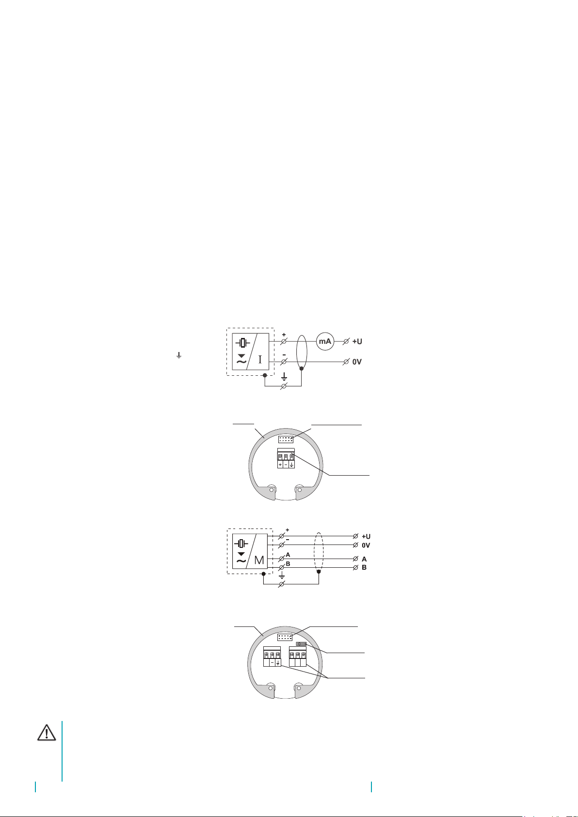
Thelevelmeterisconnectedtoconsequential(evaluating)devicewithasuitablecablewiththe
outerdiameterof6to8mmusingscrewterminalslocatedunderthedisplaymodule.Therecom-
mendedcrosssectionofcoresforthecurrentversion2x0,5÷0,75mm2 and for the version with
Modbuscommunication2x2x0,25mm2 (twistedpair,
shielded).Pluspole(+U)isconnectedtotheterminal
(+),minuspole(0V)totheterminal(-)andtheshielding
(onlyforshieldedcables)totheterminal().Commu-
nicationwiresAandBofthelineRS-485(forversion
"M"-Modbus)areconnectedtotheterminalsAandB.
Procedure to connect the cable to the level meter:
1. Unscrew the nut of the upper transparent lid.
2. Take the upper edge of the display module and
takeitoutcarefullybymildswingingup.
3. If you cannot grasp the module, you can use
a small screwdriver. Insert it as far as the seam and
usefromseveralsidestoslightlyliftthemodule.
4. Release the cable outlet and thread the stripped
supplycablein.
5. Connectthecabletothescrewterminalsaccord-
ingtothediagraminFig.17or18.Firmlytighten
theterminalsandthecableoutlet.
6. If the level meter with Modbus is involved as a
terminalforRS-485,werecommend(toavoidre-
flections ontheline)toconnect120Ωtermination
resistor. This is done by moving a small lever of
theswitchmarked120ΩtotheONposition.Onthe
levelmetersconnectedtothelineRS-485as an
intermediatedevice, the termination resistorsare
notconnected(switchremainsoff).
7. Insert the display module back into the head so
thattheconnectorisproperlyconnected.
8. Slidesiliconesealonthethreadofthelevelmeter
body,thentightenthenutoftheupperlid.Connect
thecabletoconsequentialdevice.
Fig. 16: Wiring diagram of the level meter
with current output UPS 1000 _-_-_- I
metal clip display unit connector
Terminal block
Electrical connection must be done in de-energized state!
With regard to possible occurrence of electrostatic charge on non-conductive parts of the
level meter, all level meters for explosive spaces (UPS–70Xi type) must be grounded. It
will be done using a screw placed on the head of the level meter under the cable outlet.
Fig. 17: Inside view of screw terminals of the
level meter with current output UPS 1000_-_-_-I
+ABIS
GND
ON
120
display unit connector
Terminal block
metal clip
120Ω switch
Fig. 18: Wiring diagram of the level
meter with Modbus UltraPro
1000_-_-_-M
Fig. 19: Inside view of screw terminals of the
level meter with Modbus UPS 1000_-_-_-M

10
© Levelpro, s.r.o. UltraPro-1000
The supply voltage source should be preferably realized as a stabilized power supply unit with safe
voltage from 18 to 36 V DC (18 ÷ 30 V DC for Xi version), which can be a part of the evaluation or
display device.
In case of strong electromagnetic interferences (EMI), parallel cable ducting with power lines, or
when cable length exceeds 30 m we recommended to use shielded cable.
It is also necessary to design and take measures to reduce the effects of static electricity
to a safe level in the wiring.
Installation in explosive atmospheres needs to be carried out in compliance with CSN EN
60079-14 (Electrical installations for explosive gaseous atmospheres – Part 14: Electrical
installations in dangerous areas other than mining) and possibly also in compliance with
other standards relating to the area concerned.
8 .
exaMples of
UltraPro 1000 connecTion
(input 4 ... 20 mA )
(0V) -
UPS-1000-_ _-_-I
User manual - METER PDU-4xx-P
Figure 4.7. Terminals description (relay outputs, device with current output)
Figure 4.8. Terminals description (OC-type outputs)
Figure 4.9. Connection of 2-wire current converters
11
1 2 5 6 7 8 9
GND DATA+
DATA-
RS - 485
+Uo -
+24V +5%, -10%
Imax = 100mA
10 11 12 13 14 15
R1
3 4
optional ACTIVE
current output
-+
R2
n.c. n.c. n.c.
n.c.
GND
0/1 - 5V, 0/2 - 10V
0/4-20mA
++
(optional) (optional)
Power
supply
(depending on version)
16
31
17
32
18
33
19
34
20
35
1 2 5 6 7 8 9
GND DATA+
DATA-
RS - 485
+Uo -
+24V +5%, -10%
Imax = 100mA
10 11 12 13 14 15
3 4
OC1 OC2
- + + -
OC1 ÷ OC4: Umax = 30V DC,
Imax = 30mA, Pmax = 100mW
+ -
- +
OC3
OC4
(optional)
(optional)
n.c.
n.c.
GND
0/1 - 5V, 0/2 - 10V
0/4-20mA
++
(optional)
(optional)
Power
supply
(depending on version)
16
31
17
32
18
33
19
34
20
35
5 6
24V DC
- +
+ -
+
-
+
-
internally connected
16
31
17
32
18
33
19
34
20
35
16
31
17
32
18
33
19
34
20
35
UPS-1000_ _-_-I
connectedinternally
(input 4 ... 20 mA )
8 .1 .
Wiring diagram of the level meter With current output and pdu unit
(+U) + (+U) + (0V) -
connectedinternally
User manual - METER SRP-N118
a) b)
Figure 4.2. Recommended dimensions of cable stripping
a) for big connectors (1 to 6), b) for small connectors (7 to 13, 15 to 17)
Figure 4.3. Method of connecting cables to the clamping connectors
All connections must be made while power supply is disconnected !
Figure 4.4. Terminals description (relay outputs)
9
!
+Uo -
n.c.
R1 R2
GND
0/1 - 5V
0/2 - 10V
0/4 - 20mA
+
+
GND
GND
DATA+
151617
12 11 10 9 8 713
14 1
2
3
4
5
6
DATA-
RS - 485
(option) (option)
Power supply
(depending
on version)
24V (+5%, -10%)
Imax = 100 mA
PE
n.c.
5 mm
max. 1.6 mm
6 mm
max. 2 mm
Connection of PDU-420-W is valid for rmware version 6.00 or higher. The older versions (up to version
5.99), the level meter output +U is connected to the terminal 7 and the output 0V to the terminal 10.
Levelpro TVL Series Displays

UltraPro 1000 © Levelpro, s.r.o.
11
8 .2 .
Wiring diagram of the level meter With current output
and pdu unit in versions for explosive areas
(+U) +
(0 V) –
UPS-1000-Xi-_ _-_-I
IRU-420-I
explosive
area
User manual - METER SRP-N118
a) b)
Figure 4.2. Recommended dimensions of cable stripping
a) for big connectors (1 to 6), b) for small connectors (7 to 13, 15 to 17)
Figure 4.3. Method of connecting cables to the clamping connectors
All connections must be made while power supply is disconnected !
Figure 4.4. Terminals description (relay outputs)
9
!
+ Uo -
n.c.
R1 R2
GND
0/1 - 5V
0/2 - 10V
0/4 - 20mA
+
+
GND
GND
DATA+
151617 12 11 10 9 8 71314 1
2
3
4
5
6
DATA-
RS - 485
(option) (option)
Power supply
(depending
on version)
24V (+5%, -10%)
Imax = 100 mA
PE
n.c.
5 mm
max. 1.6 mm
6 mm
max. 2 mm
PDU-420-W-230V
(input 4 ... 20 mA )
Connection of PDU-420-W is valid for rmware version 6.00 or higher. The older versions (up to
version 5.99), the terminal 9 of the IRU unit is connected to the terminal 10 of the PDU unit and the
terminal 10 of the IRU unit is connected to the terminal 11 of the PDU unit.
non-explosive
area
User manual - METER SRP-N118
a) b)
Figure 4.2. Recommended dimensions of cable stripping
a) for big connectors (1 to 6), b) for small connectors (7 to 13, 15 to 17)
Figure 4.3. Method of connecting cables to the clamping connectors
All connections must be made while power supply is disconnected !
Figure 4.4. Terminals description (relay outputs)
9
!
+Uo -
n.c.
R1 R2
GND
0/1 - 5V
0/2 - 10V
0/4 - 20mA
+
+
GND
GND
DATA+
151617 12 11 10 9 8 71314 1
2
3
4
5
6
DATA-
RS - 485
(option) (option)
Power supply
(depending
on version)
24V (+5%, -10%)
Imax = 100 mA
PE
n.c.
5 mm
max. 1.6 mm
6 mm
max. 2 mm
L
N
230 V AC

12
© Levelpro, s.r.o. UltraPro 1000
User manual - METER SRP-94
Double numeration means, that depending on device version, particular
terminal can be marked according to the top or bottom number.
Figure 4.6. Terminals description (relay outputs)
Figure 4.7. Terminals description (OC-type outputs)
11
GND DATA+
DATA-
RS - 485
+Uo -
+24V +5%, -10%
Imax = 100mA
1 2 5 6 7 8 9
10 11 12 13 14 15
3 4
31 32 33 34 35
OC1 OC2
- +
OC1 ÷ OC4: Umax = 30V DC,
Imax = 30mA, Pmax = 100mW
OC3
OC4
+ - + -
+ -
(optional) (optional) (optional)
(optional)
Power
supply
(depending on version)
n.c. n.c.
GND
0/1 - 5V, 0/2 - 10V
0/4-20mA
++
Power
supply
(depending on version)
GND DATA+
DATA-
RS - 485
+ Uo -
+24V +5%, -10%
Imax = 100mA
1 2 5 6 7 8 9
10 11 12 13 14 15
3 4
31 32 33 34 35
R1 R2 R3
R4
(optional) (optional) (optional)
(optional)
n.c. n.c.
GND
0/1 - 5V, 0/2 - 10V
0/4-20mA
++
16
31
(+U) +
(0 V) –
UPS-1000-Xi-_ _-_-I
IRU-420-I
PDU-4xx-P-230V
(input 4 ... 20 mA )
User manual - METER SRP-94
Double numeration means, that depending on device version, particular
terminal can be marked according to the top or bottom number.
Figure 4.6. Terminals description (relay outputs)
Figure 4.7. Terminals description (OC-type outputs)
11
GND DATA+
DATA-
RS - 485
+Uo -
+24V +5%, -10%
Imax = 100mA
1 2 5 6 7 8 9
10 11 12 13 14 15
3 4
31 32 33 34 35
OC1 OC2
- +
OC1 ÷ OC4: Umax = 30V DC,
Imax = 30mA, Pmax = 100mW
OC3
OC4
+ - + -
+ -
(optional) (optional) (optional)
(optional)
Power
supply
(depending on version)
n.c. n.c.
GND
0/1 - 5V, 0/2 - 10V
0/4-20mA
++
Power
supply
(depending on version)
GND DATA+
DATA-
RS - 485
+Uo -
+24V +5%, -10%
Imax = 100mA
1 2 5 6 7 8 9
10 11 12 13 14 15
3 4
31 32 33 34 35
R1 R2 R3
R4
(optional) (optional) (optional)
(optional)
n.c. n.c.
GND
0/1 - 5V, 0/2 - 10V
0/4-20mA
++
16
31
explosive
area
non-explosive
area
User manual - METER PDU-4xx-P
Figure 4.7. Terminals description (relay outputs, device with current output)
Figure 4.8. Terminals description (OC-type outputs)
Figure 4.9. Connection of 2-wire current converters
11
1 2 5 6 7 8 9
GND DATA+
DATA-
RS - 485
+Uo -
+24V +5%, -10%
Imax = 100mA
10 11 12 13 14 15
R1
3 4
optional ACTIVE
current output
-+
R2
n.c. n.c. n.c.
n.c.
GND
0/1 - 5V, 0/2 - 10V
0/4-20mA
++
(optional) (optional)
Power
supply
(depending on version)
16
31
17
32
18
33
19
34
20
35
1 2 5 6 7 8 9
GND DATA+
DATA-
RS - 485
+Uo -
+24V +5%, -10%
Imax = 100mA
10 11 12 13 14 15
3 4
OC1 OC2
- + + -
OC1 ÷ OC4: Umax = 30V DC,
Imax = 30mA, Pmax = 100mW
+ -
- +
OC3
OC4
(optional)
(optional)
n.c.
n.c.
GND
0/1 - 5V, 0/2 - 10V
0/4-20mA
++
(optional)
(optional)
Power
supply
(depending on version)
16
31
17
32
18
33
19
34
20
35
5 6 24V DC
- +
+ -
+
-
+
-
internally connected
16
31
17
32
18
33
19
34
20
35
16
31
17
32
18
33
19
34
20
35
User manual - METER SRP-N118
a) b)
Figure 4.2. Recommended dimensions of cable stripping
a) for big connectors (1 to 6), b) for small connectors (7 to 13, 15 to 17)
Figure 4.3. Method of connecting cables to the clamping connectors
All connections must be made while power supply is disconnected !
Figure 4.4. Terminals description (relay outputs)
9
!
+Uo -
n.c.
R1 R2
GND
0/1 - 5V
0/2 - 10V
0/4 - 20mA
+
+
GND
GND
DATA+
151617 12 11 10 9 8 71314 1
2
3
4
5
6
DATA-
RS - 485
(option) (option)
Power supply
(depending
on version)
24V
(+5%, -10%)
Imax = 100 mA
PE
n.c.
5 mm
max. 1.6 mm
6 mm
max. 2 mm
L
N
230 V AC

UltraPro 1000 © Levelpro, s.r.o.
13
(+U) +
(0 V) -
UPS-1000-_ _-_-I
MGU-800
(with module IUI4)
8 .3 .
Wiring diagram of the level meter With current output and mgu unit
12 13 14 18 19
AB +_
S
RS 485 - Master +24V DC
Imax=120 mA
(A) YE
(B) GN
(0V) WH
(+U) BN
Cab.Sh.
UPS-1000-_ _-_-M
(A) YE
(B) GN
(0V) WH
(+U) BN
Cab.Sh.
MGU-800
(without additional modules)
8 .4 .
Wiring diagram of the level meter With modbus / rs485 and mgu unit
8 .5 .
Wiring diagram of the level meter With modbus / rs485 and pdu unit
UPS-1000-_ _-_-M

14
© Levelpro, s.r.o. UltraPro 1000
ESC OK
www.dinel.cz
Ultrasonic Level Meter ULM-70
ESC OK
1745
TEmm
10 .
sTaTus signalizaTion
1) symbol appears in the lower left corner of the display
display function
"NO ECHO" Flashing – the level meter is not able to receive echo for a long time. Incorrect
installation of the level meter
"DEAD ZONE" Flashing – the measured level is in the "dead zone" of the level meter or the
ultrasonic converter is dirty.
"NO PASSWORD" It will appear in the item "MENU" – the level meter is protected using a pass-
word against unauthorised setting. Enter the correct password (see p. 19).
Symbol "T" 1) Flashing – "TEACHING" mode activation.
Symbol "E" 1) Flashing– correct echo receiving (of the reflected signal) from
the measured surface level.
Symbol
ESC OK
www.dinel.cz
Ultrasonic Level Meter ULM-70
ESC OK
1745
TEmm
1) Flashing – level meter is locked against unauthorized settings by
a password. You must enter the correct password to unlock it (see page 19).
Level meter locked
Ultrasonic transmitter
Upper lid nut
Cable gland
Control buttons
OLED display Label
9 .
seT-up eleMenTs
Button
•Set-upmodeaccess
•Conrmationofselectediteminthemenu
•Movethecursorintheline
•Savingofset-updata
Button
•Moveinthemenu
•Change of values
Button
•Cancelling of carried out changes
•Shiftonelevelup
Echo receiving
Units
Teaching
mode activation
Fig. 20: Full view of the level meter
ESC OK
www.dinel.cz
Ultrasonic Level Meter ULM-70
ESC OK
1745
Tmm
Display
of measured values
Set-up elements

UltraPro-1000 © Levelpro, s.r.o.
15
STARTING
Levelpro®
11 .
operaTion anD seTTing
Setthelevelmeterusing3buttonsplacedonthedisplaymodule
(seeChapterSet-upelements).After5min.ofinactivity,thelevel
meterautomaticallyreturnsbacktothemeasurementmode.Ifthe
password is active, the level meter will be also locked. The val-
uesthathavenotbeenconfirmed usingthebutton willnotbe
saved!After themeter islocked, you cannotchange the setting!
Whenyouattempttoedit,thewords"NOPASSWORD"willappear
onthedisplay.Howtounlockthelevelmeterisgivenonpage16.
After connection of the supply voltage to the level meter the
displayshowsthelogo"Levelpro"andthetext"Starting"(approx.
15s).Then,thelevelmetergoestothemeasuringmodeandthe
displayshowsthe current measured value.
MIN LEVEL and MAX LEVEL
Youcan freelydefine theminimum / maximum distance from the front surface of the level
meter(item"LEVEL"forcurrents4/20mA).The"DISPLAY"isintendedtosetthevaluedisplayed
onthedisplay.Settingtheunitsisdoneinthe"UNITS".
Ifinthebottomofthedisplayappears(whenenteringthevalues)theinscription"OUTOFLIMITS",
thevaluespecifie fortheitem"LEVEL"isoutsidethemeasuringrangeofthelevelmeter.Ifthe
inscription"SPANTOOSMALL"isshown,itmustbespecified alargerspanbetweenMinandMax
values.Formoreinformation,seechapter"Specications".
Thedecimalpointpositionoftheitem'LEVEL'isfirmly set(accordingtotheselectedunits),inthe
item"DISPLAY"itisfreelyadjustable
11 .1 .
basic configuration
Afterthefirst startofthelevelmeteritisnecessarytoperformthe
basicconfiguratio (settingofthemeasuringrange,choiceofunits
and possibly damping). The settings are accessible in the basic
menubypressing the"BASICSETTINGS".
UNITS
LEVEL: mm
DISPLAY: %
TEMPERATURE °C
MIN LEVEL
MAX LEVEL
UNITS
DAMPING
SENSITIVITY
TEACHING
MIN ACTUAL LEVEL
02870mm
OUTPUT: 04.00mA
LEVEL: 06000mm
DISPLAY: 00000%
MAX ACTUAL LEVEL
02870mm
OUTPUT: 20.00mA
LEVEL: 00250mm
DISPLAY: 00100%
ACTUAL LEVEL: Actual distance to level
OUTPUT: current 4 mA / 20 mA
LEVEL: Denition of the min / max level
DISPLAY: The value showed on the display
MIN LEVEL
MAX LEVEL
UNITS
DAMPING
SENSITIVITY
TEACHING
BASIC SETTINGS
SERVICE
DIAGNOSTIC
CLONE SETTINGS
PASSWORD
LANGUAGE
INFO

16
© Levelpro, s.r.o. UltraPro-1000
UNITS
LEVEL: mm
DISPLAY: %
TEMPERATURE °C
DAMPING
05
UNITS
Levelmetercanprocessandconvertalargenumberofdifferentphysical values. The setting is
doneintheitem"UNITS".
LEVEL: Unit selection (mm, cm, m, in, ft)
DISPLAY: The unit showed on the display
(%, mm, cm, m, in, ft, l, hl, m3, gal, bbl, mA)
TEMPERATURE: Temperature unit (°C, °F)
DAMPING
Settingthe response time of the measurements. Thefunctionisusefulforsuppressinglevelfl c-
tuations,wavesandrapidchangesofthelevel.The reaction time will depend on the exponential
function.Dampingwithadefined delayinsecondsrepresentsthetimewhenexponentialreaches
2/3ofitsmaximumvalue.
The damping time can be set in the interval
from 0 to 99 s.
1. To enter to the menu press thesamebuttontoselect"BASICSETTINGS".Then,using
and select"UNITS".
2. Nowthemenuitem"UNITS"isshown. Bypressingthe and buttonmakethesettingsof
individual items.
3. Bypressing buttonsavethedata.Bynextpressesofthebutton leave the menu. The
level meter returns to measurement mode.
1. To enter to the menu press thesamebuttontoselect"BASICSETTINGS".Then,using
and select"DAMPING".
2. Nowthemenuitem"DAMPING"isshown. Bypressingthe and buttonmakethesettings
of individual items.
3. Bypressing buttonsavethedata.Bynextpressesofthebutton leave the menu. The
level meter returns to measurement mode.
1. To enter to the menu press thesamebuttontoselect"BASICSETTINGS". Then,using
and select "MINLEVEL"or"MAXLEVEL".
2. Nowitisshowntheitem"MINLEVEL"("MAXLEVEL").Bypressing and set the output cur-
rent"OUTPUT",thedistanceforthedenedcurrent"LEVEL"thevalueonthedisplay "DISPLAY".
3. Bypressing buttonsavethedata.Bynextpressesofthebutton leave the menu. The
level meter returns to measurement mode.
MIN LEVEL
MAX LEVEL
UNITS
DAMPING
SENSITIVITY
TEACHING
MIN LEVEL
MAX LEVEL
UNITS
DAMPING
SENSITIVITY
TEACHING

UltraPro 1000 © Levelpro, s.r.o.
17
You can set the sensitivity in three degrees:
LOW – MEDIUM – HIGH.
SENSITIVITY
Thesettingisdenedinthreestepsofthelevelmetersensitivity.
"LOW" – Low sensitivity in case of surrounding interferences affecting the measurement.
"MEDIUM" – Medium sensitivity (suitable for most applications).
"HIGH" – Enhanced sensitivity for measured mediums partly absorbing the ultrasonic signal (bulk solids, foams)
If there are no above obstacles in the tank, it is
not necessary to start this mode.
TEACHING
The mode serves for suppressing false reectionsresultingfromreectionoftheultrasonic
signalfromroughnessesonwallsofthetank,variouspartitions,mixersorotherobstacles.The
sensorstartingthismodedetectsfalsereectionsandsavetheminthememory.Thenthesefalse
reectionswillnotaffectthesubsequentmeasurement(theyaremasked).
Before starting the mode it is necessary to empty the tank as much as possible (prefer-
ably completely).
1. To enter to the menu press thesamebuttontoselect"SERVICE".Then,using and
select"TEACHING".
2. Nowitisshowntheitem"TEACHING".Bypressing setthevalue"LEVELDISTANCE"(dis-
tancetothelevel)–supposeddistancefromthefaceofthesensortothemediumlevel.Ifthe
distancetothelevelisnotpreciselyknown,enteravalue
lower(inthetolerancefieldas
showninFig.19).
3. Afterenteringthe"SETLEVELDISTANCE"bypressing buttonthesystemstarts"teaching"
(falsereectionmapping).Duringthemapping,thedisplayshowsfl shingsign"RUNNING".
4. Themappingoffalseechoescanbecompletedwhenyouseetheinscription"PressOKtostop"
andyoupress .
5.
Theprocedureiscompletelyfinishedwhenyoucanseetheinscription"DONE".Itisthen
possibletoexitthemenubyrepeatedpressingthebutton .
SENSITIVITY
MEDIUM
TEACHING
SET LEVEL DISTANCE:
06000 mm
START
MIN LEVEL
MAX LEVEL
UNITS
DAMPING
SENSITIVITY
TEACHING
MIN LEVEL
MAX LEVEL
UNITS
DAMPING
SENSITIVITY
TEACHING
TEACHING
SET LEVEL DISTANCE:
06000 mm
RUNNING
TEACHING
SET LEVEL DISTANCE:
06000 mm
DONE
PRESS ESC TO EXIT
The mode "TEACHING" will stop automati-
cally after ca. 1000 measurements.
TEACHING
SET LEVEL DISTANCE:
06000 mm
RUNNING
PRESS OK TO STOP
If during the scanning of the tank in the bottom of the display appears
the dialog "press OK to stop" (see gure) the level meter already found
no further obstacles and "TEACHING" mode may be terminated. If it is
not terminated, the level meter is still ready for the possible presence
of obstacles (e.g. paddles of the agitator). Once it registers a further
obstacle, the dialogue disappears and the obstacle is erased. This
process may be repeated up to 1000 cycles. After this the "TEACHING" mode is automatically stopped.

18
© Levelpro, s.r.o. UltraPro 1000
Incaseofinstalledmixers,itisnecessary to position
the mixers under the level meter (direct the mixer
bladetotheultrasonicsignalbeam).
Note:Iftherearesignicantobstaclesintheupper
halfofthetank,multiple false reections can
occurespeciallyinclosedtanks.Insuchcases
itisnecessarytoreducethelevelinthetankas
muchsepossibletocorrectlymaskthesepossible
multiplefalsereections.
1/2 of Tank
Obstacles
Tolerance zone for
"LEVEL DISTANCE" value
MEDIUM TEMPERATURE
The level meter is equipped with automatic temperature compensation. If for instance inside
the tank there is a difference of 10°C between the temperature of the measured material (me-
dium) and the temperature at the mounting site of the level meter (see the mode "DIAGNOS-
TICS,page 20), the measuringaccuracywillbereducedbyaround1% of thesetrange.Ifthis
functionisactivated thistemperaturedifferencecanbecompensated.
MEDIUM TEMPERATURE
FAILURE MODE
HART
FACTORY DEFAULT
RESET
MEDIUM TEMPERATURE
YES
+20°C
Inactive compensation (initial state), the
word "NO" appears on the display.
See the "UNITS" menu for temperature unit
selection (°C or °F).
Afterstartofthezone temperature compensationmodeitisnecessarytosetthetemperature
of the surface of the medium. The level sensor then calculates the average value from the
medium temperature and the temperature at the installation place of the level meter.
Level Distance
NO ECHO: Current in case of echo loss
DEAD ZONE: Dead zone current
The values can be set in three steps:
3.75 mA, 22 mA and LAST (last measured data).
FAILURE MODE
It defines the output current of the level sensor when the measured medium level is in the dead
zone ("DEADZONE")oroutsidethemeasurementrangeincaseofecholoss("NOECHO").
FAILURE MODE
NO ECHO: 3.75 mA
DEAD ZONE: 22 mA
11 .2 .
services settings
In the supplemented configuration, you can set parameters of
sensitivity, mapping of false reflections, temperature difference
compensation, behaviour in case of fault conditions or HART®
communication.Here,youcansetthesensorintotheinitialstate
orresetitaswell.Thesettingsareaccessibleinthebasicmenu
undertheitem"SERVICE".
BASIC SETTINGS
SERVICE
DIAGNOSTIC
CLONE SETTINGS
PASSWORD
INFO
MEDIUM TEMPERATURE
FAILURE MODE
HART
FACTORY DEFAULT
RESET
Fig. 21: Level distance zone

Ultrapro 1000 © Levelpro, s.r.o.
19
HART
HART® mode(pointtopoint,multidrop)andmultidropmodeaddress setting.Upto15unitscanbe
connectedtoonetwo-wiredcableinthemultidropmode.
In case of the address "00", the point to point
mode is enabled. The range from "01" to "15" is
reserved for addresses in the multidrop mode.
After you press the button "RUNNING"
will be displayed for about 3 sec. After the
initial values are set, "DONE" will be appear
on the display.
FACTORY DEFAULT
To reset the initial values ofthelevelmetersetbythemanufacturer,pressthebutton (see the
Factorydefaulttable,p.28).
RESET
Complete restartofthelevelmeter.Thesameeffecthasalsoashort-timeinterruptionofthesupply
voltage.Toenabletheresetting,pressthebutton
.
FACTORY DEFAULT
ARE YOU SURE?
FACTORY DEFAULT
RUNNING
FACTORY DEFAULT
DONE
PRESS ESC TO EXIT
RESET
ARE YOU SURE?
During the restart process, "RUNNING" will
be displayed. Then the level meter will be
automatically turned off and on.
MODBUS
ThisitemispartofamenuwithModbusoutputlevelmeterUltraPro 1000_-_-_-M.Modbus
modeisintendedforthesettingsofthelevelModbusaddresses,baudrateandparitysettings.
MODBUS
ADDRESS: 001
BAUD RATE: 9600
FORMAT: 8N1
ADDRESS: 1 to 247 (default 1)
BAUD RATE: 4800, 9600, 19200
(default 9600)
FORMAT : 8N1, 8O1, 8E1, 8N2 (default 8N1)
data:
parita:N – non parity
O – odd parity
E – even parity
8 – number of bits
FORMAT: number of stop bits:1
2
MEDIUM TEMPERATURE
FAILURE MODE
HART
FACTORY DEFAULT
RESET
HART
00
POLLING ADDRESS
MEDIUM TEMPERATURE
FAILURE MODE
MODBUS
FACTORY DEFAULT
RESET
MEDIUM TEMPERATURE
FAILURE MODE
MODBUS
FACTORY DEFAULT
RESET
MEDIUM TEMPERATURE
FAILURE MODE
MODBUS
FACTORY DEFAULT
RESET
Table of contents
Other Level Pro Measuring Instrument manuals