Level Pro VIEWSONIC2 Series User manual

R
Manual
VIEWSONIC2 SERIES
VIEWSONIC2 Series
Operating Instructions
set
alarm
TANK LEVEL
TIME
14.2
2 1.
2 1
:43
7
9
100%
ON
10%
FEET
+/max/min
-/tank
C

1) Open the battery door, remove the battery box;
2) Insert 6 x AAA 1.5V alkaline batteries into the battery box, observing the correct polarity. Then put back the battery
box according to the marking direction.
The following picture illustrates transmitter installation:
Please pay attention to the following issues in installation:
1) The distance between transmitter bottom and highest water surface must be 0.5m (1.64ft) or more.
2) The maximum depth the unit can measure is 15m (49.2ft).
3) Observe the balance bubble on the sensor to ensure it is installed at a level horizontal position.
Figure 1
Figure 2
Figure 3
R
Manual
VIEWSONIC2 SERIES
Range
Span
12 3 4
1.1. Insert Battery
1.2. Set Up
1.3 Examples of Wrong Installation

set
alarm
+/max/min
-/tank
TANK LEVEL
100
EMPTY
M
%
10
%
1) The sensor is not installed at a level horizontal position.
2) The sensor is too close to the Tank wall.
3) There are solid objects in the tank.
4) The transmitter bottom is dipped in the water (or other liquids in tank)
Note: Even though it works fine in occasional water splash or dew, this product is not completely water proof in heavy
rain. It is highly recommended that a cover be installed above the unit.
First, insert the batteries into the wireless solar transmitter (6 x AAA) and then insert batteries immediately into the LCD
display base unit (2 x AA). Once the batteries are in place, all segments of the LCD will light up briefly.
R
Manual
VIEWSONIC2 SERIES
AAA Batteries : 6pcs
Transmitter
This Key has
no Function
Key to
Increase Value in
Setup or Check
max/min Record
LCD Display Back LCD Display Front
AA Batteries : 2pcs
set
alarm
+/max/min
-/tank
TANK
F
TIME
PM
AL
LEVEL
100
EMPTY
HI
AL
L
O
AL
8
8
8 88
8
88
8
M
FEET
ON
MAX
MIN
FULL
%
10
%
+/max/min
-/tank
Key to
Decrease
Value in Setup or Switch
Between Temperature
and Depth Value
set
Key to Set
up Parameters
alarm
Key to
View and Set
up Time and
Depth Alarm
1.4 Initial Setup

Figure 6
The following illustration shows a normal LCD display for description purposes only.
1. Value Display Area
2. Tank Temperature and Water Level
Icon
3. Liquid Level Units
4. Tank Temperature Unit (ºC/ºF)
5. Sensor Battery Indicator
6. Alarm Activation Icon
7. Min-Max Indicator
8. Empty Alert Icon
9. RF Signal Indicaton
1. Insert Batteries
2. LCD display Beeps after 3 seconds. "0.00" is Displayed
3.1 Program Sensor Range
R
Manual
VIEWSONIC2 SERIES
TANK
F
TIME
PM
AL
LEVEL
100
EMPTY
HI
AL
L
O
AL
8
8
8 88
8
88
8
M
FEET
ON
MAX
MIN
FULL
%
10
%
1
16
2 3 4 5 6 7
8
9
10
11
15
14
13
12
Figure 7
Figure 8
Press Key or Key to Set Range Depth.
Press the Key to Access the Air Gap setting (Figure 8).
set
alarm
+/max/min
-/tank
TANK LEVEL
100
EMPTY
M
%
10
%
set
alarm
+/max/min
-/tank
TANK LEVEL
100
EMPTY
M
%
10
%
+/max/min
set
alarm
+/max/min
-/tank
TANK LEVEL
100
EMPTY
M
%
10
%
+/max/min
3. PROGRAMMING
2. OVERVIEW
Range
Bottom of Sensor
set
+/max/min -/tank
10. High-Low Alarm Indication
11. Time Alarm Indication

set
alarm
+/max/min
-/tank
TANK LEVEL
100
M
FULL
%
10
%
set
alarm
+/max/min
-/tank
TANK LEVEL
100
M
FULL
%
10
%
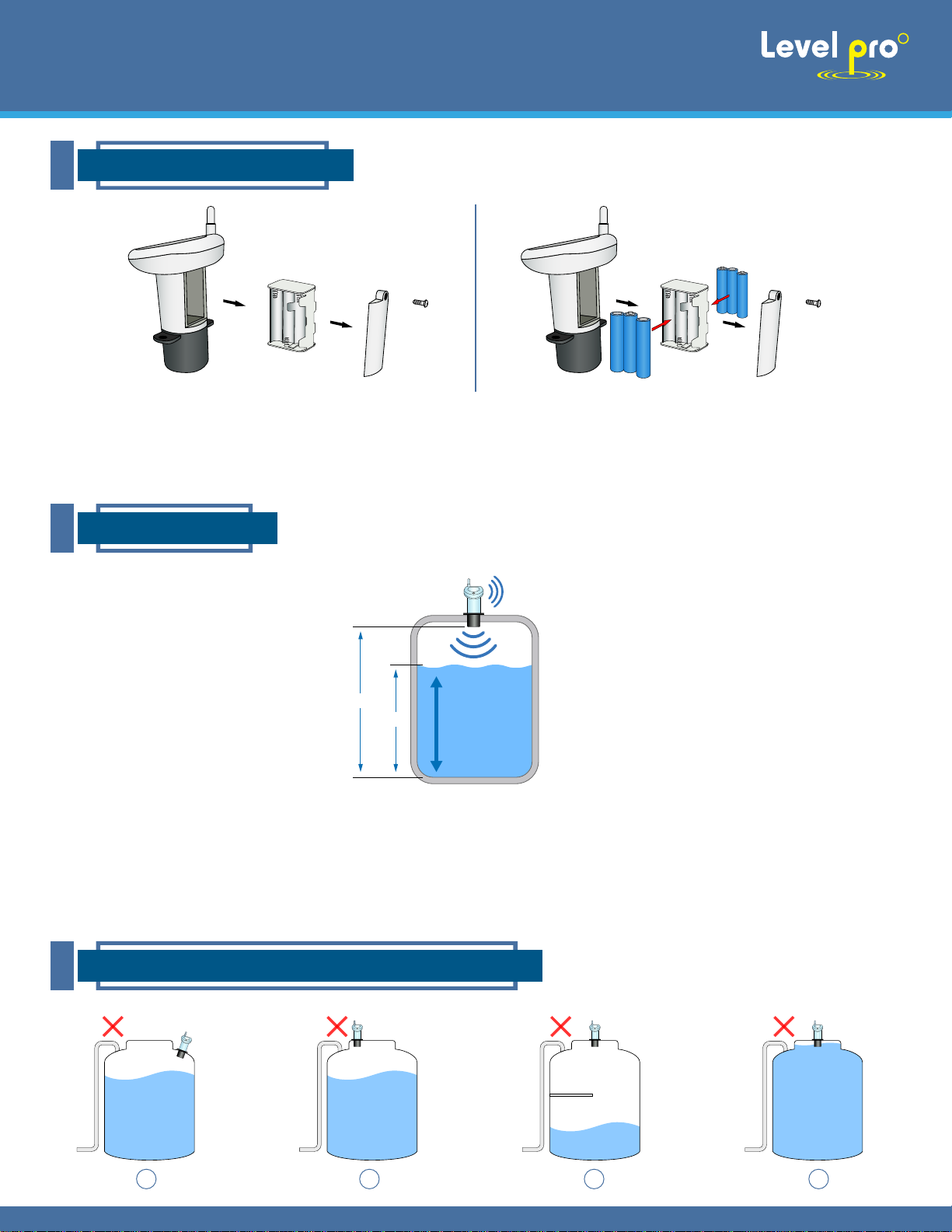
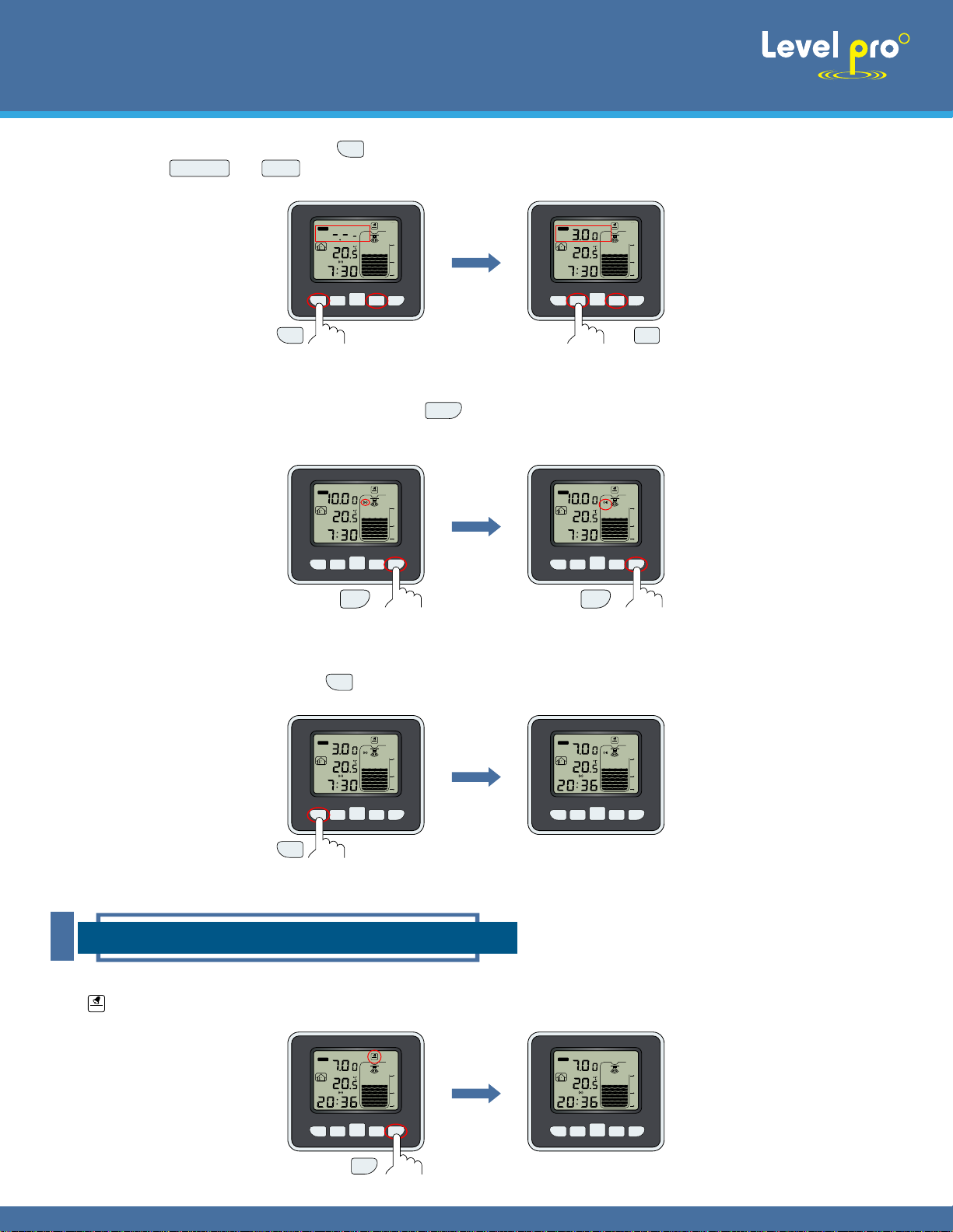
The Range is defined as the distance from the bottom of the tank transmitter to bottom of your tank. Minimum Range
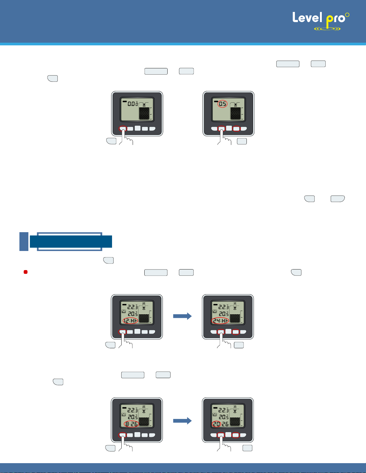
18" Maximum Range 49 ft. Display of "0.00" and full tank icon flashes (Figure 9). Press or key to
increase or decrease air gap. Long press or key to increase or decrease air gap at greater step.
Press the key to exit depth setting
NOTE: Air Gap (see H1 in sketch of 2.2) is defined as the distance from the bottom of the tank transmitter to the
maximum fluid level of tank. The range is: 0.5M(min) - 15.0M(max) or 1.64" (min)-49.2" (max).
If there’s no key operation in depth setting mode for longer than 15s the unit will switch to normal display mode
automatically. (There will be measurement errors if the tank depth and air gap are not set correctly).
In normal display mode press key for 3 seconds to enter SET mode (Figure 10).
HOUR: Hour value will flash. Press or key to increase or decrease hour value. When hour value
is set press key to set minute value (Figure 11).
12/24H: 12Hr or 24Hr will flash. Press or key to select 12H or 24H. Press key to move to
hour setting.
R
Manual
VIEWSONIC2 SERIES
Figure 9
set
+/max/min
Figure 10
Press SET key for 3 seconds
+/max/min
set
alarm
+/max/min
-/tank
TANK
F
TIME
100
M
ON
%
10
%
FULL
set
alarm
+/max/min
-/tank
TANK
F
TIME
100
M
ON
%
10
%
FULL
set
set
set
set
+/max/min -/tank
+/max/min -/tank
+/max/min -/tank
+/max/min -/tank
Figure 11
set
set
alarm
+/max/min
-/tank
TANK
F
TIME
100
M
ON
%
10
%
FULL
PM
AL
+/max/min
set
alarm
+/max/min
-/tank
TANK
F
TIME
100
M
ON
%
10
%
FULL
PM
AL
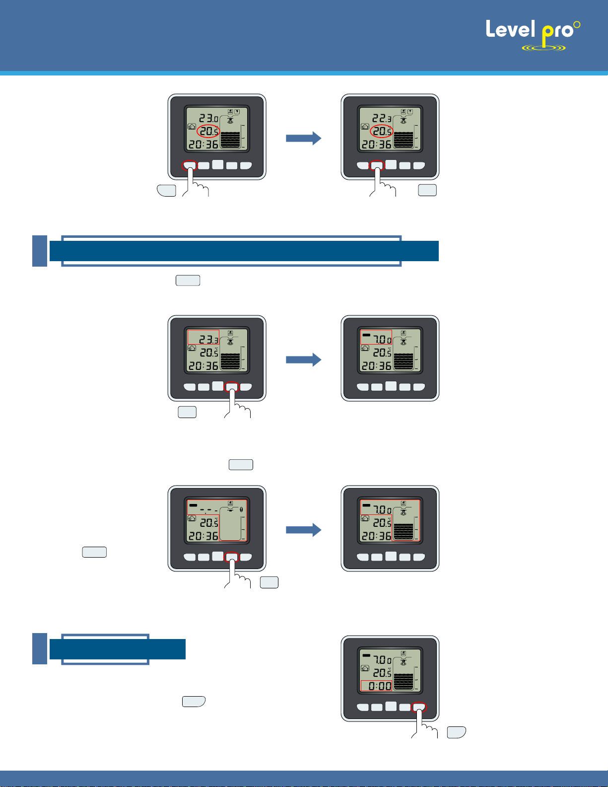
If you miss this step, tank depth and air gap can be set later. In normal operation mode, press and hold and
set
alarm
keys at the same time for 5 seconds to set Tank Depth and Air Gap values. The setting steps are the same as
described above.
3.2 Set Time
set

MINUTE: Minute value will flash. Press or key to increase or decrease minute value. When minute
value is set press key to set temperature unit (Figure 12).
Temperature unit will flash. Press or key to select temperature unit of ºC or ºF. After temperature unit
is set press key to set tank level unit (Figure 13).
Tank level unit will flash. Press or key to select water level unit of meters or feet. After tank level unit is
set press key to exit (Figure 14).
R
Manual
VIEWSONIC2 SERIES
3.3 Set Temperature Unit
3.4 Set Tank Level Unit
set
+/max/min -/tank
set
set
+/max/min -/tank
+/max/min -/tank
set
alarm
+/max/min
-/tank
TANK
F
TIME
PM
AL
LEVEL
100
EMPTY
HI
AL
L
O
AL
M
FEET
ON
MAX
MIN
%
10
%
FULL
set
alarm
+/max/min
-/tank
TANK
F
TIME
PM
AL
LEVEL
100
EMPTY
HI
AL
L
O
AL
M
FEET
ON
MAX
MIN
%
10
%
FULL
Figure 12
set
set
alarm
+/max/min
-/tank
TANK
F
TIME
100
M
ON
%
10
%
FULL
PM
AL
set
alarm
+/max/min
-/tank
TANK
F
TIME
100
M
ON
%
10
%
FULL
PM
AL
+/max/min
Figure 13
set
+/max/min
set
alarm
+/max/min
-/tank
TANK
F
TIME
PM
AL
LEVEL
100
EMPTY
HI
AL
L
O
AL
M
FEET
ON
MAX
MIN
%
10
%
FULL
set
alarm
+/max/min
-/tank
TANK
F
TIME
PM
AL
LEVEL
100
EMPTY
HI
AL
L
O
AL
M
FEET
ON
MAX
MIN
%
10
%
FULL
Figure 14
set
+/max/min

Press key again to check the min value of indoor temperature and tank level or tank temperature (Figure 16).
Press key again to exit (Figure 17).
In the MIN/MAX mode press key, min or max icon and value will flash. Press the key once, the
displayed minimum or maximum record will be reset to current value. Press key to reset the next minimum or
maximum record (Figure 18).
R
Manual
VIEWSONIC2 SERIES
Figure 15
In normal display mode press key once to check the max value of indoor temperature and tank level or tank
temperature (Figure 15).
3.5 Check and Reset MIN/MAX Value
+/max/min
set
alarm
+/max/min
-/tank
TANK
F
TIME
PM
AL
LEVEL
100
EMPTY
HI
AL
L
O
AL
M
FEET
ON
MAX
MIN
%
10
%
FULL
set
alarm
+/max/min
-/tank
TANK
F
TIME
PM
AL
LEVEL
100
EMPTY
HI
AL
L
O
AL
M
FEET
ON
MAX
MIN
%
10
%
FULL
set
alarm
+/max/min
-/tank
TANK
F
TIME
PM
AL
LEVEL
100
EMPTY
HI
AL
L
O
AL
M
FEET
ON
MAX
MIN
%
10
%
FULL
set
+/max/min
Figure 17
+/max/min
+/max/min
+/max/min
+/max/min
Figure 16
+/max/min
set
alarm
+/max/min
-/tank
TANK
F
TIME
PM
AL
LEVEL
100
EMPTY
HI
AL
L
O
AL
M
FEET
ON
MAX
MIN
%
10
%
FULL
+/max/min
set
alarm
+/max/min
-/tank
TANK
F
TIME
PM
AL
LEVEL
100
EMPTY
HI
AL
L
O
AL
M
FEET
ON
MAX
MIN
%
10
%
FULL
set
alarm
+/max/min
-/tank
TANK
F
TIME
PM
AL
LEVEL
100
EMPTY
HI
AL
L
O
AL
M
FEET
ON
MAX
MIN
%
10
%
FULL
set
set

SET TIME ALARM
key to switch from tank level display to tank temperature display or switch from
tank temperature display to tank level display (Figure 19).
When transmission signal is lost press the key for 5 seconds to re-connect with transmitter (Figure 20).
In normal display mode press key. Previously set
time alarm will display (Figure 21).
R
Manual
VIEWSONIC2 SERIES
Figure 18
Figure 20
Press the key for 5
seconds
3.7 Alarm
3.6 Tank Level and Tank Temperature Switch
set
alarm
+/max/min
-/tank
TANK
F
TIME
PM
AL
LEVEL
100
EMPTY
HI
AL
L
O
AL
M
FEET
ON
MAX
MIN
%
10
%
FULL
set
alarm
+/max/min
-/tank
TANK
F
TIME
PM
AL
LEVEL
100
EMPTY
HI
AL
L
O
AL
M
FEET
ON
MAX
MIN
%
10
%
FULL
set
+/max/min
Figure 19
set
alarm
+/max/min
-/tank
TANK
F
TIME
PM
AL
LEVEL
100
EMPTY
HI
AL
L
O
AL
M
FEET
ON
MAX
MIN
%
10
%
FULL
set
alarm
+/max/min
-/tank
TANK
F
TIME
PM
AL
LEVEL
100
EMPTY
HI
AL
L
O
AL
M
FEET
ON
MAX
MIN
%
10
%
FULL
-/tank
set
alarm
+/max/min
-/tank
TANK
F
TIME
PM
AL
LEVEL
100
EMPTY
HI
AL
L
O
AL
M
FEET
ON
MAX
MIN
%
10
%
FULL
set
alarm
+/max/min
-/tank
TANK
F
TIME
PM
AL
LEVEL
100
EMPTY
HI
AL
L
O
AL
M
FEET
ON
MAX
MIN
%
10
%
FULL
-/tank
set
alarm
+/max/min
-/tank
TANK
F
TIME
PM
AL
LEVEL
100
EMPTY
HI
AL
L
O
AL
M
FEET
ON
MAX
MIN
%
10
%
FULL
Figure 21
alarm
In normal display mode,press
-/tank
-/tank
-/tank
alarm

After alarm hour is set press key to set alarm minute. Press or key to increase or decrease
alarm minute (Figure 23).
key to enable or disable time alarm. When time alarm is enabled the
icon is visible. When time alarm is disabled the icon is invisible. Press key to confirm time alarm setting and start
to set level high or low alarm (Figure 24).
or key to increase
After finishing the time alarm setting,the set tank level alarm will flash. Press
decrease high alarm value (Figure 25).
R
Manual
VIEWSONIC2 SERIES
Press key 3 seconds to set alarm hour. Alarm hour will flash. Press or key to increase or
decrease alarm hour (Figure 22).
Figure 24
Figure 22
set
alarm
+/max/min
-/tank
TANK
F
TIME
PM
AL
LEVEL
100
EMPTY
HI
AL
L
O
AL
M
FEET
ON
MAX
MIN
%
10
%
FULL
+/max/min
set
alarm
+/max/min
-/tank
TANK
F
TIME
PM
AL
LEVEL
100
EMPTY
HI
AL
L
O
AL
M
FEET
ON
MAX
MIN
%
10
%
FULL
set
Figure 23
set
alarm
+/max/min
-/tank
TANK
F
TIME
PM
AL
LEVEL
100
EMPTY
HI
AL
L
O
AL
M
FEET
ON
MAX
MIN
%
10
%
FULL
+/max/min
set
alarm
+/max/min
-/tank
TANK
F
TIME
PM
AL
LEVEL
100
EMPTY
HI
AL
L
O
AL
M
FEET
ON
MAX
MIN
%
10
%
FULL
set
Figure 25
set
alarm
+/max/min
-/tank
TANK
F
TIME
PM
AL
LEVEL
100
EMPTY
HI
AL
L
O
AL
M
FEET
ON
MAX
MIN
%
10
%
FULL
+/max/min
set
alarm
+/max/min
-/tank
TANK
F
TIME
PM
AL
LEVEL
100
EMPTY
HI
AL
L
O
AL
M
FEET
ON
MAX
MIN
%
10
%
FULL
set
set
alarm
+/max/min
-/tank
TANK
F
TIME
PM
AL
LEVEL
100
EMPTY
HI
AL
L
O
AL
M
FEET
ON
MAX
MIN
%
10
%
FULL
alarm
set
set
+/max/min -/tank
set
+/max/min -/tank
+/max/min -/tank
During alarm hour or minute flashing press
Set Tank Level High and Low Alarm
alarm

After tank level high alarm is set press
key to set tank level low alarm. The previously set tank level low alarm value
will flash. Press or key to increase or decrease low alarm value (Figure 26).
key to enable or disable water level alarm. When high or low
alarm is enabled the icon is visible. When high or low alarm is disabled the icon is invisible (Figure 27).
In default setting the alarm buzzer is enabled. To disable the alarm buzzer press ALARM key for 5 seconds. The alarm
icon will disappear. Press ALARM key 5 seconds again to enable alarm buzzer. The alarm icon will appear (Figure
29).
After tank level low alarm is set press key to exit (Figure 28).
R
Manual
VIEWSONIC2 SERIES
Figure 26
set
alarm
+/max/min
-/tank
TANK
F
TIME
PM
AL
LEVEL
100
EMPTY
HI
AL
L
O
AL
M
FEET
ON
MAX
MIN
%
10
%
FULL
+/max/min
set
alarm
+/max/min
-/tank
TANK
F
TIME
PM
AL
LEVEL
100
EMPTY
HI
AL
L
O
AL
M
FEET
ON
MAX
MIN
%
10
%
FULL
set
Figure 27
set
alarm
+/max/min
-/tank
TANK
F
TIME
PM
AL
LEVEL
100
EMPTY
HI
AL
L
O
AL
M
FEET
ON
MAX
MIN
%
10
%
FULL
set
alarm
+/max/min
-/tank
TANK
F
TIME
PM
AL
LEVEL
100
EMPTY
HI
AL
L
O
AL
M
FEET
ON
MAX
MIN
%
10
%
FULL
set
set
+/max/min -/tank
alarm
alarm
alarm
Figure 28
set
alarm
+/max/min
-/tank
TANK
F
TIME
PM
AL
LEVEL
100
EMPTY
HI
AL
L
O
AL
M
FEET
ON
MAX
MIN
%
10
%
FULL
set
alarm
+/max/min
-/tank
TANK
F
TIME
PM
AL
LEVEL
100
EMPTY
HI
AL
L
O
AL
M
FEET
ON
MAX
MIN
%
10
%
FULL
Enable or Disable Alarm Buzzer
set
Figure 28
set
alarm
+/max/min
-/tank
TANK
F
TIME
PM
AL
LEVEL
100
EMPTY
M
FEET
ON
MAX
MIN
%
10
%
FULL
set
alarm
+/max/min
-/tank
TANK
F
TIME
PM
AL
LEVEL
100
EMPTY
HI
AL
L
O
AL
M
FEET
ON
MAX
MIN
%
10
%
FULL
ON
While the high or low alarm value is flashing,press alarm

When water level is less than 20% of tank depth,the icon
will display (Figure 30).
1. Time: 0:00-23:59 (default: 0:00)
2. 12HR/24HR format: (default: 24HR)
3. Temperature unit: ºC/ºF (default: ºC)
4. Water level/meter/feet (default: m)
5. TANK LEVEL/TANK TEMP display: (default: TANK TEMP)
6. Alarm set: 0:00-23:59 (default: 12:00, disable)
7. Water level HI-alarm: 0.15m (0 feet -49.2 feet) (default: 10m, OFF)
8. Water level LO-alarm: 0.15m (0 feet -49.2 feet) (default: 2m, OFF)
Transmission Distance: max.100 metres (in open space)
Frequency: 433MHz
Indoor temperature range: 0 to -50ºC,
Resolution: 1ºC,
Accurate: +/-1ºC,
Tank temp measure range: -40 to -60ºC,
Resolution: 1ºC,
Accurate: +/-1ºC,
Water level measure range: 0 to 15m,
Resolution: 0.01m,
Accurate: +/-0.03m
Alarm duration: 120 sec
R
Manual
VIEWSONIC2 SERIES
Figure 30
set
alarm
+/max/min
-/tank
TANK
F
TIME
PM
AL
LEVEL
100
EMPTY
HI
AL
L
O
AL
M
FEET
ON
MAX
MIN
%
10
%
FULL
EMPTY
Empty Alert
4. DEFAULT VALUE
5. SPECIFICATIONS

6. Faults and Handling
Faults Handling
Causes
Inspect power linePower supply is not well connected.Level meter does not work.
1. Inspect power line
2. Inspect the wiring and connect it
again.
3. Maintain it in the factory.
1. Power supply is not well connected.
2. Wiring between LCD and main
board falls off or comes loose.
3. The LCD is damaged.
Level meter does not display data.
1. Replace the level meter with a level
meter with greater measuring range.
2. The meter will restore the normal
measurement automatically after the
measured medium gets back to calm.
3. Check surrounding environment
and realize good electromagnetic
shielding. Do not share one power
supply with frequency converter and
motor, and make it grounded reliably.
4. Reinstall probe and make it
perpendicular to liquid surface.
5. Select an appropriate position for
installation and prevent an interfering
object.
6. Raise the installation position of
probe.
7. Check whether the medium is
powder. If so, consult the
manufacturer.
1. The measured area is beyond the
measuring range of level meter.
2. The measured medium has strong
disturbance, vibration or heavy dust.
3. There are strong interference
sources around such as frequency
converter and motor.
4. The probe is not aligned to the
measured surface.
5. There are redundant objects in the
measured space, such as support
rodsand feed openings.
6. The liquid level is in a blind area.
7. The measured medium is soft
powder or there is foam on liquid
surface.
Level meter works but there is no
change of trumpet icon on ( ) the
LC,which means that the system
is in a loststate.
R
Manual
VIEWSONIC2 SERIES
Range
100%
Measurement
Full
Configuration
Location
20 mA
4 mA 0%
Span
Table of contents
Other Level Pro Measuring Instrument manuals
Popular Measuring Instrument manuals by other brands

Endress+Hauser
Endress+Hauser Prosonic S FMU90 operating instructions

Wise
Wise SMT3000 manual

General
General MMD5NP user manual

Test Products International
Test Products International Vib Meter 9085 user guide

RD Instruments
RD Instruments WorkHorse user guide

Carrel & Carrel
Carrel & Carrel C400 Series quick start guide