10
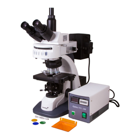
EN Levenhuk MED PRO 600 Fluo Microscope
Microscope description and operation
Application
The microscope is designed for diagnostic testing, including by immunouorescence method, in clinical, microbiological,
pathoanatomical, and other laboratories in medical institutions. Besides, it may also be used in veterinary science, crop
growing, bioengineering, pharmaceutical industry, for expertise in the sphere of criminalistics, state epidemiological
surveillance, environmental protection. The microscope is used to study stained and unstained slides in the form of smears and
microsections in transmitted light.
In the luminescence light, the microscope makes it possible to detect dangerous bacterial and virus infections when observing
objects stained by Auramine, Acridine orange, FITC etc.
Being properly operated, the microscope is safe for health, life, property of the consumer and for the environment. The
microscope stand is of anti-vibration design. The microscope is made to operate at ambient air temperature from +10 to +35°С
(50 to 95°F) and relative humidity of 80% max. The oil-immersion objective lens shall be operated indoors at ambient air
temperature from +15 to +25°С (59 to 77°F).
Microscope design and operation principle
TO PREVENT MICROSCOPE BREAKDOWN, BEFORE STUDIES, CAREFULLY REVIEW THE RULES OF HANDLING AND
PROCEDURE OF WORKING WITH THE MICROSCOPE SPECIFIED IN THIS OPERATION MANUAL.
Fluorescent microscope operating principle is based on using a phenomenon of uorescence (luminescence) of observed objects
caused by rays of light having a specic spectrum. To excite uorescence, objects are illuminated from the top through the
objective lens, with a mercury-led lamp used as a source of such light. The luminous ux required to excite uorescence is
separated from the total radiation of the mercury-lled lamp with lters, conventionally referred to as the excitation lters.
To guide the luminous ux to the objective, a beam splitter with a special interference coating is used that mostly reects
excitation light and transmits object uorescence light. The excitation lter, the beam splitter and the cut-o lter (used
to absorb the residual excitation radiation) are combined in a single beam splitting unit. A kit of ve beam splitting units is
mounted on a turret having a free socket for operating in transmitted light.
The optic system enabling object study in uorescence light is made in the form of a detachable illuminator installed on the
microscope stand. The microscope stand enables observation of objects illuminated with transmitted light.
Description and operation of components
Microscope stand
The microscope stand (g. 1, 12) has ergonomic and stable shape, and is made of metal.
There is a double-stage focusing mechanism for vertical movement of the bracket (g. 2, 3) with a coordinate stage (g. 2, 10)
and a revolving nosepiece for objective lens xation (g. 2, 7) on the stand. A uorescent illuminator (g. 2, 15) is installed on
top of the stand and is xed with a screw (g. 1, 28). The microscope stand base contains the transmitted light illumination
system and halogen lamp power source of 12V/30W. There is a socket for connection of a power cable on the rear surface of the
base on the left.
The power source is built into the microscope stand base. Power on/o button (g. 1, 18) energizes the halogen lamp installed
in the ashlight (g. 1, 13). Power is o in "O" position. Halogen lamp lament is adjusted by a knob (g. 1, 17).
There is an iris eld diaphragm, whose opening is adjusted by a ring (g. 1, 23), located on the upper surface of the microscope
base under the condenser (g. 1, 22). A decorative base (g. 2, 11) is put on the microscope stand base.
Revolving nosepiece
A six-position revolving nosepiece provides for objective lens (g. 2, 7) setting into working parfocal position. The revolving
nosepiece is inclined towards the microscope stand to provide space for installation and replacement of the examined slides.
Objective lenses are replaced by rotation of a corrugated ring (g. 1, 27) of the revolving nosepiece to the xed position.
Focusing mechanism
The focusing mechanism is designed for vertical displacement of the stage (g. 2, 10) when the microscope is focused for sharp
object image. The range of stage movement along height is 25mm. Vertical displacement of the stage is performed by coaxial
knobs (g. 2, 12 and 13) located on the left side of the microscope stand. The ne focusing mechanism knob (g. 2, 12) has a
scale with division value of 2µm. Behind the knob (g. 2, 13) there is a ring (g. 2, 14), designed to adjust ease of movement
during coarse focusing. There is a ne focusing mechanism knob (g. 1, 19) on the right side of the stand (g. 1, 12).
Stage
A stage (g. 2, 10) is equipped with a mechanism of coordinate object displacement in the horizontal plane in two mutually
perpendicular directions. Stage and slide holder design (g. 2, 8) provides for the possibility to install two slides and move them
by 85mm in cross direction and 50mm lengthwise. Displacement is controlled by low-set coaxial knobs from the right side of the
stand. With the help of the knob, the object is moved in the cross direction (g. 1, 20) and lengthwise (g. 1, 21). The division
value is 1mm, the nonius division value is 0.1mm. The object is xed on the stage surface between the holder and the clamp
(g. 2, 9) of the slide holder (g. 2, 8). To install the object, the clamp (g. 2, 9) is taken aside. The stage surface has a solid
coating resistant to disinfection and wear. Stage dimensions are 180x160mm.
