Leviat HALFEN HDB User manual

CZ
Skjuvankare
Zbrojenie na przebicie
SE
HALFEN HDB INST_HDB 04/19
Assembly Instructions • Montageanleitung • Notice d‘utilisation • Instrucciones de montaje
Montagehandleiding • Instrukcja montażu • Monteringsanvisning • Montážní návod
Shear rails
D
Dwarskrachtwapening
PL
Armaduras
de punzonamiento
NL
ES
Armatures
anti-poinçonnement
F
Dübelleisten
GB
Smykové lišty
®

DeutschNederlands Español EnglishFrançaisČesky Svensk Polski
Ø
A-306-07/09
A-306-07/09
A-306-07/09
A-306-07/09
HALFEN
Artern
Z-15.1-249
DIBt
2© 2020 · INST_HDB 04/19 · www.halfen.com
HALFEN HDB Shear rails Assembly Instructions
The supplied HDB (-S) Shear rail elements have been
manufactured according to client’s specification and in
compliance with the following official approvals:
• HDB: European Technical Assessment ETA-12/0454;
• HDB-S: Certificate of Approval no. Z-15.1-249.
These instructions apply for both types.
The clip bar (ordered separately) can be attached anywhere
on the spacer bar for secure positioning on the reinforce-
ment of the structure.
HDB Elements (figure 2a)
The HDB Elements are installed according to the engineer‘s
drawings and specifications. After placing the lower and
upper reinforcement, the HDB Elements are inserted from
above through the reinforcement (→ figure 3). The distance
of the 1st anchor from the support is as specified in the
engineer‘s reinforcement plans.
HDB Combinations (figure 2b)
First install the HDB Elements
which are nearest to the
support. The following Elementsare positioned so that
the ends of the spacer barsmeet to form a butt-joint.
Identification
Notes for installation
HDB Shear rails, officially approved, DIBt Berlin,
as punching shear reinforcement in slabs.
ETA-12/0454
HDB-S Shear rails, officially approved, DIBt Berlin,
as shear reinforcement in slabs and beams.
Approval no.: Z-15.1-249
Number of welded, double headed
anchors per HDB element:
Check the dimensions with the
packing slip, see example:
Note: The following dimensions are
supplied only with HDB special-
custom orders:
Figure 1: Side view
The HDB label
marks the anchor
nearest to the
column
HDB - Element with 3 studs
Figure 2a: HDB Element with 3 studs - plan view
Figure 2b: Combination of 2 HDB Elements - plan view
Figure 3: Insert the HDB Elements from above
through the top reinforcement
Figure 4: Examples for combinations with
2 or 3 HDB Elements
Clip bar, easy to attach
HDB (-S)
Element with
3 studs
HDB (-S)
Element
with 2 studs
HDB - 16 / 205 - 3
LA1 LA2
Lü
B
A
AC
LA1 LA2
LüLü
B C
CE DOP No.
H09-12/0454
HDB Spacer bar
Column edge

DeutschNederlands Español EnglishFrançaisČesky Svensk Polski
Beam
cu
A-306-07/09
A-306-07/09
Links
3
© 2020 · INST_HDB 04/19 · www.halfen.com
HALFEN HDB Shear rails Assembly Instructions
Inverted installation (from below)
Fixing the HDB elements to the reinforcement
Floor slab
Installation perpendicular to
the upper reinforcement:
without clip bars.
Note:
• always place HDB elements on top
of the upper reinforcement
• to avoid overlapping clip bars can be
attached anywhere on the spacer bar
HDB Element, e.g. with 2 studs
Installation without clip bars: the
HDB-S elements are placed on top
of the links.
Installation parallel to the upper
reinforcement using clip bars.
Correct:
Installation
with clip bars
Incorrect:
Insufficient
concrete cover!
Mixing smooth and ribbed anchors at one column
is not allowed!
It has proven practical to secure the installation rail to
the upper reinforcement by wire.
HDB Elements can also be installed in
an inverted position in prefab slabs or
when the upper reinforcement is ex-
tremely congested. (Installation bar at
the bottom of the element). The full
load capacity of the HDB Shear rails is
also guaranteed in this position.
HALFEN Shear rails type HDB-F are
installed from above in prefab slabs.
See brochure “HALFEN HDB Punching
shear reinforcement and shear rein-
forcement - Technical product informa-
tion” for further information.
With timber formwork, the HDB Ele-
ments can be nailed to the formwork
together with the spacers.
With steel formwork, the HDB
Elements should be tied to the lower
reinforcement with wire.
Spacer type HDB ABST
Material: KS = Plastic,
available for concrete cover
cnom = 15, 20, 25, 30, 35, 40 mm
HDB-S
Steel or timber formwork
Spacer
Attach
spacer
Dimension marking
cnom on spacer

DeutschNederlands Español EnglishFrançaisČesky Svensk Polski
A-306-07/09
Ø
A-306-07/09
A-306-07/09
A-306-07/09
HALFEN
Artern
Z-15.1-249
DIBt
4© 2020 · INST_HDB 04/19 · www.halfen.com
HALFEN HDB Dübelleiste Montageanleitung
Die gelieferten HALFEN HDB (-S) Dübelleisten wurden
nach den Angaben des Auftraggebers unter Beachtung
der folgenden Zulassungen hergestellt:
• HDB: Europäische Technische Bewertung ETA-12/0454;
• HDB-S: Allgemeine bauaufsichtliche Zulassung
Nr. Z-15.1-249
Diese Montageanleitung gilt für beide Typen.
Die Klemmbügel (separat bestellen) sind zur Lagesicherung
auf der Bauteilbewehrung nach Bedarf an beliebiger Stelle
auf die Montageleiste aufsteckbar.
HDB Elemente (Bild 2a)
Der Einbau der HDB Elemente erfolgt nach den Angaben
im Bewehrungsplan. Nach dem Verlegen der unteren und
oberen Bewehrung werden die HDB Elemente von oben
durch die Bewehrung hindurchgesteckt (→ Bild 3). Der Ab-
stand des 1. Ankers zum Auflager ist dem Bewehrungsplan
zu entnehmen.
HDB Kombinationen (Bild 2b)
Zuerst die HDB Elemente direkt am Auflager einbauen.
Die weiteren Elemente so verlegen, dass die Enden
der Montageleisten stumpf aneinanderstoßen.
Kennzeichnung
Einbau-Hinweise
HDB-S Dübelleisten bauaufsichtlich zugelassen,
DIBt Berlin, als Querkraftbewehrung.
Zulassung Nr.: Z-15.1-249
Anzahl der angeschweißten Doppelkopfanker
pro HDB Element:
Abmessungen prüfen,
siehe Lieferschein, z.B.:
Hinweis: Folgende Maße werden
nur bei HDB-Sonderanfertigungen
angegeben:
Bild 1: Seitenansicht
Das HDB-Etikett
kennzeichnet den
stützennahen
Anker
HDB - 3er- Element
Bild 2a: HDB 3er- Element
Bild 2b: Kombination aus 2 HDB Elementen
HDB Montageleiste
Stützenaußenkante
Bild 3: Einsetzen von HDB Elementen
durch die obere Bewehrung
Bild 4: Beispiele für Kombinationen aus 2 oder 3
HDB Elementen
LA1 LA2
LüLü
B C
Klemmbügel,
aufsteckbar
HDB (-S)
3er- Element
HDB (-S)
2er- Element
HDB -16 /205 - 3
LA1 LA2
Lü
B
A
AC
HDB Dübelleisten bauaufsichtlich zugelassen,
DIBt Berlin, als Durchstanzbewehrung für
Platten.
Zulassungs-Nr.: ETA-12/0454
CE DOP No.
H09-12/0454

DeutschNederlands Español EnglishFrançaisČesky Svensk Polski
Balken
cu
A-306-07/09
A-306-07/09
Bügel
5
© 2020 · INST_HDB 04/19 · www.halfen.com
HALFEN HDB Dübelleiste Montageanleitung
Montage in umgedrehter Anordnung (von unten)
Befestigung der HDB Elemente an der Bewehrung
Deckenplatte
Quer zur oberen Bewehrung:
Einbau ohne Klemmbügel
HDB Element, z.B. 2er Element
Einbau ohne Klemmbügel:
Die HDB-S Elemente werden mit
der Montageleiste auf die Bügel
aufgelegt.
Parallel zur oberen Bewehrung:
Einbau mit Klemmbügeln
Für die Verwendung in Elementde-
cken oder bei dichter oberer Längsbe-
wehrung können die HDB Elemente
auch in umgedrehter Anordnung
(Montageleisten nach unten) einge-
baut werden. Auch in dieser Einbaula-
ge ist die volle Tragfähigkeit der HDB
Dübelleisten gewährleistet.
Für das Einsetzen von oben bei
Elementdecken werden HALFEN
Dübelleisten HDB-F verwendet.
Weitere Informationen können der
Broschüre „HALFEN HDB Durchstanz-
und Querkraftbewehrung-Produkt-
information Technik“ entnommen
werden. Bei Holzschalungen können
die HDB Elemente zusammen mit den
Abstandhaltern auf die Schalung
aufgenagelt werden.
Bei Verwendung von Stahlschalungen
sollten die Montageleisten mit der
unteren Bewehrung verrödelt werden.
Markierung des Maßes
cnom auf dem
Abstandhalter
Abstandhalter Typ HDB ABST
Ausführung: KS = Kunststoff,
lieferbar für Betondeckungen
cnom = 15, 20, 25, 30, 35, 40 mm
Stahl- oder
Holzschalung
Abstandhalter
Abstandhalter
aufstecken
Hinweise:
• HDB Elemente immer auf die obere
Bewehrung auflegen
• Um Überlappungen der Klemmbügel zu
vermeiden, können diese an jeder beliebigen
Stelle der Montageleiste montiert werden.
Richtig:
Einbau mit Klemm-
bügeln
Falsch:
Betondeckung unterschritten!
Eine Vermischung von glatten und gerippten Ankern an einer
Stütze ist nicht zulässig!
Zur Lagesicherung ist es ggfs. zweckmäßig, die Montageleisten
an die obere Bewehrung anzurödeln.
HDB-S

DeutschNederlands Español EnglishFrançaisČesky Svensk Polski
A-306-07/09
A-306-07/09
Ø
A-306-07/09
A-306-07/09
HALFEN
Artern
Z-15.1-249
DIBt
6© 2020 · INST_HDB 04/19 · www.halfen.com
HALFEN HDB
Armature anti-poinçonnement
Notice d‘utilisation
Les armatures anti-poinçonnement HDB et les armatures d‘ef-
fort tranchant HDB-S sont fabriquées selon les spécifications
de l’ingénieur et en accord avec les agréments technique.
• HDB: l’agrément technique européen N° ETA-12/0454;
• HDB-S: les agréments technique N° Z-15.1-249.
Ces instructions sont valables pour les deux modèles.
Le plat de fixation (à commander séparément) peut être
agrafé à n’importe quel endroit sur le plat d’assemblage
pour assurer un positionnement exact sur le ferraillage.
Eléments HDB (Fig. 2a)
Les éléments HDB sont installés selon les dessins et spécifi-
cations des ingénieurs. Après avoir posé les renforts de
ferraillage supérieurs et inférieurs, les éléments HDB sont
mis en place par le dessus et au travers du ferraillage (→ Fig.3).
La distance de le 1ère ancre jusqu’au bord du poteau doit
être en accord avec les plans de ferraillage du bureau
d’étude béton.
Combinaison de HDB (Fig. 2b)
Premièrement, installer les éléments HDB qui sont
proches du poteau. Les éléments suivants doivent être
positionnés de manière à ce que les extrémités des plats
d’assemblage soient placés dans la continuité .
Identification
Remarques pour la mise en place
Armature anti-poinçonnement HDB,
avec agrément technique européen du DIBt
de Berlin pour la reprise d‘efforts tranchants
et du poinçonnement au droit des poteaux.
ETA-12/0454.
Armature d‘effort tranchant HDB-S avec agrément
technique du DIBt de Berlin, pour la reprise des efforts
tranchants des poutres à la liaison avec les poteaux.
Agrément N°: Z-15.1-249.
Fig.1: Vue de coté
L‘étiquette des
HDB est fixée
sur l‘ancre la
plus proche du
poteau
HDB - Elément avec 3 ancres
Fig. 2a : HDB Elément avec 3 ancres
Fig. 2b : Combinaison de 2 éléments HDB
Plat d‘assemblage HDB
Bord du poteau
Fig. 3 : Insérer les élements HDB par le
dessus au travers des armatures supérieures
Fig. 4 : Exemples de combinaisons avec
2 ou 3 élements HDB
HDB/HDB-S
Elément avec
3 ancres
Plat de fixation,
facile à attacher
HDB/HDB-S
Elément avec
2 ancres
Nombre d‘ancres à double tête soudées
par élément HDB:
Vérifier les dimensions selon le
bordereau de livraison par ex.:
Note: les dimensions suivantes sont
indiquées uniquement pour HDB de
fabrication spéciale:
HDB -16 / 205 - 3
LA1 LA2
Lü
B
A
AC
Plat
d‘assemblage
LA1 LA2
LüLü
B C
CE DOP No.
H09-12/0454

DeutschNederlands Español EnglishFrançaisČesky Svensk Polski
Poutre
cu
A-306-07/09
A-306-07/09
HDB-S
cadres
7
© 2020 · INST_HDB 04/19 · www.halfen.com
HALFEN HDB
Armature anti-poinçonnement
Notice d‘utilisation
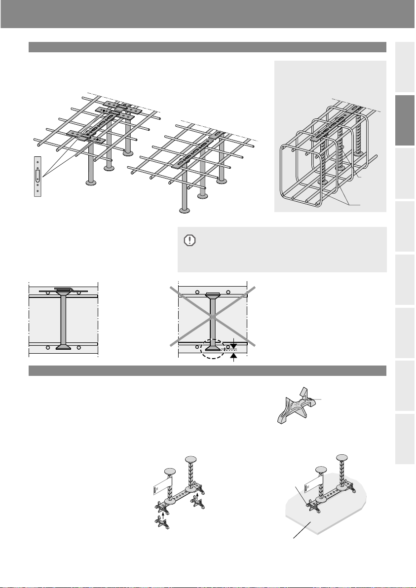
Mise en place inversée (par le dessous)
Fixation des éléments HDB ou HDB-S au ferraillage
Dalle
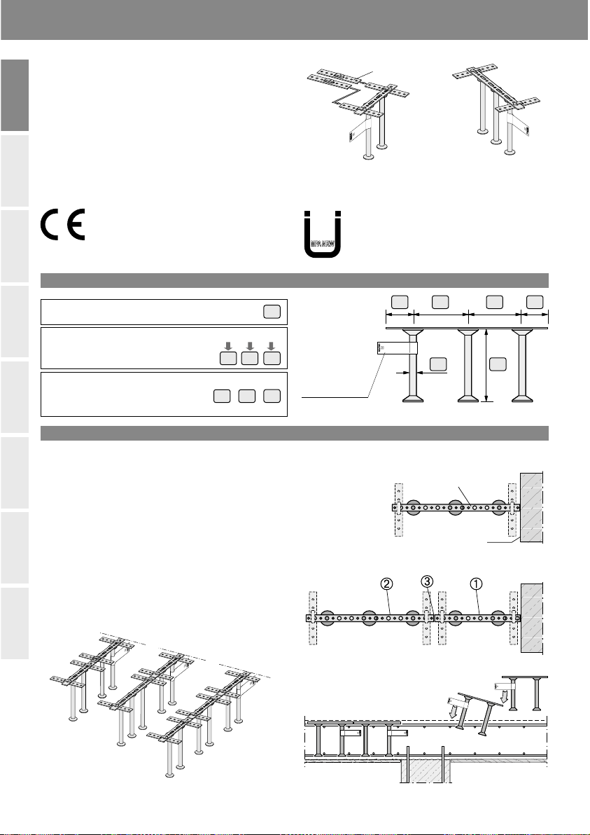
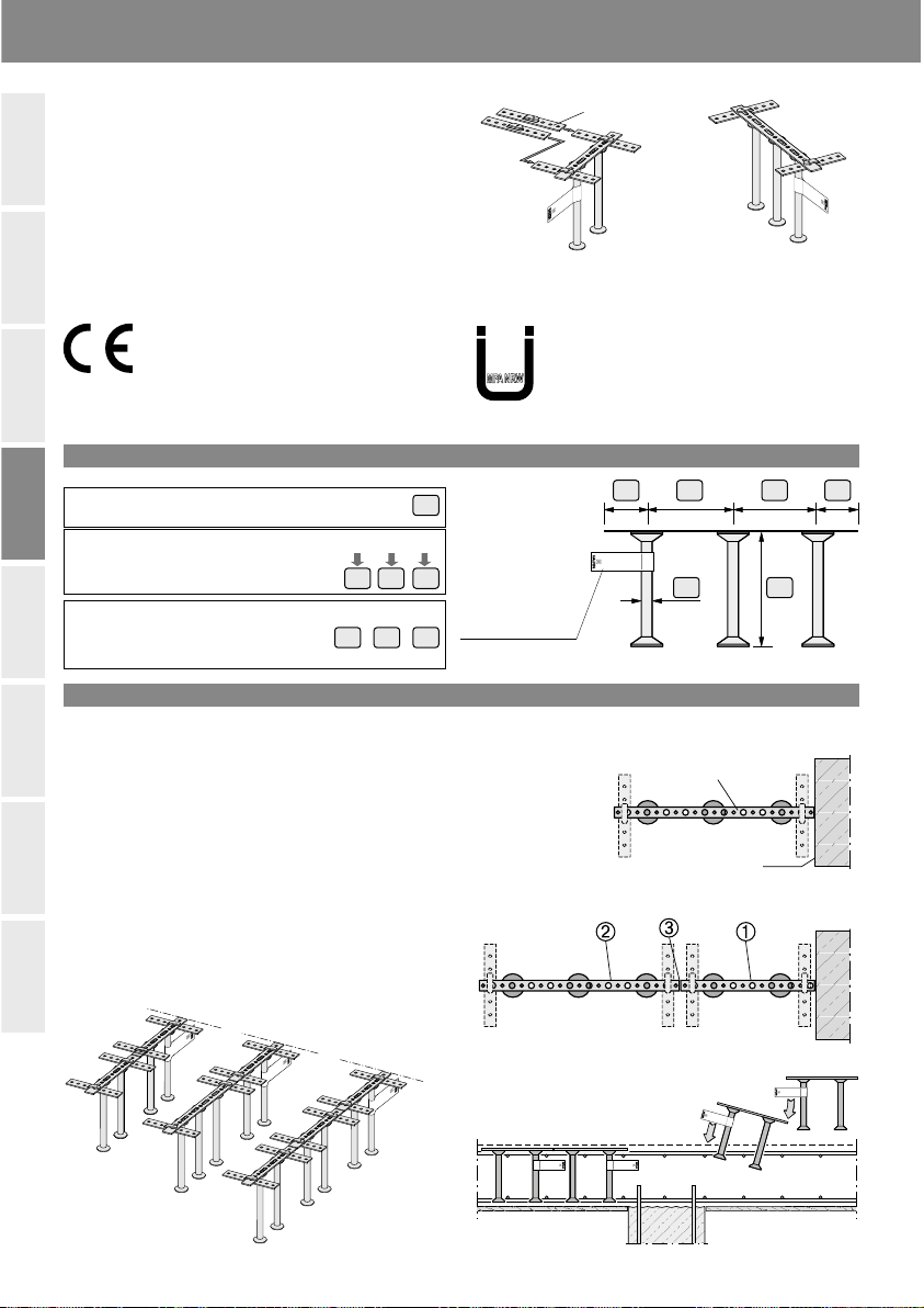
Fixation sur les aciers supérieurs:
sans plat de fixation
Plat de fixation
Element HDB, exemple avec 2 ancres
Mise en place sans plats de fixation:
Les éléments HDB-S sont posés au
dessus des cadres supérieurs
Fixation en parallèlement aux aciers supérieurs:
en utilisant les plats de fixation
Pour une utilisation dans des dalles
préfabriquées ou lorsque le ferraillage
supérieur est extrêmement dense, les
éléments HDB peuvent être position-
nés avant les armatures. Les cales
d’enrobage en pied d’élément assurent
une distance constante par rapport au
coffrage.
La capacité de charge totale de
l’armature HDB est ainsi garantie.
Si l’armature anti-poinçonnement doit
être insérée dans des pré-dalles, il faut
utiliser les armatures anti-poinçonne-
ment du modèle HDB-F, se référer au
catalogue technique HDB en vigueur.
Sur les coffrages en bois, les éléments
HDB peuvent être cloués avec les
cales d’enrobage, via le plat d’assem-
blage.
Marquage de la
dimension cnom
(enrobage en mm)
Cale d’enrobage type HDB ABST
Matière: KS = plastique,
disponible pour un enrobage du béton
cnom = 15, 20, 25, 30, 35, 40 mm
Coffrage en bois ou en acier
Cale
d‘enrobage
Fixation des
cales d‘enrobage
Sur les coffrages en acier, les élé-
ments HDB doivent être liaisonnés
aux armatures inférieures par des fils
d’acier.
Remarque:
• Les éléments HDB/HDB-S se mettent
toujours en place par le dessus du ferraillage.
• Les plats de fixation peuvent être attachés
à n’importe quel endroit du plat d’assemblage,
afin d’éviter tout chevauchement
Bonne position:
Mise en place avec
le plat de fixation
Mauvaise position:
Enrobage de béton cu
insuffisant
Il n‘est pas autorisé de combiner des pieds d’ancrage lisses
et des pieds d‘ancrage nervurés autour d’un même poteau.
Pour sécuriser l’installation, il est obligatoire de ligaturer
le plat d‘assemblage aux aciers supérieurs.

DeutschNederlands Español EnglishFrançaisČesky Svensk Polski
HALFEN HDB
Armaduras de punzonamiento
Instrucciones de montaje
Ø
A-306-07/09
A-306-07/09
A-306-07/09
A-306-07/09
HALFEN
Artern
Z-15.1-249
DIBt
Los elementos de punzonamiento HDB (-S) suministrados han
sido fabricados de acuerdo a las especificaciones del cliente y
en cumplimiento de las siguientes Certificados oficiales:
• HDB: Evaluación Técnica Europea ETA-12/0454;
• HDB-S: Certificado Alemán no. Z-15.1-249
Estas instrucciones se aplican para ambos tipos.
La pletina de sujeción (pedida por separado) se puede
conectar a cualquier punto en la pletina espaciadora para
un posicionamiento seguro en el refuerzode la estructura.
Elementos de HDB (figura 2a)
Los sistemas HDB se instalan acorde los planos de estructu-
ra y las especificaciones de los ingenieros. Después de colo-
car los refuerzos inferior y superior, los sistemas HDB se
insertan desde arriba a través del refuerzo (→ figura 3).
La distancia del primer perno al soporte (pilar) se especifica
en los planos de estructura.
Combinaciones de HDB (figura 2b)
Primero instale los HDB que están más cerca del apoyo.
Los siguientes Elementos están posicionados de manera
que los extremos de las pletinas de montaje se juntan
para formar una junta a tope.
Identificación
Notas para la instalación
HDB Armadura de punzonamiento,
certificado oficialmente, DIBt Berlin,
como refuerzo de punzonamiento en losas.
ETA-12/0454
HDB-S Sistema de elementos de punzonamiento,
certificado oficialmente, DIBt Berlin,
como refuerzo de cortante en losas y vigas.
N.º de certificado: Z-15.1-249
Número de pernos soldados, doble cabeza,
por sistema HDB:
Los sistemas están etiquetados
para identificarlos fácilmente,
ver ejemplo:
Nota: las siguientes dimensiones se
pueden personalizar bajo configuración
especial del HDB
Figura 1: vista lateral
La etiqueta de
identificación del
HDB va colocada
en el perno más
próximo al pilar
HDB-Elemento con 3 pernos
Figura 2a: Elemento HDB con 3 pernos - vista en planta
Figura 2b: Combinación de 2 elementos HDB: vista en planta
Figura 3: Inserte los elementos HDB desde
arriba a través del refuerzo superior
Figura 4: ejemplos de combinaciones
con 2 o 3 elementos HDB
Pletina de sujeción,
fácil de colocar
HDB (-S) elemento
con 3 pernos
HDB (-S) elemento
con 2 pernos
HDB -16 / 205 - 3
LA1 LA2
Lü
B
A
AC
LA1 LA2
LüLü
B C
CE DOP No.
H09-12/0454
HBD Pletina para montaje
Borde de pilar
8© 2020 · INST_HDB 04/19 · www.halfen.com

DeutschNederlands Español EnglishFrançaisČesky Svensk Polski
HALFEN HDB
Armaduras de punzonamiento
Instrucciones de montaje
Viga
cu
A-306-07/09
A-306-07/09
Estribos
Instalación invertida (desde abajo)
La fijación de los elementos HDB a la armadura
Losa
Instalación perpendicular
al refuerzo superior:
sin pletina de sujeción.
Nota:
• siempre coloque elementos HDB encima del
refuerzo superior
• para evitar la superposición de pletinas de
sujeción puede ser adjuntado en cualquier
lugar de la pletina de montaje
Elemento HDB,
ejemplo con 2 pernos
Instalación sin pletina de fijación:
Los elementos HDB-S se colocan en
la parte superior de los estribos.
Instalación paralela a la parte superior
refuerzo utilizando la pletina de fijación.
Correcto:
Instalación con
pletina de sujeción!
Incorrecto:
Insuficiente recubrimiento
del hormigón!
No esta permitido mezclar los pernos lisos y con los
pernos corrugados en un mismo soporte!
Para asegurar la correcta posición, se aconseja usar las
pletinas de montaje/sujeción en el refuerzo superior.
El sistema HDB también se puede
instalar en posición invertida en losas
prefabricadas o cuando el refuerzo
superior está extremadamente conges-
tionado. (La pletina de montaje estará
en la parte inferior del elemento).
La capacidad de transmisión de carga
de los HDB también está garantizada
para esta posición.
La armadura de punzonamiento
HALFEN tipo HDB-F se instala desde
arriba en losas prefabricadas.
Ver el catálogo técnico de „HALFEN
HDB“ para mayor información.
Con encofrado de madera, los elemen-
tos HDB se pueden clavar al encofrado
junto con los espaciadores.
Espaciador tipo HDB ABST
Material: KS = Plástico,disponible
para recubrimientos de hormigón
cnom = 15, 20, 25, 30, 35, 40 mm
HDB-S
Encofrado de acero o de madera
Espaciador
Con encofrado de acero, los elemen-
tos HDB deben estar atados a los
refuerzos inferiores con alambre.
Marca de medida
nominal del recubri-
miento cnom en el
espaciador
Instalar espaciador
9
© 2020 · INST_HDB 04/19 · www.halfen.com

DeutschNederlands Español EnglishFrançaisČesky Svensk Polski
A-306-07/09
A-306-07/09
A-306-07/09
HALFEN
Artern
Z-15.1-249
DIBt
Ø
A-306-07/09
10 © 2020 · INST_HDB 04/19 · www.halfen.com
HALFEN HDB Dwarskrachtwapening Montagehandleiding
De HALFEN HDB (-S) dwarskrachtwapening elementen
worden geleverd conform opgave opdrachtgever,
overeenkomstig Zulassungen
• voor HDB: Europees Technische Beoordeling
ETA-12/0454;
• voor HDB-S: Nr. Z-15.1-249
Deze montagehandleiding geldt voor beide typen.
De klemstrips (apart bestellen) zijn voor het positioneren
op en vastzetten aan de wapening en moeten aan de
montagestrip bevestigd worden.
HDB Elementen (Fig. 2a)
De montage van de HDB-elementen vindt plaats overeen-
komstig de gegevens van de wapeningstekening.
Nadat de onder- en bovenwapening gereed is, worden de
HDB elementen van bovenaf door de reeds aanwezige
bovenwapening gestoken (→ Fig. 3). Plaatsen van de eerste
elementen volgens wapeningsplan.
HDB - combinaties (Fig. 2b)
Als eerste worden de met de kolomrand gelijk liggende
elementen geplaatst.
De volgende elementen worden zo geplaatst,
dat de uiteinden van de montagestrip stomp op elkaar
aansluiten.
Controle
Montage
HDB-S, met Zulassung, DIBt Berlijn,
als dwarskrachtwapening.
Nr.: Z-15.1-249
Fig. 1: Zijaanzicht
Label zijde is
zijde oplegging.
(zie ook fig.3)
HDB 3-deuvel element
Fig. 2a: HDB Element met 3 deuvels – Bovenaanzicht
Fig. 2b: HDB Element combinatie uit 2 of 3 elementen –
Bovenaanzicht
HDB montagestrip
Kolomrand
Fig. 3: De ponswapeningselementen worden
van boven door de reeds aanwezige
bovenwapening gestoken
Fig. 4: Voorbeelden van HDB
combinaties uit 2 of 3 elementen:
klemstrip, opschuifbaar
HDB 3-deuvel
element
HDB 2-deuvel
element
Het aantal aangelaste dubbelkop-deuvels per HDB
element controleren.
De afmeting controleren, zoals
aangegeven op de pakbon, bijv.:
Alleen bij HDB speciale uitvoeringen
worden maten aangegeven:
HDB -16 / 205 - 3
LA1 LA2
Lü
B
A
AC
HDB met Europees Technische Goedkeuring,
DIBt Berlijn, als ponswapening in beton-
elementen. ETA-12/0454
LA1 LA2
LüLü
B C
CE DOP No.
H09-12/0454

DeutschNederlands Español EnglishFrançaisČesky Svensk Polski
Balksituatie
cu
A-306-07/09
A-306-07/09
11
© 2020 · INST_HDB 04/19 · www.halfen.com
HALFEN HDB Dwarskrachtwapening Montagehandleiding
Het vooraf aanbrengen van de HDB elementen, bevestigd op afstandhouders
Het achteraf aanbrengen van de HDB elementen, ophangen aan de bovenwapening middels klemstrips
Vloersituatie
Haaks op de bovenwape-
ning: inbouw zonder
klemstrippen
HDB element, bijv. met 2 deuvel
Inbouw zonder klemstrip:
De HDB-S elementen worden met de
montagestrip op de beugel bevestigd
HDB-S
beugel
Parallel aan de
bovenwapening:
inbouw met klem-
strippen
Wanneer er sprake is van een breed-
plaatvloer/schil kan het wenselijk zijn
om de HDB elementen in de breed-
plaatschil mee te storten om zo geen
nuttige hoogte te verliezen.
De HDB elementen zullen dan op de
meegeleverde afstandhouders beves-
tigd kunnen worden. Ook wanneer er
sprake is van fijnmazige bovenwape-
ning kan er voor gekozen worden om
de HDB elementen vooraf te monte-
ren om conflicten met de bovenwape-
ning te vermijden.
Informatie over accessoires zoals
klemstrips en afstandhouders is te
vinden in onze brochure ‘HALFEN
HDB technische productinformatie’.
Codering dekking
cnom op afstand-
houder
Afstandhouder HDB ABST
Uitvoering: KS = kunststof,
leverbaar voor betondekkingen:
cnom 15, 20, 25, 30, 35, 40 mm
stalen of houten bekisting
Afstandhouder
Bevestiging op
afstandhouder
Montagetips:
• HDB-S elementen altijd op de
bovenwapening leggen
• Om overlappingen van de klemstrippen
te voorkomen, kunnen ze op elke willekeurige
plaats op de montagestrip bevestigd worden.
Goed:
Inbouw met
klemstrippen
Fout:
Onder betondekking
blijven
Een combinatie van gladde en geribde ankers binnen één
oplegging is niet toegestaan!
Indien gewenst, kan de montagestrip met binddraad aan
de bovenwapening worden bevestigd.

DeutschNederlands Español EnglishFrançaisČesky Svensk Polski
A-306-07/09
A-306-07/09
Ø
A-306-07/09
A-306-07/09
12 © 2020 · INST_HDB 04/19 · www.halfen.com
HALFEN HDB Zbrojenie na przebicie Instrukcja montażu
Dostarczone elementy HDB zostały wyprodukowane we-
dług danych zleceniodawcy, zgodnie z oceną techniczną
ETA-12/0454.
Listwy montażowe (zamawiane osobno) służą do
stabilizacji elementu HDB na zbrojeniu i nasuwane są
w dowolnym miejscu listwy perforowanej.
Elementy HDB (rys. 2a)
Montaż elementów HDB wykonać zgodnie z rysunkami
zbrojenia projektu wykonawczego. Po ułożeniu dolnego i
górnego zbrojenia, elementy HDB wsuwane są od góry
(→ rys. 3). Odległość pierwszego trzpienia od podpory
przyjąć z rysunku zbrojenia.
Zestaw elementów HDB (rys.2b)
Jako pierwsze montowane są elementy przylegające do
podpory. Kolejne elementy układać w taki sposób, aby
końce listew perforowanych przylegały do siebie.
Oznaczenie
Montaż
Etykieta HDB
oznacza trzpień
od strony
podpory
Element HDB z 3 trzpieniami
Rys. 2a: Element HDB z 3 trzpieniami
Rys. 2b: Zestaw 2 elementów HDB
HDB Perforowana
listwa stalowa
Krawędź słupa
Rys. 3: Montaż elementów HDB na
górnym zbrojeniu
Rys. 4, Przykłady zestawów złożonych z elementów
2 lub 3 trzpieniowych
Listwa montażowa
Element HDB
z 3 trzpieniami
Element HDB
z 2 trzpieniami
Ilość trzpieni w elemencie:
Sprawdzić wymiary podane w
dokumencie WZ, np.:
Uwaga: wymiary Lü, LA1, LA2 poda-
wane są tylko w przypadku
niestandardowych elementów HDB
HDB -16 / 205 - 3
LA1 LA2
Lü
B
A
AC
Trzpienie stalowe HDB jako
zbrojenie na przebicie w płytach,
DIBt Berlin, ETA-12/0454
LA1 LA2
LüLü
B C
CE DOP No.
H09-12/0454

DeutschNederlands Español EnglishFrançaisČesky Svensk Polski
Belka
A-306-07/09
A-306-07/09
cu
HDB-S
Strzemię
13
© 2020 · INST_HDB 04/19 · www.halfen.com
HALFEN HDB Zbrojenie na przebicie Instrukcja montażu
Montaż od dołu
Przymocowanie elementów HDB do zbrojenia
Płyta stropowa
Prostopadle do prętów gór-
nego zbrojenia: zamocowa-
nie bez listew montażowych
Element HDB, np. element 2 trzpieniowy
Montaż bez listew montażowych:
Listwy perforowane elementów
HDB-S opiera się na strzemionach.
Równolegle do
prętów górnego
zbrojenia:
zamocowanie przy
pomocy listew
montażowych
W stropach prefabrykowanych lub
przy bardzo dużych średnicach prętów
górnego zbrojenia, elementy HDB
mogą być stosowane jako odwrócone
tj. z listwami perforowanymi na dole.
Dla takiego montażu, zapewniona
jest również pełna nośność HDB.
Przy montażu od góry, w stropach
prefabrykowanych, stosowane są 2
częściowe listwy HDB-F. Sposób
wbudowania zamieszczony jest w
Katalogu technicznym HALFEN HDB.
Do szalunków drewnianych HDB
mogą być przybijane razem z
elementami dystansowymi. Przy
zastosowaniu szalunków stalowych
listwy perforowane powinny być
przywiązane do dolnego zbrojenia.
Oznaczenie wymiaru
cnom na elemencie
dystansowym
Element dystansowy HDB ABST
Materiał: KS = tworzywo sztuczne,
dostarczane dla otulin betonowych
cnom 15, 20, 25, 30, 35, 40 mm
Szalunek stalowy lub drewniany
Elementy
dystansowe
Nasunąć elementy
dystansowe
Uwaga:
• elementy HDB opierać zawsze na górnym
zbrojeniu
• w celu uniknięcia zachodzenia na siebie
listew montażowych, mogą one być
montowane w dowolnym miejscu listwy
perforowanej.
Prawidłowo:
Montaż z listwami
montażowymi
Źle:
Nie zachowana otulina
betonowa!
Zastosowanie trzpieni gładkich i żebrowanych przy jednym
słupie jest niedopuszczalne!
Uwaga! Dla stabilizacji położenia należy przywiązać element
HDB drutem do zbrojenia.

DeutschNederlands Español EnglishFrançaisČesky Svensk Polski
A-306-07/09
HALFEN
Artern
Z-15.1-249
DIBt
Ø
A-306-07/09
A-306-07/09
A-306-07/09
14 © 2020 · INST_HDB 04/19 · www.halfen.com
HALFEN HDB Skjuvankare Monteringsanvisning
HDB(-S) skjuvankarna är tillverkade enligt
leverantörens specifikationer och enligt
typgodkännande nr. ETA-12/0454 och nr.
Z-15.1-249 (för HDB-S).
Dessa instruktioner gäller för båda typerna.
Klämblecken (beställs separat) kan monteras var som
helst på distansskenan för att förankra skjuvankarna till
armeringen.
HDB-moduler (Bild 2a)
Placeringen av HDB-modulerna ska följa armeringsritningen.
Efter att det övre och undre armeringsnätet är på plats
monteras HDB- modulen ovanifrån genom armeringen
(→ bild 3). Avståndet från det 1. ankaret till upplaget står
angivet på armeringsritningen. Justera modulens position,
så att änden på distansplåten är i linje med upplagets kant.
HDB kombinationer (Bild 2b)
Börja med att montera HDB-moduler som ansluter till
pelarens kant. Montera därefter de övriga modulerna
så att distansskenorna ligger i linje med varandra och
så nära som möjligt.
Märkning
Monteringsanvisning
HDB-S för skjuvarmering är tillverkade enligt
typgodkännande nr. Z-15.1-249 DIBt, Berlin,
Tyskland.
Bild 1: Sidovy
HDB-etiketten
markerar ankaret
närmast pelaren.
HDB - 3 skjuvankare
Bild 2a: HDB 3 skjuvankare
Bild 2b: Två efter varandra liggande HDB-moduler
HDB distansskena
Pelarkant
Bild 3: Montering av HDB-moduler genom
det övre armeringsskiktet
Bild 4: Exempel på kombination av HDB- moduler
med 2 eller 3 ankare
Klämbleck, clip-on
HDB(-S) -modul
med 3 skjuvankare
HDB(-S) -modul
med 2 skjuvankare
Antal påsvetsade dubbelhuvade ankare
per HDB-element:
Kontrollera att dimensionerna på
etiketten överensstämmer med
fraktsedeln t.ex.:
Noter: Följande dimensioner anges
endast för HDB - specialutföranden:
HDB -16 / 205 - 3
LA1 LA2
Lü
B
A
AC
NORDCERT
Certificate
LA1 LA2
LüLü
B C
HDB Skjuvankare mot genomstansning
är tillverkade enligt typgodkännande
nr. ETA-12/0454 DIBt, Berlin, Tyskland.
CE DOP No.
H09-12/0454

DeutschNederlands Español EnglishFrançaisČesky Svensk Polski
Balk
cu
A-306-07/09
A-306-07/09
15
© 2020 · INST_HDB 04/19 · www.halfen.com
HALFEN HDB Skjuvankare Monteringsanvisning
Omvänd montering (underifrån)
Fixering av HDB-moduler i armeringen
Betongplatta
Vinkelrätt mot det övre
armeringsskiktet: utan
klämbleck
HDB- modul, t.ex. tvåpunktsstöd
Fixering utan klämbleck:
HDB-S- moduler läggs ovanpå bygeln.
HDB-S
Bygel
Parallellt mot det övre armerings-
skiktet: med klämbleck
När HDB-ankare används i t.ex. platt-
bärlag eller när överkantsarmeringen
ligger väldigt tätt, kan modulerna
monteras underifrån (monterings-
skenan nederst). Oavsett montage,
under- eller ovaninfrån, erhålls full ka-
pacitet från HDB skjuvankarna.
Använd HDB-F-ankare om skjuvame-
ringen ska monteras från ovansidan i
plattbärlag, se broschyren ”HALFEN
Durchstanz- und Querkraftbewehrung
HDB ”, tekniska information på tyska.
HDB-ankare kan fästas till träform
genom att plastdistanser spikas fast.
Används stålform kan distansskenan
najas fast till det undre armeringsnä-
tet.
Dimensionsmått
cnom på distansen
Plastdistanser typ HDB ABST
finns i betongtäckskiktet
cnom 15, 20, 25, 30, 35, 40 mm
Stål-eller träform
Plastdistans
Fixera plastdistanser
Observera:
• HDB-moduler alltid ovanpå armeringsjärnen.
• Klämblecket kan fästas var som helst på
distansskenan.
På så sätt kan överlappning undvikas.
Rätt:
Fixering med
klämbleck
Fel:
Täckande betong-
skickt otillräckligt!
Man får absolut inte använda både släta och räfflade ankare
på samma pelare!
Observera: För att fixera modulen under gjutningen rekommen-
derar vi att distansskenan najas fast till armeringen.

Česky DeutschNederlands Español EnglishFrançaisSvensk Polski
A-306-07/09
HALFEN
Artern
Z-15.1-249
DIBt
Ø
A-306-07/09
A-306-07/09
A-306-07/09
16 © 2020 · INST_HDB 04/19 · www.halfen.com
HALFEN HDB Smykové lišty Montážní návod
Dodané smykové lišty HALFEN HDB (-S) byly vyrobeny po-
dle údajů objednatele s dodržením těchto certifikátů:
• HDB: Evropský technický certifikát ETA-12/0454;
• HDB-S: Všeobecné povolení stavebním dozorem
č. Z-15.1-249 a Z-15.1-270.
Tento montážní návod platí pro oba typy.
Svěrací třmínky (separátní objednávka) pro zajištění polohy
na výztuži stavebního dílce se podle potřeby nasunou na
montážní lištu na libovolném místě.
Prvky HDB (obr. 2a)
Montáž prvků HDB se provádí podle údajů plánu výztuže.
Po položení spodní a horní výztuže se prvky HDB nasadí
shora mezi výztuž (→ obr. 3).
Vzdálenost 1. kotvy a podpěry uvádí plán výztuže.
Kombinace HDB (obr. 2b)
Nejprve se zabudují prvky HDB na podpěru. Další prvky
se uloží tak, aby se konce montážních lišt dotýkaly.
Označení
Montážní pokyny
HDB-S Smykové lišty povoleny stavebním dozo-
rem, certifikát vystavil DIBt (Německý ústav sta-
vební techniky) Berlín, jako výztuž smykových sil.
Číslo certifikátu Z-15.1-249.
Počet navařených kotev s dvojitými hlavami
na jeden prvek HDB:
Zkontrolujte rozměry,
viz dodací list, např.:
Pozor: tyto rozměry se uvádějí
pouze u atypických HDB:
Obr. 1: Boční pohled
Etiketa HDB
označuje
1. kotvu od
sloupu
HDB-prvek se 3 kotvami
Obr. 2a: HDB se 3 kotvami
Obr. 2b: Kombinace 2 prvků HDB
HDB montážní pásek
vnější hrana sloupu
Obr. 3: Osazení prvků HDB
Obr. 4:
Příklady kombinací 2 nebo 3 prvků HDB
LA1 LA2
LüLü
B C
svěrací třmínek,
pro nasunutí
HDB (-S)
se 3 kotvami
HDB (-S)
se 2 kotvami
HDB -16 / 205 - 3
LA1 LA2
Lü
B
A
AC
HDB Smykové lišty povoleny stavebním dozo-
rem, certifikát vystavil DIBt (Německý ústav
stavební techniky) Berlín, jako výztuž proti
protlačení pro desky.
Číslo certifikátu ETA-12/0454.
CE DOP No.
H09-12/0454

Česky DeutschNederlands Español EnglishFrançaisSvensk Polski
Průvlak
cu
A-306-07/09
A-306-07/09
17
© 2020 · INST_HDB 04/19 · www.halfen.com
HALFEN HDB Smykové lišty Montážní návod
Montáž v opačném pořadí (zdola)
Upevnění prvků HDB na výztuž
Stropní desky
Napříč horní výztuží: montáž
bez svěracích třmínků
Prvek HDB, např. prvek se 2 kotvami
Montáž bez svěracích třmínků:
prvky HDB-S se položí montážním
páskem na třmínky
třmínek
Paralelně s horní výztuží:
montáž pomocí svěracích
třmínků
Pro použití ve filigránových stropech
nebo v případě husté horní podélné
výztuže lze prvky HDB také ukládat
hlavou dolů (montážní pásky leží
dole). I v této montážní poloze je
zaručena plná nosnost smykových lišt
HDB.
Pro montáž shora u filigránových
stropů se používají HDB-F.
Další informace jsou uvedeny v
katalogu HALFEN HDB.
U dřevěného bednění je možno prvky
HDB přibít společně s distančníky na
bednění.
Při použití ocelového bednění by
měly být montážní lišty spojeny rádlo-
vacím drátem se spodní výztuží.
Značení rozměru cnom
na distančníku
Plastový distančník typu HDB ABST
dodáváme pro betonová krytí
cnom = 15, 20, 25, 30, 35, 40 mm
Ocelové nebo dřevěné
bednění
Distančník
Nasazení
distančníku
Pozor:
• Prvky HDB vždy pokládejte na horní výztuž
• Svěrací třmínky můžete montovat na libovol-
ném místě montážního pásku – předejdete
tak jejich překrývání.
Správně:
Montáž se svěracími
třmínky
Špatně:
Nedostatečné krytí betonem!
Současné použití hladkých a žebrovaných kotev na jednom
sloupu není přípustné!
Pro zajištění polohy můžete montážní pásky připevnit rádlo-
vacím drátem na horní výztuž.
HDB-S

18 © 2020 · INST_HDB 04/19 · www.halfen.com

For more information on the products featured here, please contact Leviat:
Notes regarding this catalogue
© Protected by copyright. The construction applications and details provided in this publication are
indicative only. In every case, project working details should be entrusted to appropriately qualified
and experienced persons. Whilst every care has been exercised in the preparation of this publication
to ensure that any advice, recommendations or information is accurate, no liability or responsibility
of any kind is accepted by Leviat for inaccuracies or printing errors. Technical and design changes
are reserved. With a policy of continuous product development, Leviat reserves the right to modify
product design and specification at any time.
Leviat.com
For information on certified management systems and standards, see www.halfen.com
Australia
Leviat
98 Kurrajong Avenue,
Mount Druitt Sydney, NSW 2770
Tel: +61 - 2 8808 3100
Email: info.au@leviat.com
Austria
Leviat
Leonard-Bernstein-Str. 10
Saturn Tower, 1220 Wien
Tel: +43 - 1 - 259 6770
Email: info.at@leviat.com
Belgium
Leviat
Borkelstraat 131
2900 Schoten
Tel: +32 - 3 - 658 07 20
Email: info.be@leviat.com
China
Leviat
Room 601 Tower D,
Vantone Centre
No. A6 Chao Yang Men Wai Street
Chaoyang District
Beijing · P.R. China 100020
Tel: +86 - 10 5907 3200
Email: info.cn@leviat.com
Czech Republic
Leviat
Business Center Šafránkova
Šafránkova 1238/1
155 00 Praha 5
Tel: +420 - 311 - 690 060
Email: info.cz@leviat.com
Finland
Leviat
Vädursgatan 5
412 50 Göteborg / Sweden
Tel: +358 (0)10 6338781
Email: info.fi@leviat.com
France
Leviat
18, rue Goubet
75019 Paris
Tel: +33 - 1 - 44 52 31 00
Email: info[email protected]
Germany
Leviat
Liebigstrasse 14
40764 Langenfeld
Tel: +49 - 2173 - 970 - 0
Email: info.de@leviat.com
India
Leviat
309, 3rd Floor, Orion Business Park
Ghodbunder Road, Kapurbawdi,
Thane West, Thane,
Maharashtra 400607
Tel: +91 - 22 2589 2032
Email: info.in@leviat.com
Italy
Leviat
Via F.lli Bronzetti 28
24124 Bergamo
Tel: +39 - 035 - 0760711
Email: info.it@leviat.com
Malaysia
Leviat
28 Jalan Anggerik Mokara 31/59
Kota Kemuning,
40460 Shah Alam Selangor
Tel: +603 - 5122 4182
Email: info.my@leviat.com
Netherlands
Leviat
Oostermaat 3
7623 CS Borne
Tel: +31 - 74 - 267 14 49
Email: info.nl@leviat.com
New Zealand
Leviat
2/19 Nuttall Drive, Hillsborough,
Christchurch 8022
Tel: +64 - 3 376 5205
Email: info.nz@leviat.com
Norway
Leviat
Vestre Svanholmen 5
4313 Sandnes
Tel: +47 - 51 82 34 00
Email: info.no@leviat.com
Philippines
Leviat
2933 Regus, Joy Nostalg,
ADB Avenue, Ortigas Center
Pasig City
Tel: +63 - 2 7957 6381
Email: info.ph@leviat.com
Poland
Leviat
Ul. Obornicka 287
60-691 Poznań
Tel: +48 - 61 - 622 14 14
Email: info.pl@leviat.com
Singapore
Leviat
14 Benoi Crescent
Singapore 629977
Tel: +65 - 6266 6802
Email: info.sg@leviat.com
Spain
Leviat
Polígono Industrial Santa Ana
c/ Ignacio Zuloaga, 20
28522 Rivas-Vaciamadrid
Tel: +34 - 91 632 18 40
Email: info.es@leviat.com
Sweden
Leviat
Vädursgatan 5
412 50 Göteborg
Tel: +46 - 31 - 98 58 00
Email: info.se@leviat.com
Switzerland
Leviat
Hertistrasse 25
8304 Wallisellen
Tel: +41 - 44 - 849 78 78
Email: info.ch@leviat.com
United Kingdom
Leviat
A1/A2 Portland Close
Houghton Regis LU5 5AW
Tel: +44 - 1582 - 470 300
Email: info.uk@leviat.com
United States of America
Leviat
6467 S Falkenburg Rd.
Riverview, FL 33578
Tel: (800) 423-9140
Email: info.us@leviat.us
For countries not listed
Email: info@leviat.com
Halfen.com

Imagine. Model. Make. Leviat.com
© 2020 U-310 – 09/20 PDF 11/20
This manual suits for next models
1
Table of contents
Languages: