Leviton 47611-GT4 User manual

47611 – GT4
Internet Gateway
Broadband Internet Access
4-Port Switch
User's Manual


i
Table of Contents
CHAPTER 1 INTRODUCTION .............................................................................................1
Internet GatewayFeatures................................................................................................1
Package Contents ..............................................................................................................3
Physical Details..................................................................................................................4
CHAPTER 2 INSTALLATION...............................................................................................6
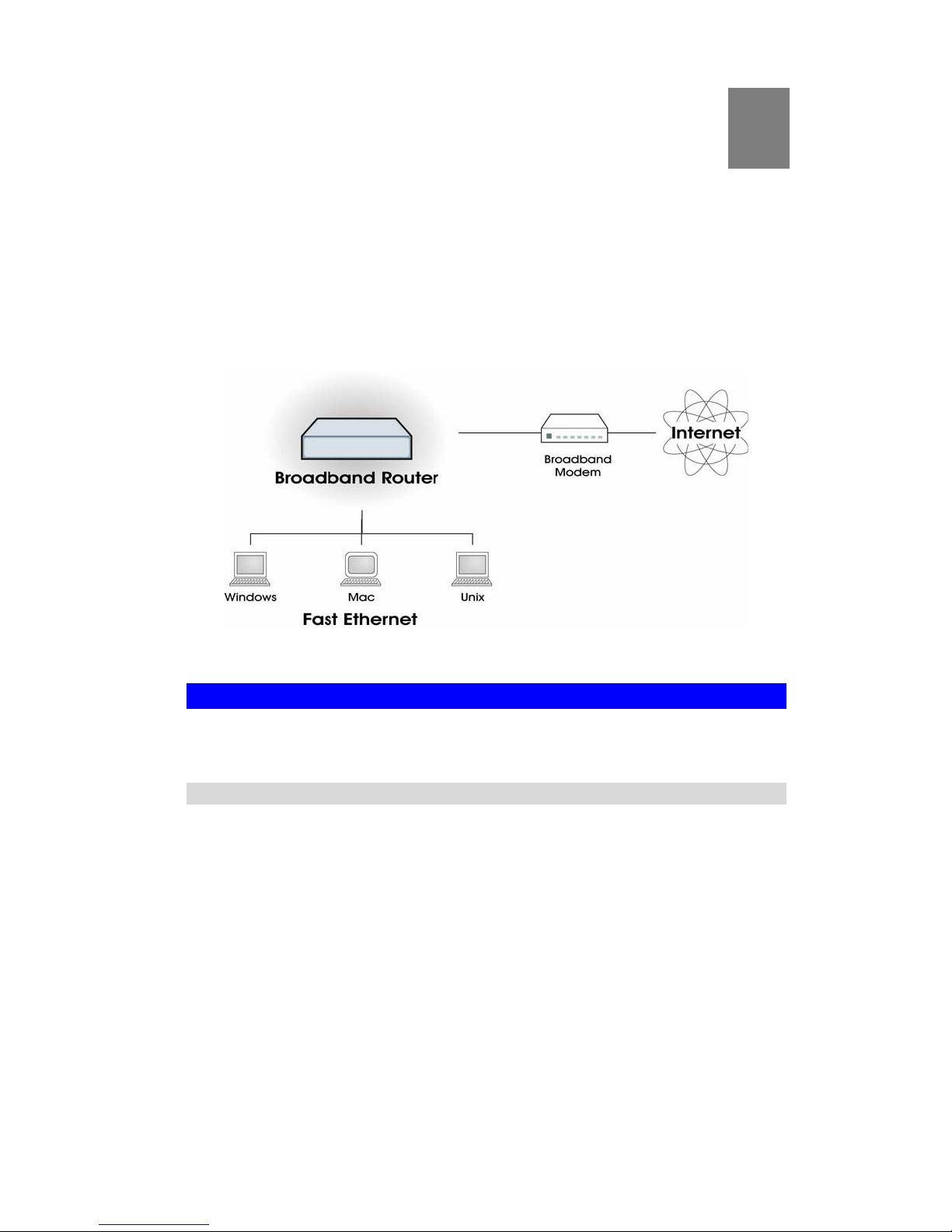
Requirements.....................................................................................................................6
Procedure...........................................................................................................................6
CHAPTER 3 SETUP ................................................................................................................9
Overview ............................................................................................................................9
Configuration Program ..................................................................................................10
Setup Wizard...................................................................................................................12
LAN Screen......................................................................................................................15
Password Screen..............................................................................................................17
CHAPTER 4 PC CONFIGURATION..................................................................................18
Overview ..........................................................................................................................18
Windows Clients..............................................................................................................18
Macintosh Clients............................................................................................................30
Linux Clients....................................................................................................................30
Other Unix Systems.........................................................................................................30
CHAPTER 5 OPERATION AND STATUS.........................................................................31
Operation.........................................................................................................................31
Status Screen....................................................................................................................31
Connection Status - PPPoE ............................................................................................33
Connection Status - PPTP ..............................................................................................36
Connection Status - Telstra Big Pond............................................................................37
Connection Details - SingTel RAS.................................................................................38
Connection Details - Fixed/Dynamic IP Address .........................................................39
CHAPTER 6 ADVANCED FEATURES..............................................................................41
Overview ..........................................................................................................................41
Blocked Packet..................................................................... Error! Bookmark not defined.
Dynamic DNS...................................................................................................................48
Advanced Internet Screen ..............................................................................................50
Virtual Servers.................................................................................................................54
WAN Port Configuration ...............................................................................................58
CHAPTER 7 ADVANCED ADMINISTRATION...............................................................61
Overview ..........................................................................................................................61
Config File........................................................................................................................62
Logs...................................................................................................................................63
Network Diag...................................................................................................................65
Options.............................................................................................................................66
PC Database.....................................................................................................................68
Remote Admin.................................................................................................................72
Routing.............................................................................................................................73
Security.............................................................................................................................77
Upgrade Firmware..........................................................................................................79

ii
APPENDIX A TROUBLESHOOTING................................................................................80
Overview ..........................................................................................................................80
General Problems............................................................................................................80
Internet Access.................................................................................................................80
APPENDIX B SPECIFICATIONS........................................................................................82
Multi-Function Internet Gateway..................................................................................82
Regulatory Approvals.....................................................................................................83
Copyright ©2004. All Rights Reserved.
Document Version: 1.3 (August, 2004)
All trademarks and trade names are the properties of their respective owners.

1
Chapter 1
Introduction
This Chapter provides an overview of the Internet Gateway’s features and
capabilities.
Congratulations on the purchase of your new Internet Gateway. The Internet Gateway is a
multi-function device providing the following services:
•Shared Broadband Internet Access for all LAN users.
•4-Port Switch for 10BaseT or 100BaseT connections.
Figure 1: Internet Gateway
Internet Gateway Features
The Internet Gateway incorporates many advanced features, which have been carefully de-
signed to provide sophisticated functions, while being easy to use.
Internet Access Features
•Shared Internet Access. All users on the LAN or WLAN can access the Internet
through the Internet Gateway using only a single external IP Address. The local (invalid)
IP Addresses are hidden from external sources. This process is called NAT (Network Ad-
dress Translation).
•DSL & Cable Modem Support. The Internet Gateway has a 10/100BaseT Ethernet
port for connecting a DSL or Cable Modem. All popular DSL and Cable Modems are sup-
ported. SingTel RAS and Big Pond (Australia) login support also is included.
•PPPoE, PPTP, SingTel RAS and Telstra Big Pond Support.The Internet (WAN
port) connection supports PPPoE (Peer-to-Peer Protocol over Ethernet), PPTP (Peer-to-
Peer Tunneling Protocol), SingTel RAS and Telstra Big Pond (Australia), as well as "Di-
rect Connection" type services.
•Fixed or Dynamic IP Address. On the Internet (WAN port) connection, the Internet
Gateway supports both Dynamic IP Address (IP Address is allocated on connection) and
Fixed IP Address.
1

Internet Gateway User Guide
2
Advanced Internet Functions
•Communication Applications. Support for Internet communication applications, such
as interactive Games, Telephony, and Conferencing, which are often difficult to use when
behind a Firewall, is included.
•Special Internet Applications. Applications which use non-standard connections or
port numbers are normally blocked by the Firewall. The ability to define and allow such
applications is provided to enable such applications to be used normally.
•Virtual Servers. This feature allows Internet users to access Internet servers on your
LAN. The required setup is quick and easy.
•DMZ. One (1) PC on your local LAN can be configured to allow unrestricted 2-way
communication with Servers or individual users on the Internet. This provides the ability
to run programs which are incompatible with Firewalls.
•URL Filter. Use the URL Filter to block access to undesirable Web sites by LAN users.
•Internet Access Log. See which Internet connections have been made.
•Blocked Packet. Using the Blocked Packet feature, you can assign LAN users to differ-
ent groups, and determine which Internet services are available to each group.
•VPN Pass through Support. PCs with VPN (Virtual Private Networking) software
using PPTP, L2TP and IPSec) are transparently supported; no configuration is required.
LAN Features
•4-Port Switch. The Internet Gateway incorporates a 4-port 10/100BaseT Switch, mak-
ing it easy to create or extend your LAN.
•DHCP Server Support. DHC (Dynamic Host Configuration Protocol) provides a
dynamic IP address to PCs and other devices upon request. The Internet Gateway can act
as a DHCP Server for devices on your local LAN and WLAN.
•Multi Segment LAN Support. LANs containing one or more segments are supported
via the Internet Gateway’s RIP (Routing Information Protocol) support and built-in static
routing table.
Configuration & Management
•Easy Setup. Use your WEB browser from anywhere on the LAN for configuration.
•Configuration File Upload/Download. Save (download) the configuration data from
the Internet Gateway to your PC, and restore (upload) a previously-saved configuration
file to the Internet Gateway.
•Remote Management. The Internet Gateway can be managed from any PC on your
LAN. And, if the Internet connection exists, it also can (optionally) be configured via the
Internet.
•UPnP Support. UPnP (Universal Plug and Play) allows automatic discovery and
configuration of the Internet Gateway. UPnP is supported by Windows ME, XP, or later.
Security Features
•Password - Protected Configuration. Optional password protection is provided to
prevent unauthorized users from modifying the configuration data and settings.
•NAT Protection. An intrinsic side effect of NAT (Network Address Translation) tech-
nology is that by allowing all LAN users to share a single IP address, the location and the
existence of each PC are hidden. From the external viewpoint, there is no network, only a
single device - - the Internet Gateway.

Introduction
3
•Stateful Packet Inspection Firewall. All incoming data packets are monitored and all
incoming server requests are filtered, thus protecting your network from malicious attacks
from external sources.
•Protection Against DoS attacks. DoS (Denial of Service) attacks can flood your
Internet connection with invalid packets and connection requests, using so much band-
width and so many resources that Internet access becomes unavailable. The Internet
Gateway incorporates protection against DoS attacks.
Package Contents
The following items should be included:
•The Internet Gateway Unit
•Power Adapter
•Quick Installation Guide
If any of the above items are damaged or missing, please contact your dealer immediately.

Internet Gateway User Guide
4
Physical Details
Front-mounted LEDs
Figure 2: Front Panel
Power On - Power on.
Off - No power.
Status (Red) On - Error condition.
Off - Normal operation.
Blinking - This LED blinks during start up.
LAN For each port, there are 2 LEDs
•Link/Act (Activity)
•On - on the corresponding LAN (hub) port.
•Flashing - Data is being Corresponding LAN (hub) port is active.
•Off - No active connection transmitted or received via the corre-
sponding LAN (hub) port.
•100
•On - Corresponding LAN (hub) port is using 100BaseT.
•Off - Corresponding LAN (hub) port connection is using
10BaseT, or no active connection.
WAN On - Connection to the broadband modem attached to the WAN (Internet)
port is established.
Off - No connection to the broadband modem on the WAN (Internet) port.
Flashing - Data is being transmitted or received via the WAN port.

Introduction
5
Rear Panel
Figure 3: Rear Panel
Reset Button This button has two (2) functions:
•Reboot. When pressed and released, the Internet Gateway will
reboot (restart).
•Clear All Data. This button also can be used to clear ALL data
and restore ALL settings to the factory default values. Hold in
for 5-7 seconds.
To Clear All Data and restore the factory default values:
1. Power Off.
2. Hold the Reset Button down while you Power On.
3. Keep holding the Reset Button for a few seconds, until the RED
LED has flashed TWICE.
4. Release the Reset Button. The Internet Gateway is now using the
factory default values.
WAN port
(10/100BaseT) Connect the DSL or Cable Modem here. If your modem came with a
cable, use the supplied cable. Otherwise, use a standard LAN cable.
10/100BaseT
LAN connections Use standard LAN cables (RJ45 connectors) to connect your PCs to
these ports.
Note:
Any LAN port on the Internet Gateway will automatically function
as an "Uplink" port when required. Just connect any port to a normal
port on the other hub, using a standard LAN cable.
Power port Connect the supplied power adapter here.

6
Chapter 2
Installation
This Chapter covers the physical installation of the Internet Gateway.
Requirements
•Network cables. Use standard Cat5 or Cat5e cables with RJ45 connectors.
•TCP/IP protocol must be installed on all PCs.
•For Internet Access, an Internet Access account with an ISP, and either of a DSL or Cable
modem (for WAN port usage)
Procedure
Figure 4: Installation Diagram
Installation:
Align the mounting pins with the grid holes on the back of the enclosure. With the mount-
ing pin plungers in the “out” position, press the unit into the grid in the desired location,
then secure by pushing the plungers in.
Cabling the Internet Gateway
The Internet Gateway has four network ports. The ports numbered 1-4 can be used to con-
nect a variety of equipment, including computers, printers, scanners or other network
peripherals. Additionally, the Internet Gateway features a WAN port. The Internet Gate-
way ncan replace an existing hub or switch that has no more than four devices connected,
or that hub/switch can be cascaded with the Internet Gateway (see the instruction sheet for
your hub or switch). Any of the ports numbered 1-4 can be used as an Uplink port.
2

Introduction
7
NOTE: Ensure that the modem and computers are shut down and powered OFF.
1. Using Cat5/5e Patch Cords connect the WAN port of the Internet Gateway to the
Ethernet port of your modem. If the modem is in the Structured Media™ Center (SMC),
connect it directly. If your modem is in a remote location, connect it to the jack on the
Cat5e Voice and Data Module that corresponds to the wallplate the modem is connected
to.
2. Using Cat 5/53 Patch Cords, connect the LAN ports of the Internet Gateway to the jacks
on the Cat5e Voice and Data Module that correspond to the wallplate connections that the
computer NICs (Network Interface Cards) are connected to.
3. It is important to use the Power Up sequence: first turn on the modem, then the Internet
Gateway, and lastly, the connected computers.
NOTE: Refer to the Instruction Sheet included with the Internet Gateway for more detailed
instructions.
Configuring the Internet Gateway
1. Launch your web browser, and enter: http://192.168.0.1 into the URL field of the browser
window. This is the default IP address for the Internet Gateway. This IP address connects to
the Internet Gateway firmware, not the Internet.
2. Once the Internet Gateway firmware is contacted, you should see a prompt for a user name
and password. Leave the user name field blank and type “Leviton” in lower case in the pass-
word field. The password is case sensitive, so do not include the quotation marks.
3. Click “OK.”
4. Select the “Setup Wizard” on the left frame of page, under “Home” folder. You will be
guided through a series of questions to configure your Internet Gateway.
Note: You will need your connection information from your ISP.
Note: If it’s necessary to return the Internet Gateway to its factory default settings, press and
hold the “reset” button on the back of the module for six seconds.
If you need additional assistance, please call Leviton’s Technical Support at 1-800-824-3005.
FCC Statement
This equipment has been tested and found to comply with the limits for a Class B digital
device, pursuant to part 15 of the FCC Rules. These limits are designed to provide reasonable
protection against harmful interference in a residential installation. This equipment generates,
uses and can radiate radio frequency energy and, if not installed and used in accordance with
the instructions, may cause harmful interference to ratio communications. However, there is no
guarantee that interference will not occur in a particular installation. If this equipment does
cause harmful interference to radio or television reception, which can be determined by turning
the equipment off and on, the user is encouraged to try to correct the interference by one or
more of the following measures:
• Reorient or relocate the receiving antenna.

Internet Gateway User Guide
8
• Increase the separation between the equipment and receiver.
• Connect the equipment into an outlet on a circuit different from that to which the receiver
is connected.
• Consult the dealer or an experienced radio/TV technician for help.
5. Check the LEDs
•The Power LED should be ON.
•The Status LED should flash, then turn Off. If it stays on, there is a hardware error.
•For each LAN (PC) connection, the LAN Link/Act LED should be ON (provided the PC is
also ON.)
•The WAN LED should be ON.
For more information, refer to Front-mounted LEDs in Chapter 1.

9
Chapter 3
Setup
This Chapter provides Setup details of the Internet Gateway.
Overview
This chapter describes the setup procedure for:
•Internet Access
•LAN configuration
•Assigning a Password to protect the configuration data.
PCs on your local LAN may also require configuration. For details, see Chapter 4 - PC Con-
figuration.
Other configurations also may be required, depending on which features and functions of the
Internet Gateway you wish to use. Use the table below to locate detailed instructions for the
required functions.
To Do this: Refer to:
Configure PCs on your LAN. Chapter 4:
PC Configuration
Check Internet Gateway operation and Status. Chapter 5:
Operation and Status
Use any of the following Advanced features:
•Blocked Packet
•Dynamic DNS
•Internet
•Virtual Servers
•WAN Port
Chapter 6:
Advanced Features
Use any of the following Administration Configuration
settings or features:
•Config File
•Logs
•Network Diag
•Options
•PC Database
•Remote Admin
•Routing
•Security
•Upgrade Firmware
Chapter 7
Advanced Administration
3

Internet Gateway User Guide
10
Configuration Program
The Internet Gateway contains an HTTP server. This enables you to connect to it, and config-
ure it, using your Web Browser. Your Browser must support JavaScript.
The configuration program has been tested on the following browsers:
•Netscape V4.08 or later
•Internet Explorer V4 or later
Preparation
Before attempting to configure the Internet Gateway, please ensure that:
•Your PC can establish a physical connection to the Internet Gateway. The PC and the
Internet Gateway must be directly connected (using the LAN ports on the Internet Gate-
way) or on the same LAN segment.
•The Internet Gateway must be installed and powered ON.
•If the Internet Gateway’s default IP Address (192.168.0.1) is already used by another
device, the other device must be turned OFF until the Internet Gateway is allocated a new
IP Address during configuration.
Using UPnP
If your Windows system supports UPnP, an icon for the Internet Gateway will appear in the
system tray, notifying you that a new network device has been found, and offering to create a
new desktop shortcut to the newly-discovered device.
•Unless you intend to change the IP Address of the Internet Gateway, you can accept the
desktop shortcut.
•Whether you accept the desktop shortcut or not, you can always find UPnP devices in My
Network Places (previously called Network Neighborhood).
•Double-click the icon for the Internet Gateway (either on the Desktop, or in My Network
Places) to start the configuration. Refer to the following section Setup Wizard for details
of the initial configuration process.
Using your Web Browser
To establish a connection from your PC to the Internet Gateway:
1. After installing the Internet Gateway in your LAN, start your PC. If your PC is already
running, restart it.
2. Start your WEB browser.
3. In the Address box, enter "HTTP://" and the IP Address of the Internet Gateway, as in this
example, which uses the Internet Gateway’s default IP Address:
HTTP://192.168.0.1

Setup
11
If you can't connect
If the Internet Gateway does not respond, check the following:
•The Internet Gateway is properly installed, LAN connection is OK, and it is
powered ON. You can test the connection by using the "Ping" command:
•Open the MS-DOS window or command prompt window.
•Enter the command:
ping 192.168.0.1
If no response is received, either the connection is not working, or your
PC's IP address is not compatible with the Internet Gateway’s IP Address.
(See next item.)
•If your PC is using a fixed IP Address, its IP Address must be within the range
192.168.0.2 to 192.168.0.254 to be compatible with the Internet Gateway’s de-
fault IP Address of 192.168.0.1. Also, the Network Mask must be set to
255.255.255.0. See Chapter 4 - PC Configuration for details on checking your
PC's TCP/IP settings.

Internet Gateway User Guide
12
Setup Wizard
The first time you connect to the Internet Gateway, the Setup Wizard will run automatically.
(The Setup Wizard also will run if the Internet Gateway’s default settings are restored.)
1. Step through the Wizard until finished.
•You need to know the type of Internet connection service used by your ISP. Check
the data supplied by your ISP.
•The common connection types are explained in the tables below.
2. On the final screen of the Wizard, run the test and check that an Internet connection can be
established.
3. If the connection test fails:
•Check your data, the Cable/DSL modem, and all connections.
•Check that you have entered all data correctly.
•If using a Cable modem, your ISP may have recorded the MAC (physical) address of
your PC. Run the Wizard, and on the Cable Modem screen, use the "Clone MAC ad-
dress" button to copy the MAC address from your PC to the Internet Gateway.
Common Connection Types
Cable Modems
Type Details ISP Data required
Dynamic
IP Address Your IP Address is allocated
automatically, when you
connect to you ISP.
Usually, none.
However, some ISP's may
require you to use a particular
Hostname, Domain name, or
MAC (physical) address.
Static (Fixed)
IP Address Your ISP allocates a perma-
nent IP Address to you. IP Address allocated to you.
Some ISP's also may require
you to use a particular Host-
name, Domain name, or MAC
(physical) address.
DSL Modems
Type Details ISP Data required
Dynamic
IP Address Your IP Address is allocated
automatically, when you
connect to you ISP.
None.
Static (Fixed)
IP Address Your ISP allocates a perma-
nent IP Address to you. IP Address allocated to you.
PPPoE You connect to the ISP only
when required. The IP address
is usually allocated automati-
cally.
User name and password.

Setup
13
PPTP PPTP is mainly used in
Europe.
You connect to the ISP only
when required. The IP address
is usually allocated automati-
cally, but may be Static
(Fixed).
•Server Address.
•User name and password.
•IP Address allocated to
you, if Static (Fixed).
Other Modems (e.g. Broadband Wireless)
Type Details ISP Data required
Dynamic
IP Address Your IP Address is allocated
automatically, when you con-
nect to you ISP.
None.
Static (Fixed)
IP Address Your ISP allocates a permanent
IP Address to you. IP Address allocated to you.
Big Pond (Australia)
For this service, the following data is required:
•User Name
•Password
•Big Pond Server IP address
SingTel RAS
For this service, the following data is required:
•User Name
•Password
•RAS Plan

Internet Gateway User Guide
14
Home Screen
After finishing the Setup Wizard, you will see the Home screen. When you connect in future,
you will see this screen when you connect. An example screen is shown below.
Figure 5: Home Screen
Navigation & Data Input
•Use the menu bar on the left of the screen, and the "Back" button on your Browser, for
navigation.
•Changing to another screen without clicking "Save" does NOT save any changes you may
have made. You must "Save" before changing screens or your data will be ignored.
On each screen, clicking the "Help" button will
display help for that screen.
From any help screen, you can access the list of all
help files (help index).

Setup
15
LAN Screen
Use the LAN link on the main menu to reach the LAN screen. An example screen is shown
below.
Figure 6: LAN Screen
Data - LAN Screen
TCP/IP
IP Address IP address for the Internet Gateway, as seen from the local LAN. Use
the default value unless the address is already in use or your LAN is
using a different IP address range. In the latter case, enter an unused IP
Address from within the range used by your LAN.
Subnet Mask The default value 255.255.255.0 is standard for small (class "C")
networks. For other networks, use the Subnet Mask for the LAN
segment to which the Internet Gateway is attached (the same value as
the PCs on that LAN segment).
DHCP Server •If Enabled, the Internet Gateway will allocate IP Addresses to PCs
(DHCP clients) on your LAN when they start up. The default (and
recommended) value is Enabled.
•If you are already using a DHCP Server, this setting must be
Disabled, and the existing DHCP server must be re-configured to
treat the Internet Gateway as the default Gateway. See the follow-
ing section for further details.
•The Start IP Address and Finish IP Address fields set the values
used by the DHCP server when allocating IP Addresses to DHCP
clients. This range also determines the number of DHCP clients
supported.
See the following section for further details on using DHCP.
Buttons
Save Save the data on screen.
Cancel The "Cancel" button will discard any data you have entered and reload
the file from the Internet Gateway.

Internet Gateway User Guide
16
DHCP
What DHCP Does
A DHCP (Dynamic Host Configuration Protocol) Server allocates a valid IP address to a
DHCP Client (PC or device) upon request.
•The client request is made when the client device starts up (boots).
•The DHCP Server provides the Gateway and DNS addresses to the client, as well as
allocating an IP Address.
•The Internet Gateway can act as a DHCP server.
•Windows 95/98/ME and other non-Server versions of Windows will act as a DHCP
client. This is the default Windows setting for the TCP/IP network protocol. However,
Windows uses the term Obtain an IP Address automatically instead of "DHCP Client".
•You must NOT have two (2) or more DHCP Servers on the same LAN segment. (If your
LAN does not have other Routers, this means there must only be one (1) DHCP Server on
your LAN.)
Using the Internet Gateway’s DHCP Server
This is the default setting. The DHCP Server settings are on the LAN screen. On this screen,
you can:
•Enable or Disable the Internet Gateway’s DHCP Server function.
•Set the range of IP Addresses allocated to PCs by the DHCP Server function.
You can assign Fixed IP Addresses to some devices
while using DHCP, provided that the Fixed IP Addresses
are NOT within the range used by the DHCP Server.
Using another DHCP Server
You can only use one (1) DHCP Server per LAN segment. If you wish to use another DHCP
Server, rather than the Internet Gateway's, the following procedure is required.
1. Disable the DHCP Server feature in the Internet Gateway. This setting is on the LAN
screen.
2. Configure the DHCP Server to provide the Internet Gateway’s IP Address as the Default
Gateway.
To Configure your PCs to use DHCP
This is the default setting for TCP/IP under Windows 95/98/ME.
See Chapter 4 - Client Configuration for the procedure to check these settings.
Other manuals for 47611-GT4
2
Table of contents
Other Leviton Gateway manuals
Popular Gateway manuals by other brands

Grandstream Networks
Grandstream Networks GXW-4104 Technical specifications

ProSoft Technology
ProSoft Technology PLX51-PBM user manual

NETGEAR
NETGEAR CG814W Reference manual

SI
SI TRO.Y/2 Programming guide

Grandstream Networks
Grandstream Networks GXW42XX series user manual

Samsung
Samsung SMG-400 user guide