Leviton LumaCAN NPRPT-002 User manual

For Technical
Assistance
1-800-959-6004
NPRPT-002
2-Port | 2 ports | 2-Entradas
Pour toute aide technique,
composez le :
1-800-405-5320
Para asistencia
Técnica
1-800-959-6004
DI-000-NPRPT-20B
LumaCANTM
Repeaters
2-Port & 6-Port
Répéteurs
LumaCANMC
À 2 et à 6 ports
Repetidores
LumaCANTM
2-Entradas y 6 Entradas
INSTALLATION GUIDE | GUIDE D’INSTALLATION | GUIA DE INSTALACION
www.leviton.com
NPRPT-006
6-Port | 6 ports | 6-Entradas


Table of Contents
Introduction..........................................................................................................1
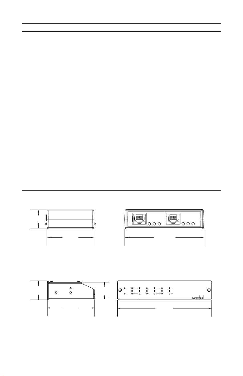
Dimensions ..........................................................................................................1
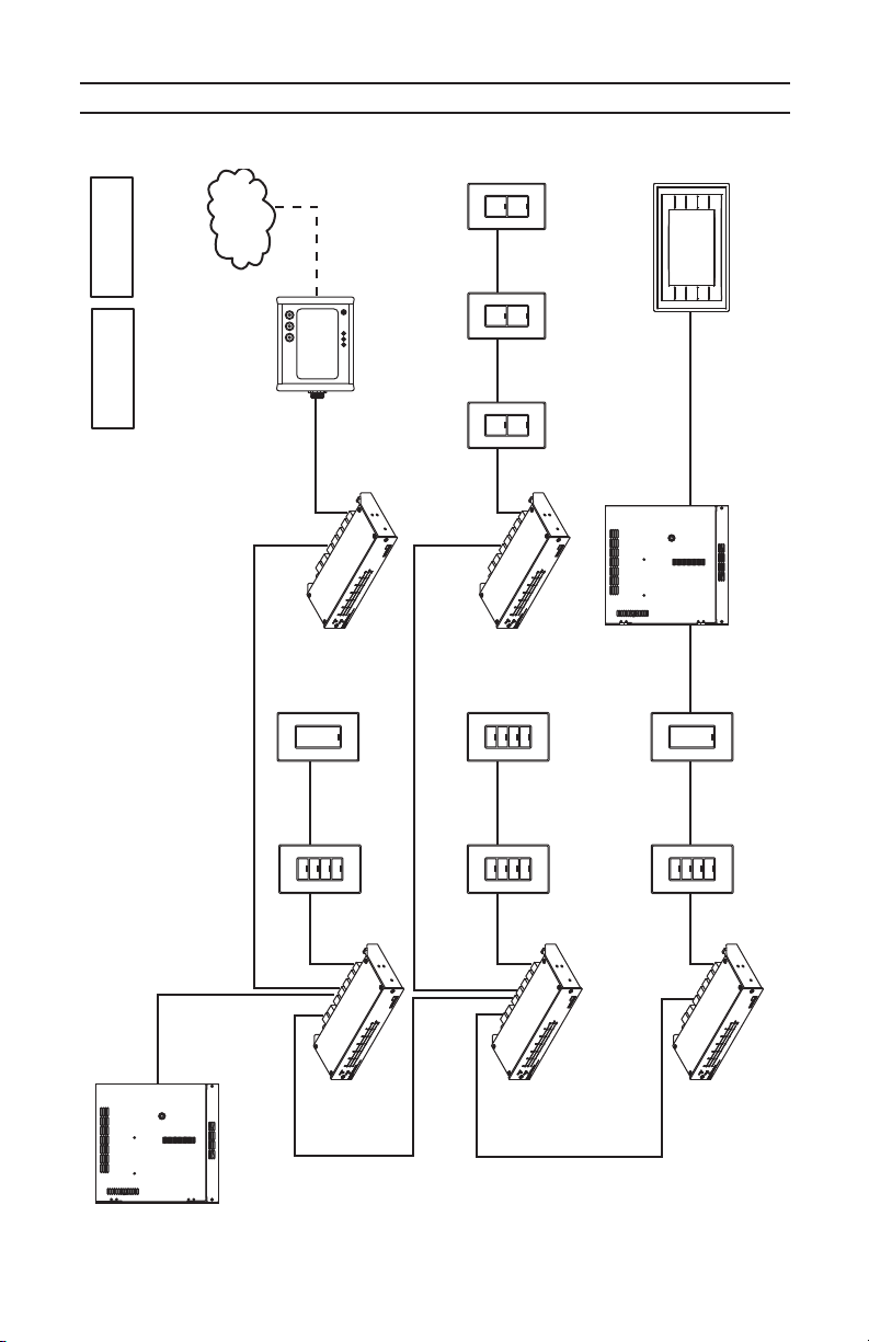
System Diagrams .............................................................................................2-4
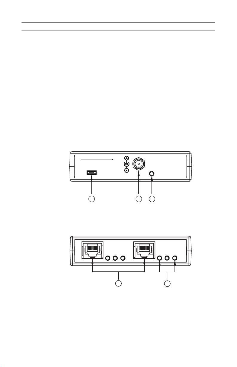
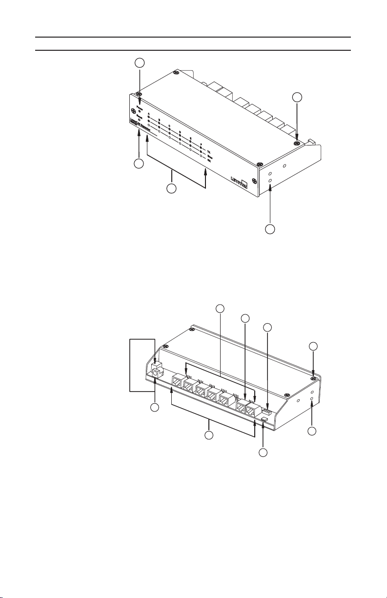
Product Layout .................................................................................................5-6
Installation Pre-requisites...................................................................................7
Installation............................................................................................................7
Jumper Settings ...............................................................................................8-9
LumaCANTM Wiring & Termination ..............................................................10-11
LumaCANTM Wiring Topologies...................................................................11-12
Software Upgrade Process...............................................................................13
Advanced Troubleshooting .............................................................................. 14
Warranty ............................................................................................................. 43
Table des matières
Introduction..........................................................................................................15
Dimensions..........................................................................................................15
Schémas des systèmes..................................................................................16-18
Description des produits.................................................................................19-20
Étapes préalables à l’installation .........................................................................21
Installation ...........................................................................................................21
Cavaliers de configuration..............................................................................22-23
Câblage et terminaisons LumaCANMC ............................................................24-25
Topologies LumaCANMC .................................................................................25-26
Mises à jour logicielles.........................................................................................27
Diagnostic avancé des anomalies....................................................................... 28
Garantie...............................................................................................................43
Tabla de Contenido
Introducción......................................................................................................... 29
Dimensiones........................................................................................................ 29
Diagramas de Sistemas .................................................................................30-32
Diseño del Producto .......................................................................................33-34
Prerrequisitos de Instalación ............................................................................... 35
Instalación ........................................................................................................... 35
Programación de las Interconexiones ............................................................36-37
Cableado y Terminación LumacanTM ..............................................................38-39
Topologías de Cableado LumacanTM ..............................................................39-40
Proceso de Actualización del Software ............................................................... 41
Solución de Problemas........................................................................................ 42
Garantía............................................................................................................... 43

Page 1
INTRODUCTION
Leviton’s 2-Port and 6-Port repeaters are designed to "repeat" LumaCANTM
application data out each port for the purposes of extending network length,
increasing device density, or creating a home-run network topology. Please
refer to typical system diagrams on pages 8 and 9 for example usage.
Quick Facts:
• Input Voltage 2-Port: +12-24Vdc, 40-80mA
• Input Voltage 6-Port: +12-24Vdc, 85-170mA
• LumaCANTM segment
• Topology: Daisy Chain
• Max Length: 1600’
• Wire Type: Cat 6 or better
• Max devices: 110
• Maximum Network with repeaters
• Length: 10,000’ (3,200m)
• Max devices: 254
• Max # of repeaters (depth): 3
• Max # of repeaters (width): 7
Cat. No. NPRPT-002
Side Back
Side Front
DIMENSIONS
CAN 1CAN 2
Tx Rx ErrTx Rx Err
101.09mm
[ 3.98in ]
60.96mm
[ 2.40in ]
24.64mm
[ 0.97in ]
39.29mm
[ 1.55in ]
44.45mm
[ 1.75in ]
109.98mm
[ 4.33in ]
220.35mm
[ 8.67in ]
Power
Reset
LumaCAN Repeater
NPRPT-006
TX
RX
Error
F
EDCBA
Cat. No. NPRPT-006

Page 2
TYPICAL DIAGRAM # 1
2-Port Repeater NPRPT-002 Wiring Diagram
Sector®Net
Sector®Net
Power Supply
Bus Controller
GreenMAX®
Cabinet
GreenMAX®
Cabinet
LumaCANTM
Max 110 Devices
per Segment
Max 250 Devices
per Network
Max Longest
Run - 10,000’
Max Segment
Length Between
Repeaters - 1,600’
T
Sapphire®
To
uch Screen
T = Termination
Switch
LumaCAN Repeater
NPRPT - 002
USB
Power In
+24VDC
LEVITON
LumaCANTM
Repeater
LumaCAN Repeater
NPRPT - 002
USB
Power In
+24VDC
LEVITON
LumaCANTM
Repeater
T
T
T
T
T
GreenMAX®
Cabinet
LumaCANTM
LumaCANTM
LumaCANTM
LumaCANTM
LumaCANTM

Page 3
TYPICAL DIAGRAM # 2
6-Port Repeater NPRPT-006 used with Home-Run Topology
LumaCAN
TM
Repeater
Switch
Sector®Net
Sector®Net
Power Supply
Bus Controller
GreenMAX®
Cabinet
Max 110 Devices
per Segment
Max 250 Devices
per Network
Sapphire®
Touch Screen
T
= Termination
Switch
T
LumaCANTM
GreenMAX®
Cabinet
T
T
T
LumaCANTM
LumaCANTM
LumaCANTM
LumaCANTM
LumaCANTM
T
T
T
T

Page 4
TYPICAL DIAGRAM #3
Multiple 6-Port Repeaters used with Home-Run Topology
LumaCANTM
Repeater
GreenMAX®Cabinet
GreenMAX®Cabinet
LumaCANTM
LumaCANTM
Repeater
LumaCANTM
Repeater
LumaCANTM
Repeater
LumaCANTM
Repeater
Power Supply
Bus Controller
T = Termination
T
T
T
T
T
T
T
T
T
T
T
T
T
T
T
T
T
TT
T
Sector®Net
Sector®Net
Sapphire®
Touch Screen
Max 110 Devices
per Segment
Max 250 Devices
per Network

PRODUCT LAYOUT
1) Micro USB "OTG" Port (Used for software updates).
2) Optional Power Input.
3) Power Indicator (solid when input power is received).
4) LumaCANTM Ports (Internally Terminated).
5) LumaCANTM Indicators.
Err - Red
Rx - Green (blinks when data is received)
Tx - Yellow (blinks when data is transmitted)
NPRPT-002
Back View
CAN 1CAN 2
Tx Rx ErrTx Rx Err
4
5
NPRPT-002
Front View
1 2 3
LumaCAN Repeater
NPRPT - 002
USB
Power In
+24VDC
LEVITON
Heartbeat: Blinks periodically
• Off is indication of internal processor failure.
TX: Transmit
• One provided per port, blinks when transmitting data out that port. Normal
operation is periodic blinking when data is moving on the network.
RX: Receive
• One provided per port, blinks when LumaCANTM data is received on
that port. Normal operation is periodic blinking when data is moving
on the network.
Err: Error
• Blinks when LumaCANTM error is detected, or, when transmit buffer
is full. Normal operation is off.
Power: Solid when input power is received
• Off indicates input power has been lost.
Indicator Key for 2 & 6 Port Repeaters
Page 5

2
3
4
5
1
NPRPT-006
Front View
6
7
8
4
11
10
9
5
NPRPT-006
Back View
1) Power Indicator (solid when input power is received).
2) Reset (push to reset).
3) Port Status Indicators.
4) Mounting holes for adjacent unit when mounted side by side.
5) Cover removal screws (Typical of 4).
6) Power Input Connectors.
7) LumaCANTM Ports.
8) USB "OTG" Port (Used for software updates).
9) Advanced Configuration Switch (normal position is ALL OFF).
10) Termination Switch Port A.
11) Power Routing Jumpers (Typical of 6).
PRODUCT LAYOUT
Page 6

NOTE: To be installed per all appropriate codes per your jurisdiction.
NOTE: For indoor use only.
1. Determine from where repeater will get power, choices are:
• Dedicated power supply (Use Leviton #A0015-000 or equivalent). Power
supply must be a Listed Class 2 power supply or Listed ITE power supply
marked LPS.
• Any LumaCANTM network Port (requires existing LumaCANTM power supply
with enough capacity to power repeater).
2. Determine mounting location:
• 6-Port should be mounted in a 19" EIA rack mount enclosure, or may be
used in a desktop configuration.
• 2-Port may be surface mounted or installed into a field box.
3. Determine where LumaCANTM networks will be terminated:
NOTE: Each end of the network must be terminated. Any mid-point device
must not be terminated. Any other configuration and the network will not
work reliably.
• 2-Port: Both ports are internally terminated and this can not be changed.
• 6-Port: Ports B-F are internally terminated and this can not be changed.
Port A has a termination switch and should be terminated when end-of-run.
4. Network/Power Wiring:
• All wiring is Class 2.
• When architecting the low voltage power system, refer to the "LumaCAN
power considerations white paper" (available at Leviton.com) which
identifies best practices and things to avoid. Additionally, ensure that there
is never multiple power-supplies powering the same segment.
• Do not connect to Ethernet networks. Although LumaCANTM uses RJ-45
connectors, it is not Ethernet and may cause damage to Ethernet systems.
5. Review system requirements from Leviton provided documents or as deduced
from field requirements.
INSTALLATION PRE-REQUISITES
1. Set Jumper positions.
• Refer to diagrams within this document for function.
2. Install device in the enclosure.
• 6-Port rack mount: The device will require one "long" and one "short"
rack mount ear.
NOTE: two devices also may be installed side by side by removing the
top cover, screwing the two devices together using the (2) provided holes,
reinstalling cover, then using only the short rack mounting ears.
• 6-Port desktop: Install provided rubber feet.
• 2-Port: Device may be installed as required by field conditions and allowed
by the authority having jurisdiction. Device is commonly installed "free air",
or in a steel box of appropriate size provided by the contractor.
3. Connect LumaCANTM wires.
• Reference LumaCANTM wiring details for more information.
4. Connect power wires.
INSTALLATION
Page 7

JUMPER SETTINGS NPRPT-002
• Remove cover to access jumpers.
• Jumpers installed at position:
• 1-2 – LumaCANTM #1: will power repeater from LumaCANTM port #1.
• 3-4 – LumaCANTM #2: will power repeater from LumaCANTM port #2.
NOTE: If Jumpers 1-2 & 3-4 are installed, repeater will be powered from
LumaCANTM ports AND pass power through between ports.
NPRPT-002
Power
Routing
Jumper
Heartbeat
Indicator
Setting Jumper positions on Cat. No. NPRPT-002
Page 8

JUMPER SETTINGS NPRPT-006
WARNING: Ensure that only one power supply is providing power to
each segment. Jumpers have been provided to allow you to isolate
power to any part of the network.
Port B-F Jumpers installed on pins:
• 1-2 – Bridge Power between this port and port to right (ex: if jumper
is installed on Ports F 3+4, then power is bridged between Port F &
Port E).
• 2-3 – No function (default configuration).
• 3-4 – Power repeater from power supply on this port.
Port A jumpers installed on pins:
• 1-2 – No function.
• 2-3 – No function (default configuration).
• 3-4 – Power repeater from power supply on this port.
NPRPT-006
Advanced
Configuration
Switch
Port F
Jumper
Port A
Termination
Switch
Port F Port E Port D Port C Port B Port A
4321 4321 4321 4321 4321 4321
Setting Jumper positions on Cat. No. NPRPT-006
Page 9

LumaCANTM WIRING AND TERMINATION
LumaCANTM is Leviton’s proprietary communication protocol for control
systems. Topology for LumaCANTM is daisy-chain and can only support
home-run configurations when Leviton’s LumaCANTM repeaters catalog
numbers NPRPT-002 and NPRPT-006 are used. LumaCANTM wiring
requires Category 6 or better cable (Leviton Cat. No. WIR06-1K or
equivalent). LumaCANTM requires termination at each end of the
LumaCANTM network.
Installation:
1. Terminate end of network cables to Cat. 6 male plugs using the TIA-
568B pin out shown in Figure 1. When terminating a male Cat. 6 plug to
the network cable hold the plug with the clip down and looking at it from
the back to match the Figure 1.
2. Insert the terminated Cat. 6 plugs in to the ports on the Repeater.
3. Terminate all end-of-line devices.
NOTE: Signal termination required at each end-of-line device. DO
NOT terminate midpoint devices.
2-port repeater: NPRPT-002
• Both ports are internally terminated and this can not be changed.
6-port repeater: NPRPT-006
• Ports B-F are internally terminated and this can not be changed
• PortA: must be terminated if end of run. To terminate, push termination
switch towards Port A. The LumaCANTM "Thru" port should be used if
connecting to another repeater. In this case, the termination switch will
be in the un-terminated position, towards port B. Default configuration
is terminated.
Page 10

Page 11
LunaCANTM WIRING TOPOLOGIES
Good Topology: DAISY CHAIN
GreenMAX®Cabinet
Sapphire
®
Touch Screen
Switch Switch
Switch
Sapphire®
Touch Screen
PR3
PR2 PR1 PR4
T568B
TRTTTRRR
++++--
--
12345678
TIA-568B Wiring Standard Chart
Pin Pair # Color
1
2
3
4
5
6
7
2
3
1
3
4
Orange/White
Orange
Blue/White
Green
Green/White
Blue
Brown/White
Brown8
Pinout
There are two major standards for the pinout of RJ-45 connectors. These
two standards are often referenced as TIA-568A and TIA-568B. Although
either is acceptable so long as it is consistent throughout a project, Leviton
requires the use of only the TIA-568B standard. The only difference
between the standards is what color wires terminate to each of the (8)
RJ-45 pins. Per the TIA-568B standard, the pinout for an RJ-45 receptacle
is as follows. When terminating a male RJ-45 plug to the network cable
hold the plug with the clip down and looking at it from the back to match
the figure below.
Figure 1
LumaCANTM WIRING AND TERMINATION CONTINUED

Page 12
LunaCANTM WIRING TOPOLOGIES CONTINUED
Bad Topology: STAR
GreenMAX®
Cabinet
Sapphire®
Touch Screen
Switch
Sapphire®
Touch Screen
Switch
GreenMAX®Cabinet
Sapphire®
Touch Screen
Switch
Sapphire®
Touch Screen
Switch
LumaCANTM
Repeater
Good Topology: HOME-RUN (REPEATER REQUIRED)

Page 13
Software can be updated by connecting a repeater to your computer. Each
repeater has a USB "Micro" connector. Use a cable with USB connector
type "A" on one end and "Micro" connector on the other end. A terminal
program which has the capability to send a file is required to perform the
update process. Tera-Term is recommended. Cygnal "CP2101" drivers also
are required. Both Tera-Term & the CP2101 drivers can be downloaded
from the Leviton website.
Terminal communication settings:
• Baud: 115,200 • Bits: 8
• Stop Bits: 1 • Flow Control: Hardware
• Line Delay: 3ms/Line • Parity: None
Steps:
1. Initiate connection to the repeater through the terminal program. Once
properly communicating to the repeater you should have a command
prompt as follows (You may need to tap Enter):
CLI>
2. Type "update" followed by Enter as follows:
CLI> update
Preparing to update application...
Erasing Application...Complete
Send File...
3. At the "Send File…" prompt, send the firmware file as an ASCII file. You
will see the file echoed to the screen as it is loaded. When transfer is
complete, the repeater will re-boot. Usually, after reboot, you will see
the following:
*******************************************************************************
Leviton CAN Repeater
Firmware version = 0.05
*******************************************************************************
CLI>
If you don’t see the version screen, disconnect the terminal program and
reconnect. Then, at the command prompt type the "Version" command
and you will see the following:
CLI> version
*******************************************************************************
Leviton CAN Repeater
Firmware version = 0.05
*******************************************************************************
SOFTWARE UPGRADE PROCESS

Page 14
The repeaters works with a philosophy of store-and-forward. Each port
maintains a receive buffer and a transmit buffer for every other port. When
data comes in from the network, it is placed into a receive buffer corresponding
to the port that received the data. The repeater will then take the data from the
receive buffer and place it in the transmit buffer of all other ports. Each port
then will transmit data out of the transmit buffer. If a transmit buffer is full for any
port, data in the receive buffer will not be placed into any transmit buffer until
the buffer begins to empty. If the transmit buffer continues to be full causing the
receive buffer to eventually become full, any additional packets will be lost and
consequently packet loss will occur.
Ordinarily, buffer’s will never become full. However, in cases of extreme loading
and poorly architected networks, problems may occur. To troubleshoot buffer
capacity problems, codes are transmitted to the USB port.
By connecting to the USB port and using a terminal program as described in
the section "Software Update", you can observe the following codes being
transmitted by the repeater indicating buffer full messages:
Transmit Buffer Full
Code Appearance: "ATBF"
• The first character, "A", is the port from which data was received
letter (A-F).
• The second character. "T" indicates a transmit buffer is full.
• The third character, "B", indicates the transmit buffer that is full (A-F).
• The fourth character, "F" indicates the buffer is full.
For example, a code of "ATBF" indicates that port A received a message that
is being held in the receive buffer because the transmit buffer for port B is full.
Receive Buffer near capacity
If a transmit buffer remains full for an extended period of time and the
receive buffer begins filling up, a code is transmitted once the receive
buffer is filled to 90% or above as follows:
Code Appearance: "FR+90"
• The first character, "F", is the receive port letter ( A-F).
• The second character, "R" indicates a receive buffer.
• The third character is a "+" sign indicating at or above.
• The fourth and fifth characters "90" indicate a percentage. At the
time of this writing, only 90 would ever be displayed.
For example, a code of "FR+90" indicates that port F’s receive buffer is
90% (or greater) full.
Receive Buffer Full
Code Appearance: "BRF"
• The first character is the receive port letter (A-F).
• The second character, "R", indicates that it’s a receive buffer.
• The third character, "F", indicates the buffer is full.
For example, a code of "BRF" indicates that port B’s receive buffer is full.
ADVANCED TROUBLESHOOTING

Page 15
INTRODUCTION
Les répéteurs à deux et à six ports de Leviton sont conçus pour retransmettre les
données LumaCANMC de façon à étendre les réseaux, à augmenter la densité de
dispositifs ou à créer une topologie de parcours autonomes. On peut se reporter
aux schémas des pages 16, 17 et 18 pour voir des exemples d’usage.
Brève description :
• Tension d’entrée (modèles à 2 ports) : +12-24 V c.c., 40-80 mA
• Tension d’entrée (modèles à 6 ports) : +12-24 V c.c., 85-170 mA
• Segments LumaCANMC
• Topologie : en cascade
• Longueur maximale : 486,7 m
• Type de fils : catégorie 6 ou mieux
• Nombre maximal de dispositifs : 110
• Dimensions maximales des réseaux dotés de répéteurs
• Longueur : 10 000 pi (3 200 m)
• Nombre maximal de dispositifs : 254
• Nombre maximal de répéteurs (profondeur) : 3
• Nombre maximal de répéteurs (largeur) : 7
N° de cat. NPRPT-002
Côté Arrière
Côté Avant
DIMENSIONS
CAN 1CAN 2
Tx Rx ErrTx Rx Err
101.09mm
[ 3.98 po ]
60.96mm
[ 2.40 po ]
24.64mm
[ 0.97 po ]
39.29mm
[ 1.55 po ]
44.45mm
[ 1.75 po ]
109.98mm
[ 4.33 po ]
220.35mm
[ 8.67 po ]
Power
Reset
LumaCAN Repeater
NPRPT-006
TX
RX
Error
F
EDCBA
N° de cat. NPRPT-006

Page 16
SCHÉMA TYPE 1
Répéteur à deux ports (NPRPT-002)
SectorMD Net
SectorMD Net
Contrôleur de bus/bloc
d’alimentation
GreenMAX®
Cabinet
Armoire
GreenMAX
MD
LumaCANMC
Maximum de 110
dispositifs par
segment
Maximum de 250
dispositifs par
réseau
Parcours maximal
de 10 000 pi
(3048m)
Longueur maximale
des segments entre
répéteurs de 1 600 pi
(488m)
T
Écran tactil
e
SapphireMD
T = Te rminaison
Commande
LumaCAN Repeater
NPRPT - 002
USB
Power In
+24VDC
LEVITON
Répéteur
LumaCANMC
LumaCAN Repeater
NPRPT - 002
USB
Power In
+24VDC
LEVITON
Répéteur
LumaCANMC
T
T
T
T
T
Armoire
GreenMAX
MD
LumaCANMC
LumaCANMC
LumaCANMC
LumaCANMC
LumaCANMC

Page 17
SCHÉMA TYPE 2
Un répéteur à six ports (NPRPT-006) dans une
topologie de parcours autonomes
Répéteur
LumaCANMC
Commande
SectorMD Net
SectorMD Net
Contrôleur de bus/bloc
d’alimentation
Armoire
GreenMAXMD
Maximum de 110
dispositifs par
segment
Maximum de 250
dispositifs par
réseau
Écran tactile
SapphireMD
T = Te rminaison
Commande
T
LumaCANMC
Armoire
GreenMAXMD
T
T
T
LumaCANMC
LumaCANMC
LumaCANMC
LumaCANMC
LumaCANMC
T
T
T
T
This manual suits for next models
1
Table of contents
Languages:
Other Leviton Repeater manuals