Lexing LX-LD105P-ADS User manual

Power source: 100-240V/AC, 50/60Hz
Rated LED: 15W Max.(AC)
8W Max.(DC)
Charging power: 7W Max.(light off )
3W Max.(light on )
HF system: 5.8GHz
Battery: 7.4V / 2000mAH lithium battery
7.4V / 1600mAH lithium battery
Continuous illumination time: 180min/ 120min
Transmission power: <0.3mW
Time setting: 6sec to 12min (adjustable)
Light-control: 10-2000LUX(adjustable)
Detection range: 1-10m (radii.) (adjustable)
(Installation height: 2.5m)
Detection angle: 360°
Luminous flux: 1000lm(AC) 330lm(DC) (warm white)
Installation height: 2.5-3.5m (ceiling mount)
Working temperature: -20~+55℃
Lamp part
LED quantity: 96PCS
LED specifications: T5050
Summary
LX-LD105P-ADS Microwave Sensor Lamp Instruction
Specifications
Name of each part
IP 54
Microwave Sensor Lamp
1X
Instruction
1X
4X
4X
Quantity
Packing list in
Φ6 Plastic Expansion
4x30 Screw
This is a newly designed intelligent ceiling mount microwave sensor LED lamp, with the
extra function of power supply in emergency. The lighting is auto-managed by AC direct
power or battery backup, that is, when power failure, the battery backup will be
responsible for the power supply of 8 watt. When light on, the luminous flux will be more
than 800 lm, equivalent to twice that of 60 watt incandescent lamp(≈400lm). The battery
backup can continuously supply power for more than 3hours / 2 hours or even more in
the sensor energy-saving mode. It is widely applied in the corridor, washing room,
elevator lobby etc.
This product is designed with two configurations: one is the sensor lamp with the
function of supplying power in emergency and the other one is the intelligent sensor
lamp without the emergency function. You can make purchase according to the practical
need. But in most cases, it is necessary and wise to choose the former one, for that the
occasional power outage will cause trouble, or even danger.
Microwave sensor
Threading hole
Threading hole
Battery
Mounting holes
Mounting holes
Mounting holes
Wiring
Knob
Mounting holes
The switch controlling the battery
320mm 111mm
Use high quality PC lampshade.Strengthen the flexible refraction
of light.And its function of anti-ultraviolet makes the shade not
easy to turn yellow and be broken.
LED lamp consumes power 80% less
than incandescent lamp and 50% less
than fluorescent lamp.
PC lampshade
Lampshade
fixed hole
Lampshade
fixed hole
Lampshade
fixed hole

Emergency function
Spectrogram
60 watt incandescent lamp(≈400lm)
1 2 3
安全出口
EXIT
In case of sudden blackout, our products can still work properly
In case of sudden blackout and there is nobody in the surrounding After the blackout, people evacuate from the elevator
* Installed in the elevator, when power fails, it still supports lighting for the trapped.
LX-LD-105P-ADS (AC 1000lm) (warm white)
LX-LD-105P-ADS (DC 330lm) (warm white)
1 2 3
安全出口
EXIT
When light on, the luminous flux will be more
than 800 lm, equivalent to twice that of 60
watt incandescent lamp(≈400lm).
Fig.1

Fig.2
Detection range setting (sensitivity)
Detection range is the term used to escribe the radii of the roughly circle casting on the
ground when installed at the height of 2.5 m. To turn the knob fully anti-clockwise is the
minimum range(approx.1m radii), fully clockwise is the maximum(approx.10m radii).
NOTE: the above detection range is gained in the case of a person who is between 1.6m~1.7m
tall with middle figure and moves at a speed of 1.0~1.5m/sec. if person’s stature, figure and
moving speed change, the detection range will also change.
In different cases, the sensitivity of the lights has certain deviation.
Sensor information
Function
The switch controlling the battery
Sensing distance adjustment range Sensing angle adjustment rangeHeight of installation2.5~3.5M
2.5-3.5m
Min:1m Min:1m
Max:10m
Max:10m
360º
Notice: when using this product, please adjust the sensitivity (detection range) to an
appropriate value but the maximum to avoid the abnormal reaction caused by the easy
detection of the wrong motion by the blowing leaves & curtains, small animals or the
interference of power grid & electrical equipment. All the above mentioned will lead to the
error reaction. When the product does not work normally, please try to lower the sensitivity
appropriately, and then test it.
This switch is to control the battery connection. To avoid power-consumption in transit or in storage, we preset
the switch to OFF, that is, the battery is not connected. Before installation, you should set the switch to ON to
make sure that the battery is well connected to achieve the power-supply in emergency. When power failure, the
battery can supply the sensor lamp with the power to maintain lighting, in this case, the sensor lamp will be
constantly on.
The switch controlling
the battery

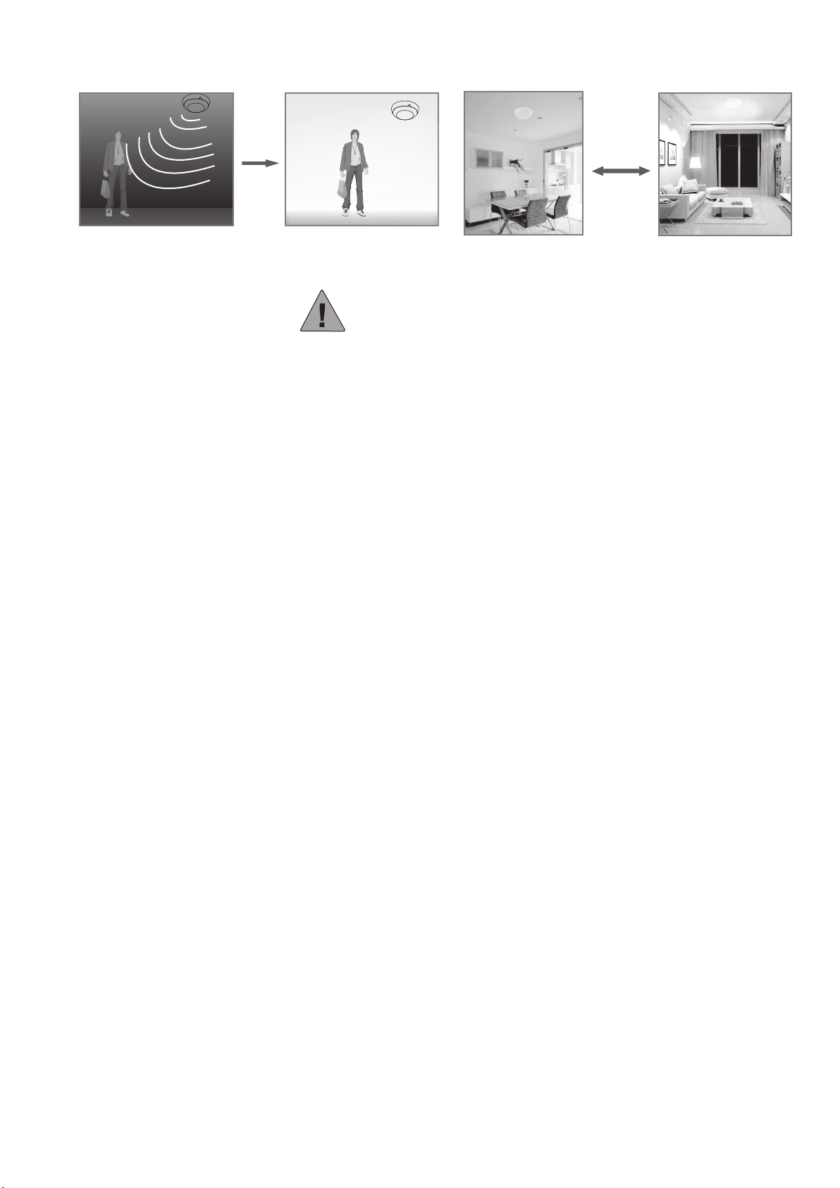
NOTE:When the light be auto off,it will take 1 second before the sensor is ready to detect
another movement,that is,only signal detected 1 seconds later can the light be auto-on.
It is mainly for the adjustment of the delay time from the moment the signal detected and light
auto-on till the light auto-off. You can define the delay time to your practical need. But you’d
better lower the delay time for the sake of energy saving, since the microwave sensor has the
function of continuous sensing, that is, any movement detected before the delay time
elapses will re-start the timer and the light will keep on only if there is human in the detection
range. Thus,when performing installation test,we suggest you keep the movement from the
detection range to avoid the delay time multiplying.
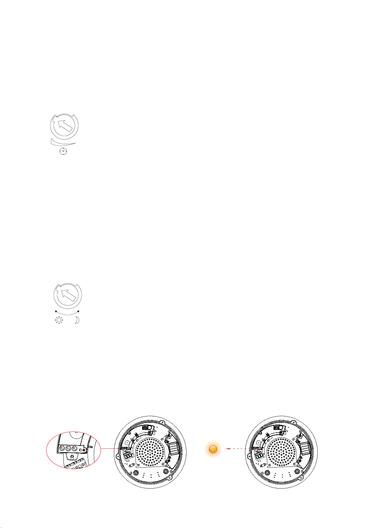
Time setting
It can be defined from 6 seconds(turn fully anti-clockwise) to 12minutes(turn fully
clockwise). Any movement detected before this time elapses will re-start the timer. It is
recommended to select the shortest time for adjusting the detection range and for
performing the walk test.
Microwave can be reflected by the metal and the detection range will be multiplied,the
sensitivity increased.For those installed inside the steel-structure buildings, you'd better
lower the sensitivity to the appropriate. Products should be installed more than 4 meters one
from another, otherwise the interference among them will cause error action.
The LUX knob is used for adjusting the ambient illumination,that is,
customers can define the appropriate value to their need.
Installation location:
1、There is an optical sensor inside the lamp(as fig.3),during the installation,it should be
turned to where the sunshine is sufficient.At the same time,it should avoid other light
sources,which will influence the judgement of optical sensor to the ambient illumination.
2、For different people have different demand on installation location and ambient
illumination,the LUX value differs.It will take times to adjust the value to your need.
NOTE: Turn the optical sensor to where the sunshine is sufficient(as fig.4).
Light-control setting
It can be defined in the range of 10-2000 LUX. To turn the knob fully anti-clockwise is
about 10 lux,fully clockwise is about 2000 lux.When adjusting the detection zone and
performing the walk test in daylight,you should turn the knob fully clockwise.
Fig.3 Fig.4

Note: Please don’t adjust the three functional buttons to excess. That is because the three
functional buttons were connected to the components directly, there is a small stopper in
each of the three components, when you adjust the buttons from start to end, the excessive
turn will damage the stopper,and lead to the 360°non-stop turn around. The adjust range
limit is 270°, please do pay attention to this.
Pencil Electric drill Hammer Screwdriver
Note:Please bring the following tools
Warning!
Procedure of installation
1. Please keep it away from the children when installation.
2. Please avoid to be installed where the temperature or humidity is high.
3. Please cut off the power before installation.
Fig.6 Fig.7
• Step3 Put the base of the product on the ceiling to make the drilling mark (as Fig.6)
• Step4 Install the product on the place where you marked (as Fig.7)
Products should be installed more than 4 meters one from the other,otherwise the interference among
them will cause error action.
AB
Fig.5
• Step1 Turn off the screw to take down the lampshade
(as follow: the product should be separated into two parts as A and B)
• Step2 Turn the knobs to the ideal conditions
(Please define the settings as per the above FUNCTION part mentioned.).
• Step5 Knock the plastic expansion screw into the hole which you drill (as Fig.8)
• Step6 Put the power line through the line hole to connect on the wiring (as Fig.9)
Fig.8 Fig.9
Ceiling
40mm
10mm

• Step7 Fix the base of the product on the selected place with the screws (as Fig.10)
Fig.10
Concrete ceiling
• Step8 Fix the PC lampshade on the base with the screws (as Fig.11)
Fig.11
Note:
the high-frequency output of this
sensor is<0.3mW- that is just one 3300 of
the transmission power of a mobile phone
or the output of a microwave oven.
Transmission power: <0.3mW
th
Fault and the solution
The load fails to work.
Light-illumination is set incorrectly.Adjust the setting of the load.
Change the load.
Turn the power on.
Check the settings of the
detection area.
Re-adjust the installation place.
Check the settings of the
detection area.
Check the settings of the
detection area.
The load is broken.
The power is off.
There is a continuous signal in the region of the detection.
Moving signal is detected by the sensor (movement
behind the wall, the movement of small objects, etc.)
The lamp isn't installed well so that sensor fails to
detect reliable signals.
The motion speed is too fast or the defined detection
area is too small.
Fault Failure cause Solution
The load works all the time.
The load works when there is
no motion signal detected.
The load fails to work when
there is motion signal detected.
* When power failure, the battery can supply the sensor lamp with the power to maintain lighting, in this case, the sensor lamp
will be constantly on.

Induction of human movement Since entering lighting condition
Application
Warning!
• Please confirm with profession installation.
• Please cut off power supply before installation and removal operations.
• Make sure that you have cut off the power for safety purposes.
• Improper operation caused losses, the manufacturer does not undertake any responsibility.
1.The LEDS in serial can function when all the seals installed in place.
2.Please don’t remove or connect with other lamp when powered on.
3.When the LEDS in serial are damaged ,you need experienced technician to repair using
the same rating LEDS.
We are committed to promoting the product quality and reliability, however, all the electronic
components have certain probabilities to become ineffective, which will cause some troubles.
When designing, we have paid attention to redundant designs and adopted safety quota to
avoid any troubles.
This instruction, without our permission, should not be copied for any other purposes.
Table of contents
Other Lexing Lighting Equipment manuals
Popular Lighting Equipment manuals by other brands

Ryger
Ryger Defender DMX Range instruction manual

Commercial Electric
Commercial Electric VICTORIA Series Use and care guide

Prilux
Prilux ecTUBE T8 Glass NR basic instruction manual

Good Earth Lighting
Good Earth Lighting G9712L-T5-WHESI quick start guide

König Electronic
König Electronic KN-SF200 manual

unios
unios Zeron Series quick start guide

Traxon Technologies
Traxon Technologies e:cue LIGHTDRIVE+ WiFi Configuration guide

Chauvet
Chauvet Colorado 1-Quad Tour user manual

Chauvet
Chauvet COLORado PXL Bar 16 user manual

WE-EF
WE-EF RAIL66 Series Installation and maintenance instructions

Robe
Robe CitySource 96 user manual

Chauvet
Chauvet LEDsplash 152B user manual