~
~~
IIJ'~
r-
--~
--------------~
----
----------------------------------------
-
LEYBOLD
SECTION
1
INTRODUCTION
This
manual
contains
all
of the information
that
you
need
to
safely
install,
start,
operate, maintain, troubleshoot,
and
order
parts
for
your
OF-lOOO
oil
filtering
system.
The
OF-IOOO
oil
filtering
system extends
the
life
of
the
vacuum
oil
and
of
the
vacuum
pump
by
removing contaminants
and
heat
from
the
oil.
It
can
be
used
with
TRIVAC
"A"
pumps.
With
minor
modifications,
you
can
also
use
it
with E
and
OK
series
rotary
piston
pumps
(see
Appendix A).
Aluminum
oxide,
particulate,
Fullers
Earth
and
hydroph
ilic
filtering
elements
are
available
for
use
in
the
OF-1000
. See S
ection
3
for
a
detailed
description
of
the
OF-1000
and
Sectio
n
3.3
for
information
on
selecting
the
correct
filter
element fo r your
application.
There are
two
model
s of the
OF-lOOO:
1) a
single-canister
housing
model
and
2)
a dual-canis
ter
model. There are three versions of each
of
these
two
models: 1) a
st
andard version,
2)
a version prepared for
perfluoropolyether
oil,
and
3)
a coated
corrosive-series
version prepared
for
perfluoropolyether
oil.
The
coated version
is
referred
to
as the
OF-IOOOC.
Unless otherwise noted,
all
references
to
the
OF-1000
in
this
manual
apply to
all
three
versions of the oil
filtering
system.
Check
the nameplate
on
the
OF-1000
pan
to determine
which
version
you
have.
The
following
lists
the
part
number
for each version.
Single-Canis
ter
Model
Standard V
ersi
on
Version Prepared for Perf1uoropo1yether
OF-IOOOC
Coated Version Prepared for
Perflu
cr
opo
1
yether
Dual-Canister
Model
Standard V
ersi
on
Version Prepared for Perf1uoropolyether
OF-IOOOC
Coated Version Prepared for
P
erfluor
opo
1
yether
Part
Number
898550
898551
898561
Part
Number
898552
898553
898554
The
top of the
cove
r nut
is
painted
brown
on
the
OF-1000C
versions to
make
it
easy to
identify
.
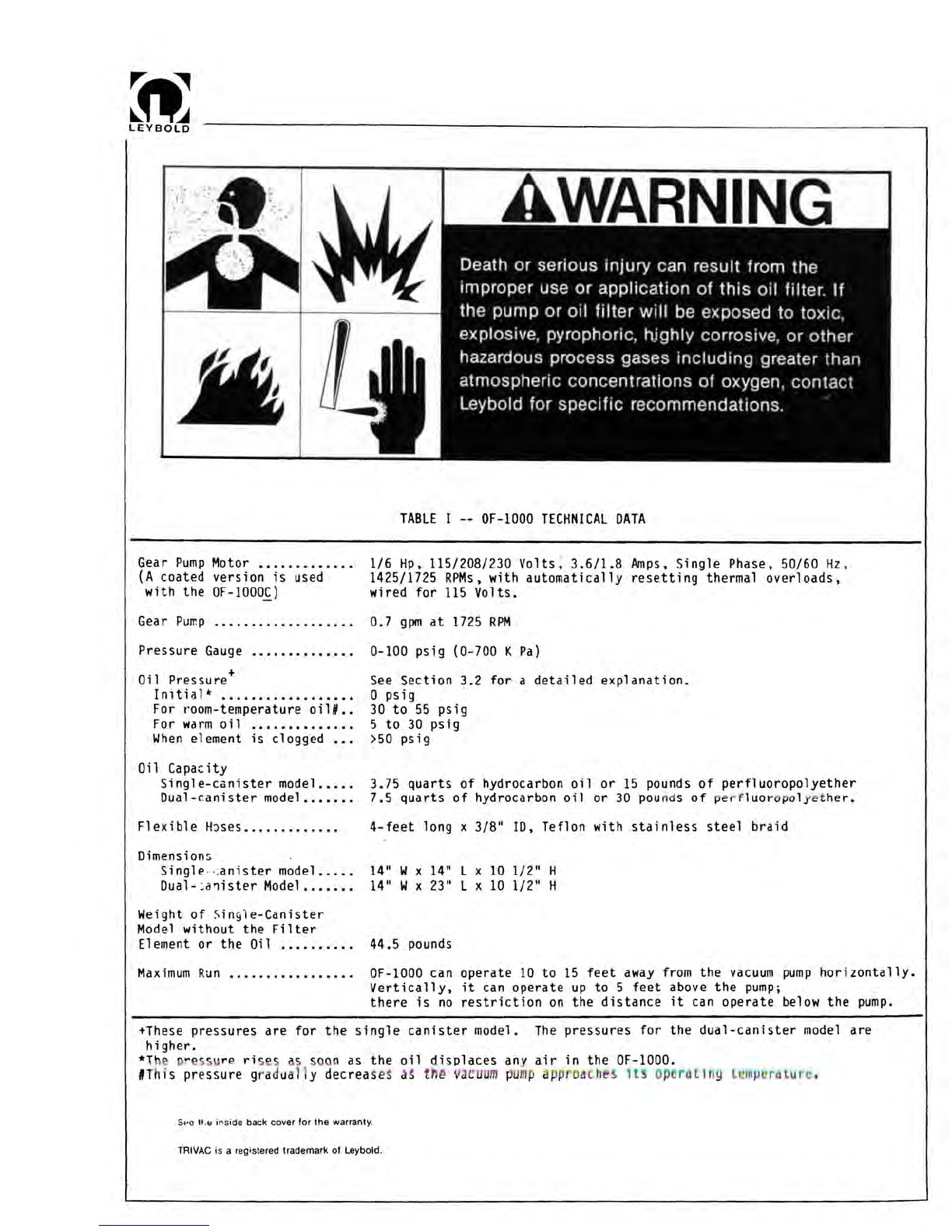
"WARNING
" statements are used in
this
manual
to prevent injury to
personnel ;
"CAUTION
" statements are used to prevent
damage
to equipment;
"NOTES"
contain hel pful information.
1