LF Illumination VF100 Series User manual

Butterfly Mounting (Commercial):
Step 1. Fixture comes equipped with Universal BUTTERFLY
MOUNTING BRACKETS and take common 1” or 1-1/2” Black
Iron or Galvanized MOUNTING CHANNELS (Supplied By Others).
Step 2. POSITION FIXTURE so the MOUNTING CHANNELS lie on
top of ceiling runners.
Step 3. Fasten MOUNTING CHANNELS securely to the ceiling
runners with wire tie downs.
Step 4. Secure MOUNTING CHANNELS to the UNIVERSAL
BUTTERFLY MOUNTING BRACKETS with wire tire downs.
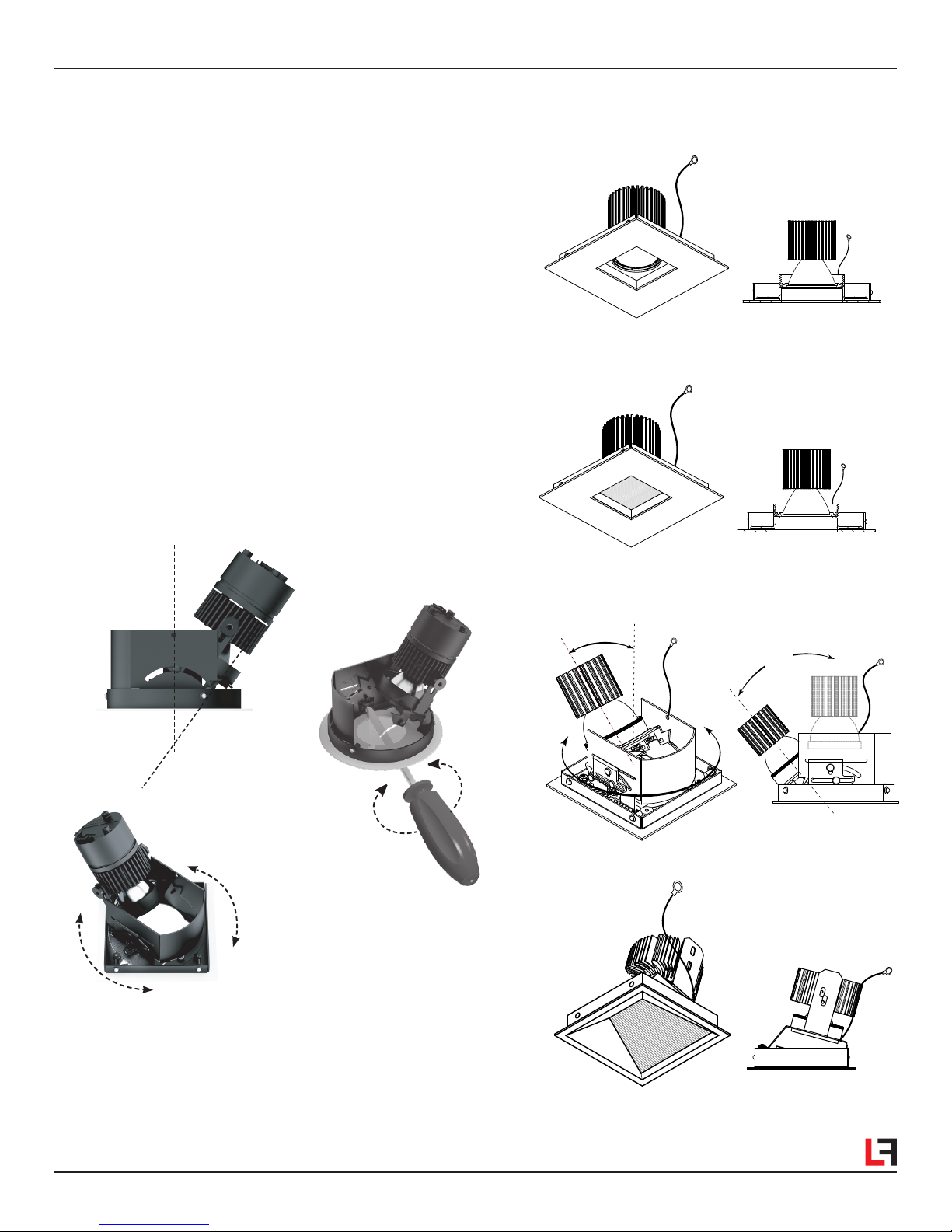
Step 5. ADJUST ELEVATION OF FIXTURE so that the surface of
the PERFORATED HOUSING PLATE SITS FLUSH with the top of
the finished ceiling surface. Fine adjustments can be made by
loosening the two (2) 1/4” HEX SCREWS on both UNIVERSAL
BUTTERFLY MOUNTING BRACKETS and set accordingly Fig 1.
See FINE CEILING ADJUSTMENT
Fig 4
.
VF100 Series Mini and Small
SQUARE TRIMMED FIXTURE
INSTALLATION INSTRUCTIONS
* Risk of fire or electric shock.
* Disconnect all power before installing or servicing.
* Installation Instructions for qualified electricians only.
* Install per National Electrical Code and local regulations.
* Read Installation Instructions completely before installation.
* Failure to follow Installation Instructions may void warranties.
THIS PRODUCT MUST BE INSTALLED IN
ACCORDANCE WITH THE APPLICABLE
INSTALLATION CODE BY A PERSON
FAMILIAR WITH THE CONSTRUCTION AND
OPERATION OF THE PRODUCT AND THE
HAZARDS INVOLVED.
C US
®
Warnings:
It is IMPORTANT TO READ instruction sheet completely before installation
Joist Installation:
Includes Heavy-Duty L-Bars™ hanger bar system LF# LBARS4PK
Step 1. Extend HANGER BARS to fit between joist and
attach to joist or frame member using appropriate hardware for
material. See Fig 2, Detail 2A.
Step 2. ADJUST ELEVATION OF FIXTURE so that the surface of
the PERFORATED HOUSING PLATE SITS FLUSH with the top of
the finished ceiling surface. See Fig 1.
Step 3. Position housing horizontally by sliding on hanger bars.
Secure housing in position using wire tie downs. See Fig 2.
Pre-Installation Note: The trim and housing are packaged and shipped in separate cartons. Set the trim unit aside in a clean
and undamaging environment. The trim unit will be put in place after housing / ceiling installation. For joist installations or where wiring
access to housing is limited, it is advised to pre-wire the housing with leads before installation.
Alternate Mounting
Suspension Tabs
Mounting
Channel
(By others)
Universal Butterfly
Mounting Bracket
(2) 1/4” Hex Screw
Trim Collar
Perforated
Plaster Frame
Finished
Ceiling Surface
FIGURE 1
Hanger Bars
Detail 2A
Adjustable
Plaster Frame with
Breakaway Feature
Breakaway Plaster Frame Length
for Closer Edge Positioning
Alternate Mounting
Suspension Tabs
Joist Joist
FIGURE 2

VF100 Series
SQUARE TRIMMED FIXTURE
Added Feature
45° Rotatable
Trim
Connection
Power Supply
Line
Round Trim w/Snap-in
Spring Loaded Ball Plungers
Trim Safety Cable
Housing Safety Cable
Square Trim Housing
Square Rotatable
Collar Plate
Suspension tabs
TRIMMED INSTALLATION ASSEMBLY
INSTALLATION INSTRUCTIONS
FIGURE 5
FINE CEILING ADJUSTMENT
FIGURE 4
1/2”
5/8”
3/4”
1”
Four
locking
height
positions
Trim
Aperture
Wall
Housing
Adjustable
Plaster Frame
Drywall screw.
Only use screw if
adjustable plaster frame
is set to proper height.
Adjustable
Frame Tabs
Drywall Ceiling
Patch over screw head.
CEILING INSTALLATION:
Step 1. PLASTER FRAME
FINE CEILING ADJUSTMENT accommodates
for 1/2”, 5/8”, 3/4” and 1” ceiling thickness. See Fig 4.
Step 2. CUT A CLEAN SQUARE OPENING in the CEILING MATERIAL to
fit the trim collar. Install the ceiling material below housing as shown in
Fig 1. Ceiling Cut-Out - 4.25” Square.
ELECTRICAL CONNECTION:
The housing features an easy access electrical compartment
for simplified field wiring installation.
DO NOT modify the factory wiring settings as it may cause
the luminaire to malfunction.
Notes: The cover panel knockouts will accept 3/4˝ trade size
fittings. Review fixture labeling to make sure it is rated for the
voltage installation being used.
Step 1. Provide electrical service according to the “National
Electrical Code” or your local electrical regulations from a
suitable junction box. Supply wire insulation must be rated for
at least 90°C.
Step 2. Remove electrical compartment cover panel Fig 3.
Step 3. Remove appropriate knockout and connect conduit
with proper connector (not included).
Step 4. 120V or 277V AC Supply: Connect white to white,
black to black and green (from electrical service) to the green
copper wire located in the junction box. Make sure no bare
wires are exposed outside wire connectors.
Step 5. Place all connections and excess wiring into the
electrical compartment and reattach cover panel Fig 3.
FIGURE 3
Electrical Compartment
Power Supply
Cover
Panel
Knockouts
ELECTRICAL COMPARTMENT
FIGURE 3
It is IMPORTANT TO READ instruction sheet completely before installation

FIXED
ADJUSTABLE
FIXED SHOWER
WALL WASH
TRIMMED FIXTURE APPLICATIONS:
Tilt
TRIM INSTALLATION - FASTENING TO COLLAR:
Step 1.
FOR ALL TRIM APPLICATIONS. Secure safety cable on
the trimmed fixture to the safety cable in the housing using the
clasp provided.
Step 2.
Connect the power supply line from the housing to the
trim using connections provided.
Step 3.
Push the trim into the housing collar. The spring loaded
ball plungers will snap into place See Fig 5.
ADJUSTABLE HOT AIMING
The VF100 adjustable fixtures are offered in trim or trimless versions.
The flat trims can adjust from 0° to 40° while the beveled may be
adjusted from 0° to 45°. Both styles include HOT AIMING capability to
enable the fixture to be aimed with an ordinary Phillips screwdriver
while it is powered on Fig 6.
0º - 40º
Flat Trims
360º+ Locking
Rotationon
Square Fixtures
0º - 45º
Beveled Trims
Place screwdriver in through the apperture.
Turn the adjusting screw located on the
inner sidewall to desired aiming position.
Hot Aiming with
Phillips screwdriver
Both Round & Square
Apertures
See back panel for LED WARNINGS
FIGURE 6
It is IMPORTANT TO READ instruction sheet completely before installation

www.lfillumination.com
HEADQUARTERS
9200 Deering Avenue
Chatsworth CA 91311
Telephone: 818-885-1335
Toll Free: 855-885-1335
Fax: 818-576-1335
©2017 LF ILLUMINATION LLC
We reserve the right to change or
withdraw specifications without prior notice. VFS-1BA-T 111517
VF100 Series
SQUARE TRIMMED FIXTURE
LED WARNING:
LED’s are sensitive electronic components and cannot be
subjected to the excessive dust present during the
construction process. Under no circumstances should the
LED luminaires be used as work lights during the
construction process as this will cause irreparably damage
to LED.
Only compressed air may be used to blow the dust from
the components. The LED and heatsink may not be cleaned
with any sort of a liquid or solvent. The COB array may
not be touched or dusted. LEDs are ESD (Electro Static
Discharge) sensitive devices that can be easily damaged
if the proper ESD mitigating steps are not taken. LEDs are
sensitive to mechanical damage, caution must be taken to
avoid touching the LEDs. ESD or mechanical damage voids
all warranties.
CAUTION:
ALL WORK MUST BE DONE WITH CIRCUIT OFF AND
COMPONENTS SHOULD NOT BE INSTALLED WHEN
ENERGIZED.
It is IMPORTANT TO READ instruction sheet completely before installation
Other LF Illumination Lighting Equipment manuals
Popular Lighting Equipment manuals by other brands

EasyPro
EasyPro AquaShine WFL3 Instructions for Operation, Safety, Warranty

CARVIN
CARVIN STARBRIGHT941302800 series installation guide

Laserworld
Laserworld Pro-6000 RGB user manual

Renkforce
Renkforce 1342099 operating instructions

ViSAGE
ViSAGE VIS130 Hypermove user manual

American DJ
American DJ MULTI-STAR II User instruction

Harvia
Harvia sentiotec TUBE LED RGBW installation guide

p-light
p-light Maxi Installation and instructions for use

involight
involight PaintBar HEX12P user manual

Equinox Systems
Equinox Systems EQLED65 Giga Bar System user manual

iGuzzini
iGuzzini LINEALUCE MINI 37R SURFACE manual

Dextra
Dextra HBE3 M3 LE3 Installation leaflet