LF DuraWorx DWX0865-D User manual

1
Questions, problems, missing parts? Before returning to your retailer, call our customer
service department at 1-800-867-6763, 9 a.m. - 4 p.m., CST, Monday-Friday.
ITEM # 0204632
MODEL # DWX0865-D
HEAVY DUTY GARDEN
DUMP CART
Español p.12
®
Durawox® is a registered trademark
of LF, LLC. All Rights Reserved.

PACKAGE CONTENTS
Part Description Quantity
Tray 1
Dump Lock Assembly 1
Rear Strut 2
Rear Frame 1
Rear Axle Assembly 1
Front Frame 1
Front Strut 2
Front Axle Assembly 1
Wheel 4
Handle 1
Accessory Tray 1
Hardware Kit (see Hardware Contents for details) 1
A
B
C
D
E
F
G
H
I
J
K
L
A
B
C
C
D
E
F
G
H
I
I
I
I
J
L
K
2

HARDWARE CONTENTS
Quantity
Picture
(Shown to size)
M8 x 20mm
Hex Bolt
2
Part
M8 x 20mm
Truss Head
Bolt
4
4Wheel Spacer
5
M8 x 30mm
Truss Head
Bolt
WARNINGS AND CAUTIONS
WARNING:
• Read, understand and follow ALL instructions before using this product.
• Do not exceed the overall maximum load capacity of 1,200 lbs. or the maximum dumping load
capacity of 500 lbs.
The weight rating is based on an evenly distributed load.
• Do not allow children to use the cart without supervision. This cart is not a toy.
• Do not use this cart for transporting passengers.
• This cart is not intended for highway use.
• Do not exceed 5 mph.
CAUTION:
• Distribute the load evenly over the surface of the tray.
• Do not load items on the top edges of the tray.
• If any parts become damaged, broken or misplaced, do not use the cart until replacement
parts have been obtained.
• Do not use the cart on surfaces or for transporting objects that can cause damage to the
pneumatic tires or tubes. Do not inflate the tires to more than 30 PSI (2.07 BAR).
• It is recommended that the cart be inspected for damage before each use.
• KEEP THESE INSTRUCTIONS FOR FURTHER REFERENCE.
AA
DD
HH
20
M8 Flat
Washer
I I
2
M6 x 20
Shoulder Bolt
JJ
CC
Description Quantity
Picture
(Shown to size)
M8 Lock Nut 20
Part
FF
Description
M8 x 20mm
Carriage Bolt
8
BB
M12 Flat Washer 4
KK
LL
M6 Lock Nut 2
MM
M6 Flat Washer 2
M12 Lock Nut 4
GG
1M8 x 60mm
Round
Head Bolt
EE
3

ASSEMBLY INSTRUCTIONS
Fig. 1
Hardware Used
Note: During each step of assembly, assemble
all hardware and hand tighten. Once all the
hardware is installed for that particular step,
tighten all the hardware.
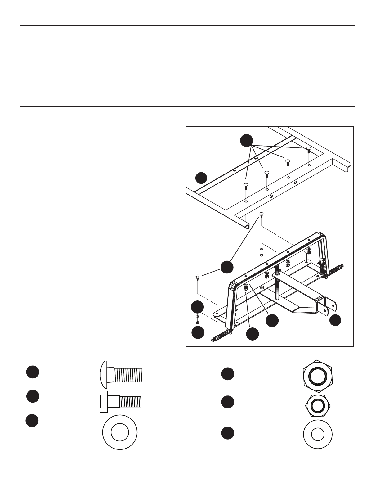
1. Attach the front axle assembly (H) to the
front frame (F) using four M8 x 20mm
carriage bolts (DD), four M8 lock nuts (JJ),
and four M8 washers (GG).
Attach the outer ends of the steering linkage
using two M6 x 20mm shoulder bolts (FF),
M6 lock nuts (LL), and M6 washers (MM),
as shown in Fig. 1.
Hand tighten all bolts until after Step 2.
F
H
PREPARATION
Before beginning assembly of product, make sure all parts are present. Compare parts with
package contents list and diagram above. If any part is missing or damaged, do not attempt to
assemble the product. Contact customer service for replacement parts.
Estimated Assembly Time: 30 minutes
Tools Required for Assembly: Flathead screwdriver, Phillips screwdriver and socket set
(or two adjustable wrenches). (tools not included)
4
DD
DD
x 4
M8 Flat
Washer
JJ
JJ
M8 Lock Nut x 4
M8 x 20mm
Carriage Bolt
x 4
LL
LL
M6 Lock Nut x 2
MM
MM
M6 Flat Washer x 2
GG
GG
x 2
M6 x 20
Shoulder Bolt
FF
FF

ASSEMBLY INSTRUCTIONS
Fig. 2
Hardware Used
2. Attach the front struts (G) to connect the
the front axle assembly (H) to the front
frame (F) using four M8 x 20mm carriage
bolts (DD), using four M8 lock nuts (JJ), and
four M8 washers (GG), as shown in Fig. 2.
Tighten all bolts from Step 1 and
Step 2 securely.
Fig. 3
G
G
H
F
5
DD
DD
DD
DD
x 4
M8 Flat
Washer
JJ
JJ
JJ
M8 Lock Nut x 4
M8 x 20mm
Carriage Bolt
x 4
GG
GG
GG
3. Slide the rear struts (C) onto the
ends of the rear axle assembly (E),
as shown in Fig. 2.
C
C
E

ASSEMBLY INSTRUCTIONS
Fig. 5 Fig. 6
4. The rear axle assembly (E) attaches to
the rear section of the rear frame (D).
Double check the rear frame (D) placement
before assembling to the tub. The side holes
on the rear frame (D) must be towards the
rear of the tray (A). Please reference the
front and rear labels on the backside of the
rear frame (D) to confirm correct placement,
as shown in Fig. 4, 5 and 6.
NOTE: If the rear frame (D) is installed incorrectly, as shown in Fig. 6, the dump lock assembly (B)
installation in Step 6 will not engage when the cart tray (A) is in the down position.
6
SIDE HOLE IN REAR
OF CENTER IS
Center
Line
Center
FRONT
OF TRAY
CORRECT
SIDE HOLE IN FRONT
OF CENTER IS
Center
Line
Center
FRONT
OF TRAY
INCORRECT
Fig. 4
FRONT
OF TRAY
D
A
A
D
E

ASSEMBLY INSTRUCTIONS
Fig. 7
Hardware Used
5. Attach the rear axle assembly (E) with the
rear struts (C) and the rear frame (D) to the
tray (A) using five M8 x 30mm truss head
bolts (BB), one M8 x 20mm truss head bolt
(CC), six M8 lock nuts (JJ), and six M8
washers (GG), as shown in Fig. 7.
Use the one M8 x 20mm truss head bolt
(CC) in the front center location of the rear
frame (D), as shown in Fig. 7.
Hole
Closer
to rear
of tray
Front
of tray
7
A
D
E
M8 x 20mm
Truss Head Bolt
x 5
x 1
x 6
x 6
M8 x 30mm
Truss Head Bolt
M8 Flat
Washer
JJ
JJ
CC
CC
M8 Lock Nut
BB
BB
GG
GG

ASSEMBLY INSTRUCTIONS
Fig. 8
Hardware Used
6. Attach the rear frame (D) to the front
frame (F) using two M8 x 20mm hex bolts
(EE), two M8 lock nuts (JJ), and two M8
washers (GG), as shown in Fig. 8.
8
D
F
A
B
x 2
x 2
M8 Flat Washer
JJ M8 Lock Nut
EE
EE
GG
GG
JJ
x 2
Hardware Used
x 3
x 3
M8 Flat Washer
JJ M8 Lock Nut
GG
x 3
Fig. 9
7. Attach the dump lock assembly (B) to the
tray (A) using three M8 x 20mm truss head
bolts (CC), three M8 lock nuts (JJ), and
three M8 washers (GG), as shown in Fig. 9.
If the dump lock assembly (B) does not
engage when you lower the cart tray (A),
please double check the placement of the
rear frame (D) in Step 4.
GG
CC
JJ
M8 x 20mm
Truss Head Bolt
CC
M8 x 20mm
Hex Bolt
EE

ASSEMBLY INSTRUCTIONS
Fig. 10
Hardware Used
8. Attach the four wheels (I) by first
placing the wheel spacers (HH) onto
each axle, then the wheels (I) and M12
flat washers (II), and M12 lock nuts (KK),
as shown in Fig. 10.
9
I
X 4Wheel Spacer
HH
HH
I I
I I
M12 Flat Washer X 4
KK
KK
M12 Lock Nut X 4
Fig. 11
Hardware Used
9. Attach the handle (J) to the yoke on
the front axle assembly (H) using the M8
x 60mm round head bolt (AA), M8 lock
nut (JJ), and M8 washer (GG), as shown
in Fig. 11.
AA
AA
X 1M8 x 60mm
Round
Head Bolt
x 1
x 1
M8 Flat Washer
JJ
JJ
M8 Lock Nut
GG
GG
H
J

OPERATION INSTRUCTIONS
Fig. 2
Fig. 3
1. USING THE DUMPING FEATURE
To use the dumping feature, pull the
dumping release handle forward in order to
release the tray from the locking
mechanism. Lift the release handle in order
to rotate the tray upward into the dumping
position, as shown in Fig. 2.
USING THE SWIVEL HANDLE
1. Remove clips and cotter pins.
2. Rotate the handle and insert cotter pin.
Secure by attaching the clip.
3. The second cotter pin is used to attach
the handle to the trailer hitch, as shown
in Fig. 1.
2. RETURNING THE TRAY TO THE
LOWERED POSITION
Return the tray back to the lowered position
and verify that the dumping release handle
locks in place, as shown in Fig. 3.
REMOVABLE ACCESSORY TRAY
This removable accessory tray, as shown in
Fig. 4, should not be used as a step or seat.
Do not exceed a maximum evenly
distributed load of 20 lbs.
10
Fig. 1
Fig. 4

B
C
D
E
F
G
H
I
I
I
I
J
L
K
REPLACEMENT PARTS LIST
For replacement parts, call our customer service departmentat 1-800-867-6763, 9 a.m. - 4 p.m.,
CST, Monday-Friday.
Printed in China
11
Part Description Quantity
Dump Lock Assembly 1
Rear Strut 2
Rear Frame 1
Rear Axle Assembly 1
Front Frame 1
Front Strut 2
Front Axle Assembly 1
Wheel 4
Handle 1
Accessory Tray 1
Hardware Kit (see Hardware Contents for details) 1
B
C
D
E
F
G
H
I
J
K
L

12
®
¿Preguntas, problemas, piezas faltantes? Antes de volver a la tienda, llame a nuestro
Departamento de Servicio al Cliente al 1-800-867-6763, de lunes a viernes de 9 a.m. a
4 p.m., hora central del Este.
ARTÍCULO # 0204632
MODELO # DWX0865-D
CARRITO PORTA-BASURA DE
LUJO PARA JARDÍN
Duraworx® es una marca registrada de LF, LLC.
Todos los derechos reservados.

CONTENIDO DEL PAQUETE
Pieza Descripción Cantidad
Bandeja 1
Ensamble del seguro del porta-basuray 1
Puntal posterior 2
Estructura posterior 1
Ensamble del eje posterior 1
Estructura delantera 1
Puntal delantero 2
Ensamble del eje frontal 1
Rueda 4
Manija 1
Bandeja para accesorios 1
Kit de aditamentos (consulte la sección Aditamentos para obtener más detalles) 1
A
B
C
D
E
F
G
H
I
J
K
L
A
B
C
C
D
E
F
G
H
I
I
I
I
J
L
K
13

ADITAMENTOS
M8 x 20mm
Perno
hexagonal
2
M8 x 20mm
Perno de
cabeza
segmentada
4
4Espaciador
para las ruedas
5
M8 x 30mm
Perno de
cabeza
segmentada
AA
DD
HH
20
Arandela
plana M8
I I
2
M6 x 20
Perno de
hombro
JJ
CC
Contratuerca
M8
20
FF
M8 x 20mm
Perno cabeza
de hongo
8
BB
Arandela
plana M12 4
KK
LL
Contratuerca M6 2
MM
Arandela plana M6 2
Contratuerca M12 4
GG
1
M8 x 60mm
Perno cabeza
redonda
EE
14
ADVERTENCIAS Y PRECAUCIONES
ADVERTENCIA:
• Lea, comprenda y siga TODAS las instrucciones antes de utilizar este producto.
• No exceda la capacidad de carga total máxima de 544,31 kg o la capacidad de carga de
volcado máxima de 226,80 kg.
• El índice de peso está calculado en base a una carga distribuida uniformemente.
• No permita que los niños utilicen el carrito sin supervisión. Este carrito no es un juguete.
• No utilice este carrito para transportar pasajeros.
• Este carrito no está diseñado para utilizarse en autopistas.
• No exceda los 8 km/h.
PRECAUCIÓN:
• Distribuya la carga uniformemente sobre la superficie de la bandeja.
• No cargue artículos sobre los bordes superiores de la bandeja.
• Si alguna pieza se daña, rompe o pierde, no utilice el carrito hasta obtener las piezas de
repuesto.
• No utilice el carrito en superficies o para transportar objetos que dañen las ruedas neumáticas
o los tubos. No infle los neumáticos a más de 30 PSI (2,07 BAR).
• Se recomienda que se revise el carrito para verificar que no tenga daños antes de cada uso.
• GUARDE ESTAS INSTRUCCIONES PARA REFERENCIA FUTURA
Cantidad
Imagen
(tamaño real)
Pieza Descripción Cantidad
Imagen
(tamaño real)
Pieza Descripción

INSTRUCCIONES DE ENSAMBLAJE
Fig. 1
Aditamentos utilizados
Nota: Durante cada paso del ensamblaje,
ensamble todos los aditamentos y apriete
a mano. Una vez que todos los
aditamentos estén instalados según el
paso correspondiente, apriételos.
1. Fije la estructura del eje frontal (H) a la
estructura delantera (F) con cuatro pernos
cabeza de hongo M8 x 20 mm (DD), cuatro
contratuercas M8 (JJ) y cuatro arandelas M8
(GG).
Fije los extremos exteriores de la varilla de
dirección con dos pernos de hombro M6 x 20
mm (FF), contratuercas M6 (LL) y arandelas
(MM), como se muestra en la Fig. 1.
Apriete todos los pernos con la mano hasta
terminar el paso 2.
F
H
PREPARACIÓN
Antes de comenzar a ensamblar el producto, asegúrese de tener todas las piezas. Compare las
piezas con la lista del contenido del paquete y el diagrama anterior. No intente ensamblar el
producto si falta alguna pieza o si éstas están dañadas. Póngase en contacto con el
Departamento de Servicio al Cliente para obtener piezas de repuesto.
Tiempo estimado de ensamblaje: 30 minutos
Herramientas necesarias para el ensamblaje: Destornillador de cabeza plana, destornillador
Phillips y juego de dados (o dos llaves ajustables). (No se incluyen las herramientas)
15
DD
DD
x 4
Arandela
plana M8
JJ
JJ
Contratuerca M8 x 4
M8 x 20mm
Perno cabeza
de hongo
x 4
LL
LL
Contratuerca M6 x 2
MM
MM
Arandela
plana M6 x 2
GG
GG
x 2
M6 x 20
Perno de
hombro
FF
FF

INSTRUCCIONES DE ENSAMBLAJE
Fig. 2
Aditamentos utilizados
2. Fije los puntales delanteros (G) para
conectar el ensamble del eje frontal (H) a la
estructura delantera (F) con cuatro pernos
cabeza de hongo M8 x 20 mm (DD), cuatro
contratuercas M8 (JJ) y cuatro arandelas
M8 (GG), como se muestra en la Fig. 2.
Apriete firmemente todos los pernos de los
pasos 1 y 2.
Fig. 3
G
G
H
F
16
DD
DD
DD
DD
x 4
Arandela
plana M8
JJ
JJ
JJ
Contratuerca
M8
x 4
M8 x 20mm
Perno cabeza
de hongo
x 4
GG
GG
GG
3. Deslice los puntales posteriores
(C) hacia los extremos del ensamble
del eje posterior (E) como se muestra
en la Fig. 3.
C
C
E

INSTRUCCIONES DE ENSAMBLAJE
Fig. 5 Fig. 6
4. El ensamble del eje posterior (E) se fija a
la sección posterior de la estructura
posterior (D). Revise dos veces la
ubicación de la estructura posterior (D)
antes de ensamblarla en el tubo. Los
orificios laterales de la estructura posterior
(D) deben estar mirando hacia la parte
posterior de la bandeja (A). Consulte las
etiquetas delantera y posterior en la parte
posterior de la estructura posterior (D) para
confirmar que la ubicación está correcta,
como se muestra en las figuras 4, 5 y 6.
NOTA: Si la estructura posterior (D) no está instalada correctamente, como se muestra en la Fig. 6,
la instalación del ensamble del seguro del porta-basura (B) en el paso 6 no se enganchará cuando
la bandeja del carrito (A) esté hacia abajo.
17
EL ORIFICIO LATERAL
FRENTE AL CENTRO ESTÁ
Center
Line
Centro
EL FRENTE
DE LA
BANDEJA
CORRECTO
EL ORIFICIO LATERAL
DETRÁS DEL CENTRO ESTÁ
Center
Line
Centro
INCORRECTO
Fig. 4
EL FRENTE
DE LA BANDEJA
D
A
A
D
E
EL FRENTE
DE LA
BANDEJA

INSTRUCCIONES DE ENSAMBLAJE
Fig. 7
Aditamentos utilizados
5. Fije el ensamble del eje posterior (E) con
los puntales posteriores (C) y la estructura
posterior (D) a la bandeja (A) con cinco
pernos de cabeza segmentada M8 x 30 mm
(BB), un perno de cabeza segmentada M8 x
20 mm (CC), seis contratuercas M8 (JJ) y
seis arandelas M8 (GG), como se muestra
en la Fig. 7.
Use el perno de cabeza segmentada M8 x
20 mm (CC) en la parte central delantera de
la estructura posterior (D), como se muestra
en la Fig. 7.
El orificio más
cercano a la parte
posterior de la
bandeja El frente
de la
bandeja
18
A
D
E
M8 x 20mm Perno de
cabeza segmentada
x 5
x 1
x 6
x 6
M8 x 30mm Perno
de cabeza segmentada
Arandela plana M8
JJ
JJ
CC
CC
Contratuerca M8
BB
BB
GG
GG

INSTRUCCIONES DE ENSAMBLAJE
Fig. 8
Aditamentos utilizados
6. Fije la estructura posterior (D) a la
estructura delantera (F) con dos pernos
hexagonales M8 x 20 mm (EE), dos
contratuercas M8 (JJ) y dos arandelas M8
(GG), como se muestra en la Fig. 8.
19
A
B
x 2
x 2
Arandela plana
M8
JJ Contratuerca
M8
GG
x 2
Aditamentos utilizados
x 3
x 3
Arandela plana
M8
JJ Contratuerca
M8
GG
x 3
Fig. 9
7. Fije el ensamble del seguro del
porta-basura (B) a la bandeja (A) con tres
pernos de cabeza segmentada M8 x 20 mm
(CC), tres contratuercas M8 (JJ) y tres
arandelas M8 (GG), como se muestra en
la Fig. 9.
Si el ensamble del seguro del porta-basura (B)
no se engancha cuando baja la bandeja del
carrito (A), revise dos veces la ubicación de la
estructura posterior (D) en el paso 4.
GG
CC
JJ
M8 x 20mm Perno
de cabeza
segmentada
CC
M8 x 20mm
Perno
hexagonal
EE
D
F
EE
EE
GG
JJ

INSTRUCCIONES DE ENSAMBLAJE
Fig. 10
Aditamentos utilizados
8. Fije las cuatro ruedas (I) colocando
primero los espaciadores para las ruedas
(HH) en cada eje, y luego las ruedas (I) y
las arandelas planas M12 (II), y las
contratuercas M12 (KK), como se
muestra en la Fig. 10.
20
I
X 4Espaciador
para las ruedas
HH
HH
I I
I I
Arandela
plana M12
X 4
KK
KK
Contratuerca
M12
X 4
Fig. 11
Aditamentos utilizados
9. Fije la manija (J) a la horquilla en el
ensamble del eje frontal (H) con el perno
cabeza redonda M8 x 60 mm (AA), la
contratuerca M8 (JJ) y la arandela M8
(GG), como se muestra en la Fig. 11.
AA
AA
X 1M8 x 60mm
Perno cabeza
redonda
x 1
x 1
Arandela
plana M8
JJ
JJ
Contratuerca
M8
GG
GG
H
J
Table of contents
Languages:
Other LF Outdoor Cart manuals
Popular Outdoor Cart manuals by other brands

Westward
Westward 2CZY4 Operating instructions and parts manual

Copernicus
Copernicus CC3-2008-E Assembly guide

Yard Works
Yard Works YRD1245-14 owner's manual

GENERAL PUMP & EQUIPMENT
GENERAL PUMP & EQUIPMENT CT63 Series Assembly instructions

Draper
Draper 02138 Assembly instructions

Brainlab
Brainlab KICK 2 System and Technical User Guide

fetra
fetra RSOURCE 2500 Assembly instruction

Tramontina
Tramontina 79949/002 User and maintenance manual

Gorilla Carts
Gorilla Carts GOR100-14 owner's manual

Vestil
Vestil PLDL-Series instruction manual

Gorilla Carts
Gorilla Carts GOR2530-D owner's manual

erlab
erlab Captair flex Mobicap Assembly instructions