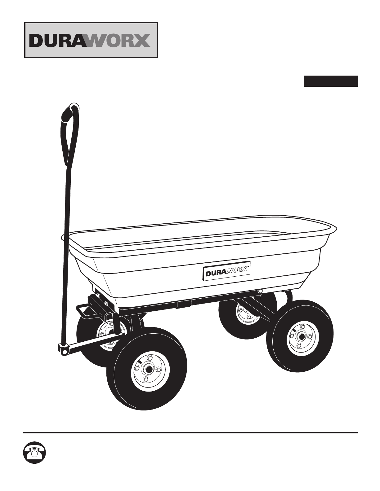
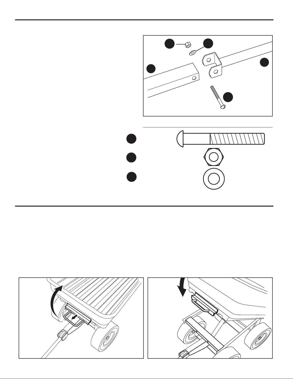
HARDWARE CONTENTS
Quantity
Picture
(Shown to size)
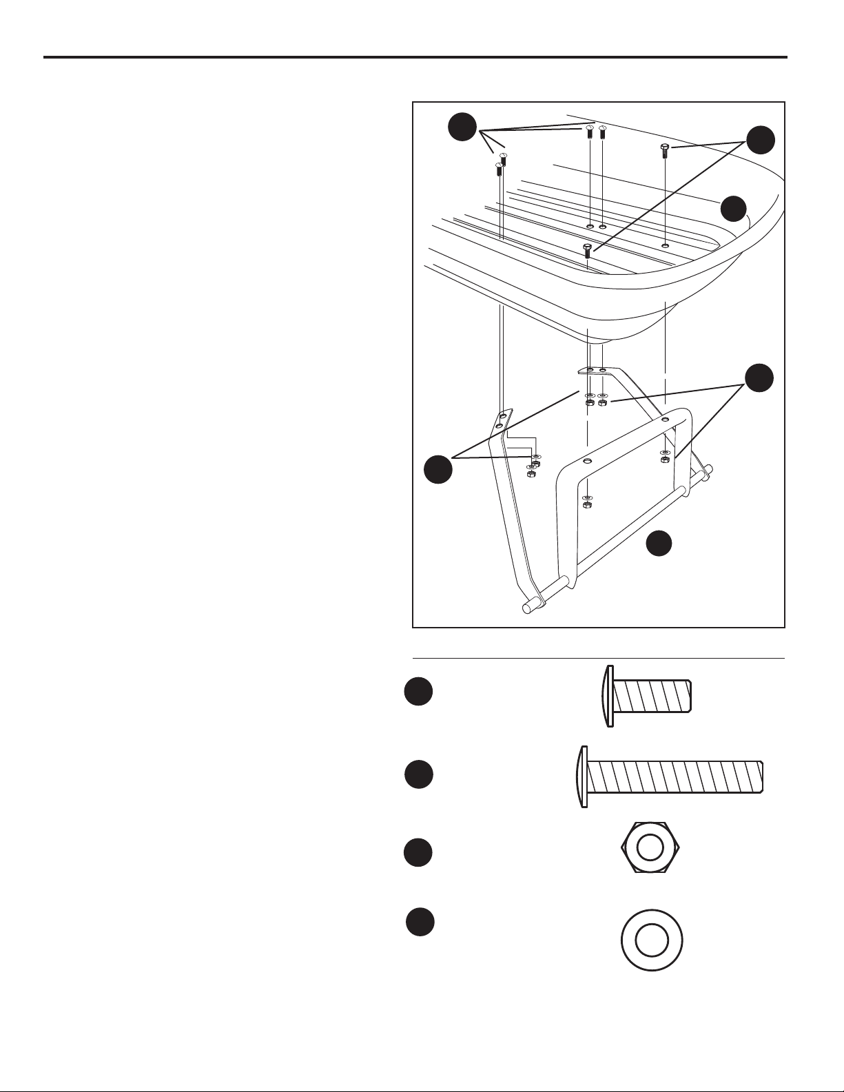
M8 x 60mm
Bolt
1
Part
M8 x 40mm
Truss
Head Bolt
24Wheel
Spacer
10
M8 x 20mm
Truss
Head Bolt
WARNINGS AND CAUTIONS
WARNING:
• Read, understand and follow ALL instructions before using this product.
• Do not exceed the overall maximum load capacity of 600 lbs. or the maximum dumping load
capacity of 300 lbs.
The weight rating is based on an evenly distributed load.
• Do not allow children to use the cart without supervision. This cart is not a toy.
• Do not use this cart for transporting passengers.
• This cart is not intended for highway use.
• Do not exceed 5 mph.
CAUTION:
• Distribute the load evenly over the surface of the tray.
• Do not load items on the top edges of the tray.
• If any parts become damaged, broken or misplaced, do not use the cart until replacement
parts have been obtained.
• Do not use the cart on surfaces or for transporting objects that can cause damage to the
pneumatic tires or tubes. Do not inflate the tires to more than 30 PSI (2.07 BAR).
• It is recommended that the cart be inspected for damage before each use.
• KEEP THESE INSTRUCTIONS FOR FURTHER REFERENCE.
PREPARATION
Before beginning assembly of product, make sure all parts are present. Compare parts with
package contents list and diagram above. If any part is missing or damaged, do not attempt to
assemble the product. Contact customer service for replacement parts.
Estimated Assembly Time: 30 minutes
Tools Required for Assembly: Flathead screwdriver, Phillips screwdriver and socket set
(or two adjustable wrenches).(tools not included)
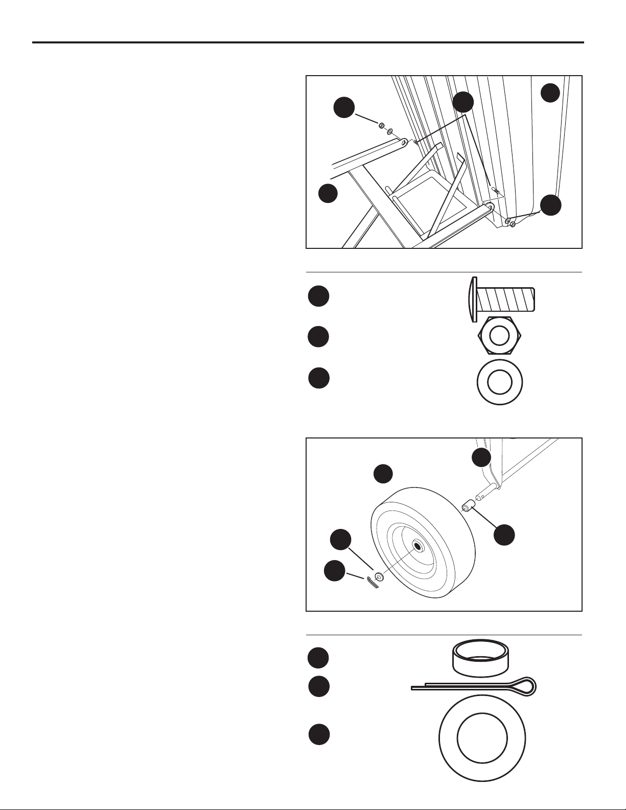
AA
DD
HH
4
5/8 in.
Washers
I I
4
Cotter Pin
JJ
CC
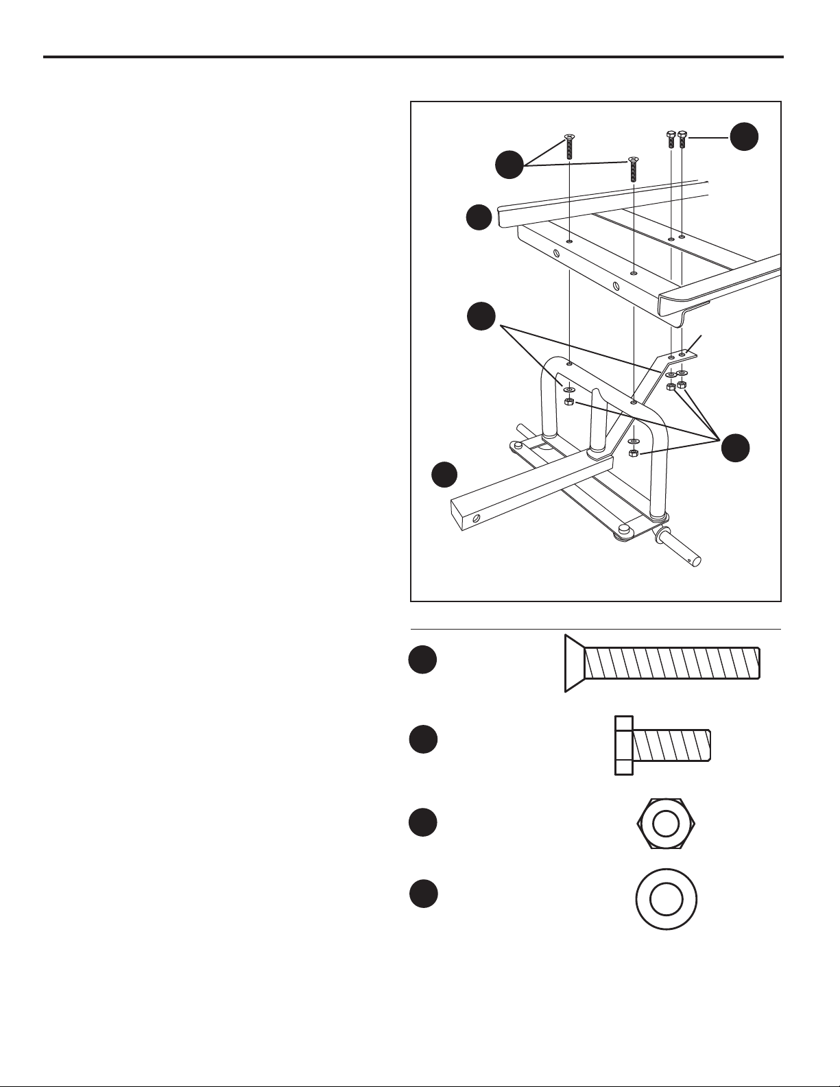
Description Quantity
Picture
(Shown to size)
M8
Lock Nut
17
Part
FF
Description
M8 x 40mm
Phillips Flat
Head Bolt
2
BB
M8
Washer 17
GG
2M8 x 20mm
Hex Head Bolt
EE
3