LFB Entel HT981 User manual

Policy
I
Procedure
IJIJm
LONDON
FIRE
BRIGADE
Entel HT981 intrinsically safe fireground radio
Official
New policy number:
593
Old instruction number: TEC:E015:a1 (b)
Issue
date:
12
July
2007
Reviewed
as
current:
28
July
2017
Owner: Head
of
Operational Policy
Responsible
work
team: Incident Communications
Contents
Entel
HT981
fireground radio ................
..
.................
..
.................
..
.
..
.......................................2
Key point summary
........................................................................................................
2
1 Introduction
.....................................................
.
..
.................
..
.
..
..............
..
....................2
2 Technical detail
for
the
ENTEL
HT981
radio ......
..
......
..
.........
..
......
..
.
..
......
..
.
..
......
..
...
..
.
..
.......3
3 Technical detail
of
battery
................................................................................................
3
4 Fitting/removal
of
battery
................................................................................................
4
5 Accessory connector .......................
..
..............
..
.
..
.................
..
.......................................4
6 Operatinginstructions..................
..
.
..
..............
..
..
..
.............
..
.
..
.................................
..
.....5
7 Charging
......................................................................................................................
6
8 Allocation and stowage
...................................................................................................
7
9 Repair
.............................................
.................
..
.
..
.................
..
..............
..
....................7
10 Testing, care and maintenance ......
.. ..
.........
..
.
..
.
.. ..
.........
..
....
.. ..
...............
..
.
.. ..
...
..
....
..
.
..
.....7
Appendix 1 -
Fire
ground channel
use
........................................................................................
8
Appendix
2-
ENTEL
HT981
radio operatingfunctions
..................................................................
9
Appendix
3-
ENTEL
HT981
intrinsically
safe
radio (in yellow
case)
with B.A.
R.I.
E.
connected ........... 10
Appendix
4-
ENTEL
CSB640E
6-
WAY
Rapid battery charger ....................
..
.
..
.................
..
........
11
Appendix
5-
Repairs/replacement procedure ......
.. ..
...............
..
.
.. ..
.........
..
....
.. ..
....
..
......
.. ..
....... 12
Document history
........................................................................................................
16
Review date:
28
July
2020
Last
amended date:
593
Issue
date: 12 July 2007 1
of
17
LFB00013099_0001
LFB00013099/1

Entel HT981 fireground radio
• The Entel HT981
is
an
intrinsically safe (IS) fireground radio.
•
Each
and every BA crew must have
at
least one means
of
radio communication. BA crews are
not
to
be committed
without
communications equipment.
• Dedicated BA Radio Interface Equipment (B.A.R.I.E.) provides
an
enhanced level
of
audibility
for
both
transmission and reception.
•
If
dedicated B.A.
R.I.
E.
sets are not available a minimum
of
a handheld radio must be carried.
Entel 480/1 personal issue handheld radios are
not
intrinsically safe (IS), and must not be
used in flammable
or
explosive atmospheres and should only be used where BARIE sets are
unavailable, and only after a risk assessment
has
been undertaken. (Please refer
to
Policy
Number
458-
Entel HX-480/1 hand held incident ground radio
for
further
information).
•
In
all
instances, initial BA crews deployed into compartments where a potentially explosive
atmosphere may be present must be wearingintrinsically safe B.A.
R.I.
E.
sets.
• Prior
to
rigging in
BA,
It
is
recommended that B.A.
R.I.
Ewearers
turn
the radio on and lock it
to
the appropriate channel.
Key point summary
• The Entel HT981
is
an
intrinsically safe fireground radio.
• The radio conforms
to
all
the current requirements
of
the European ATEX Directive.
Equipment and Protective Systems intended
for
use in Potentially Explosive Atmospheres
(ATEX).
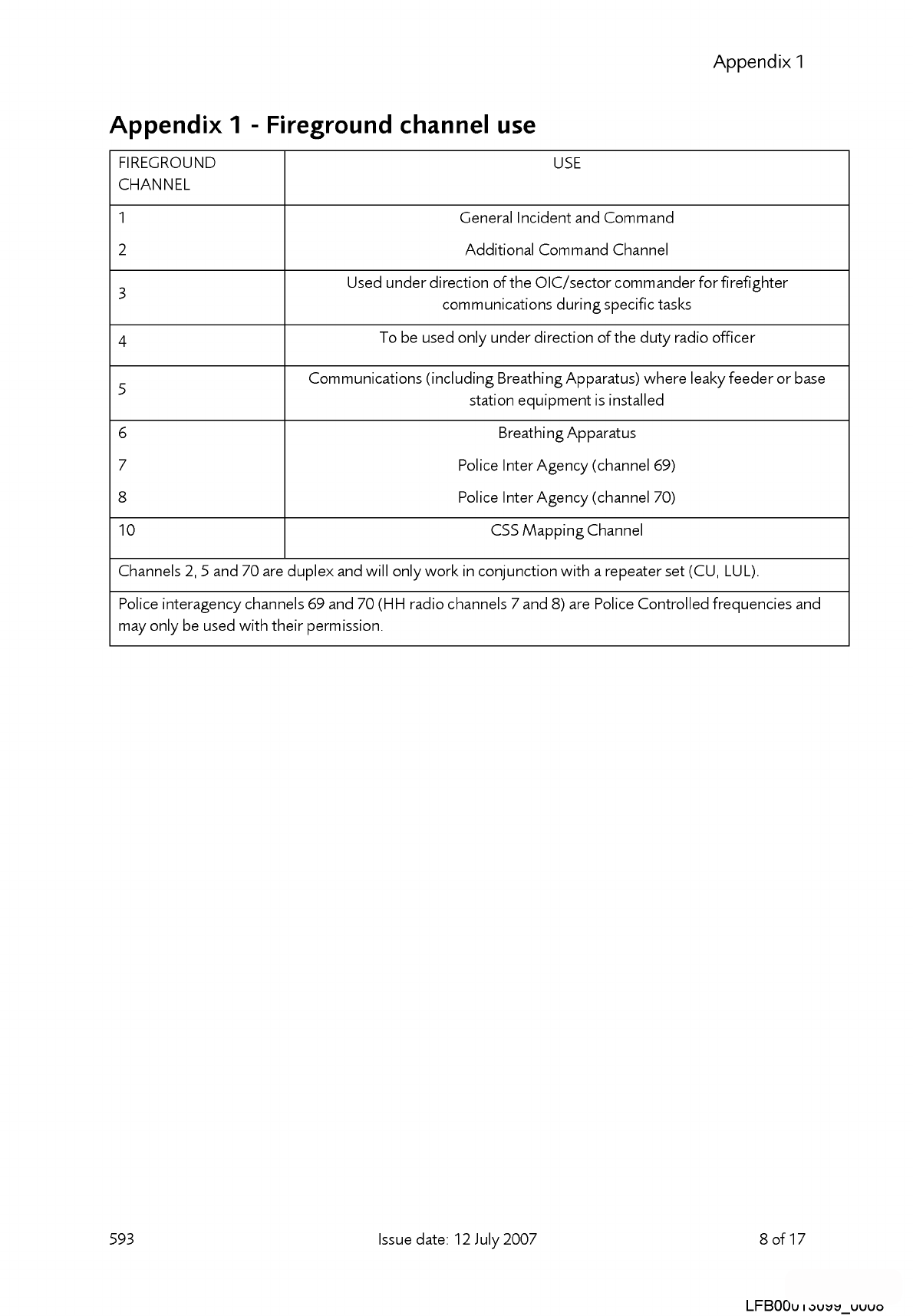
• The radio uses the same channels
as,
and
is
fully
interoperable with, existing incident ground
radios
(Appendix
1
).
•
In
normal use the radio
is
housed in a
yellow
protective
case.
• The radio
is
permanently connected
to
a B.A.
R.I.
E.
set
(Appendix
3).
•
Only
Radio
Workshop
personnel will disconnect B.A.
R.I.
E.
from the Entel HT981 radio.
Tampering
with
this connection could affect the level
of
intrinsic safety, and the B.A.
R.I.
E.
would
subsequently be classed
'off
the run' and defective.
•
Each
radio
has
a brigade serial
number
starting
LFB
001
and onwards and shall be recorded on
the station inventory.
-
Each
B.A.
R.I.
E.
component (Press
to
talk (PTT), Bone Conduction
Microphone/Ear
Speaker) have brigade serial numbers starting
LFB
001
and onwards. These will be
recorded on the station inventory.
-It
is
vitally important that B.A.
R.I.
E.
components and connected radio, remain
together
in
their
unit,
as
issued
by
Radio Workshops.
•
Each
battery
has
a serial
number
and shall be recorded on the station inventory.
• The testing and replacement
of
batteries
for
the
Entel radio differs from existing procedures.
• Radio batteries are
to
be maintained strictly in accordance
with
the procedures outlined in this
policy.
• This policy must be read
together
with
Policy
Number
516 -Entel HT981
Fire
ground Radio
and Savox interface Equipment B.A.
R.I.
E.
dated 12 July 2007.
Safety precaution
Never attempt
to
remove a battery in aflammable
or
explosive atmosphere.
1 Introduction
1.1 This policy provides information relating
to
the use and function
of
the
Entel HT980 series
incident ground radios.
593 Issue date: 12 July 2007 2
of17
LFB00013099_0002
LFB00013099/2

1.2
The
Entel HT981 radio
is
certified
to
an intrinsically
safe
standard
of
E
Ex
ib
IIC
T4
which
is
suitable
for
use
in
a flammable
or
explosive
atmosphere.
The
radio
will
be
permanently
connected
to
and
only
used
with Breathing
Apparatus
Radio Interface
Equipment
(B.A.
R.I.
E.)
as
recommended
by
the
Home
Office
in
DCOL6/1992.
Note:
Under
no
circumstances
are
station
personnel
to
attempt
to
remove
the
B.A.
R.I.
E.
from
the
radio
in
order
to
use
the
radio
for
general
fireground
communications
or
attach
a non
IS
radio
to
the
BA
set.
The
radio,
B.A.
R.I.
E
and
protective
case
are
to
be
treated
as a
complete
unit.
1. 3
The
Entel HT980
series
are
programmed
to
the
same
incident
ground
channels
already
in
use
by
the
LFB
(Appendix
1
).
1.4
Each radio
is
supplied
with
two
Lithium ion intrinsically
safe
batteries.
1.5
Each radio
will
be
provided
with a yellow
protective
case.
1.6
Each location within
the
Authority
issued
with Entel
HT-
981 radios
will
be
provided
with
an
appropriate
battery
charger.
2 Technical detail for the ENTEL HT981 radio
2.1
The
radio consists
of
a single unit
transceiver
with
an
internal
microphone,
loudspeaker
and
external aerial
and
has a transmit
power
output
of
1
Watt
ERP
(effective radiated power).
2.2
Dimensions
of
the
radio with a
battery
fitted are:
59mm
(W),
33mm
(D),
130mm
(H)
and
it
weighs
296g.
2.3
The
radio
is
fully
splash
proof
and
SUBMERSIBLE,
exceeding
all
aspects
of
the
European
ATEX
Directive.
(However
this
is
a quality
of
the
radio
in
its
manufacture
and
not
an
intended
use
when
connected
to
a
B.A.
R.I.
E.).
2.4
The
radio
uses
Angle
Modulation
(FM)
and
operates
on
25KHz
channel
spacing.
2.5
The
radio
is
fully
programmable
across
a
range
of
frequencies
with
up
to
128
channels,
although
for
LFB
use, only 9
channels
have
been
programmed.
2.6
Channels
1, 3, 4,
6,
10(CSS),
and
7 (Police
Interagency
69) receive
and
transmit
on
one
frequency.
2.
7
Channels
2,
5
and
8 (Police
Interagency
70) receive
and
transmit
on
different
frequencies.
These
channels
will
only
work
in
conjunction
with
repeater
sets
carried
on
Command
units
and
installed
in
LUL
premises)
(Appendix
1).
Note:
Channels
7
and
8
are
Police controlled
frequencies
and
are
only
to
be
used
with
their
perm1ss1on.
3 Technical detail
of
battery
3.1
7.4v
1800
mAh
rechargeable
Lithium ion
(Li
ion).
3. 2 A fully
charged
battery
will
have
a
working
duration
of
12-14
hours.
3. 3 A fully
discharged
battery
takes
approximately 6
hours
to
charge.
3.4
Under
no
circumstances
should
the
battery
terminals
be
short
circuited.
It
is
important
that
the
spare
battery
is
not
stored
together
with metal objects.
3.5
Due
to
the
construction
of
the
battery
(Li
Ion)
it
does
not
require
a
monthly
discharge
process.
593
Issue date:
12
July
2007
3
of17
LFB00013099_0003
LFB00013099/3

4 Fitting/removal
of
battery
4.1 Always
turn
the
radio off before installing
or
removing
the
battery.
4. 2 To fit
the
battery, first
ensure
that
the
battery
connections are clean
and
that
the
battery
is
in
good
condition. Offer
the
battery up
to
the
rear
of
the
radio
and
ensure
the
tabs
at
the
base
of
the
battery
are located
in
the
rear lowerface
of
the
radio. Press
the
battery
towards
the
rear
of
the
radio
engaging
the
battery locking
screw
(picture 1
).
Rotate
the
locking
screw
clockwise until
finger tight.
Do
not
over
tighten.
4. 3 To
remove
the
battery:
• Turn
the
radio off.
• Hold
the
radio
and
rotate
the
battery locking
screw
anti-clockwise. Ensure
you
do
not hold
the
battery pack
when
unscrewing
the
release
screw
as
the
radio may
fall
to
the
floor.
•
Then
lift
the
battery away from
the
body
of
the
radio.
Locking
Screw
Picture 1
5 Accessory connector
5.1
The
Entel HT981 radio
is
an integral part
of
the
B.A.
R.I.
E.
5. 2
The
radio
and
B.A.
R.I.
E.
are joined by an accessory
connector
(picture 2).
5.3
No
attempt
is
to
be
made
to
separate
these
components
except
by trained Radio
Workshops
Staff.
5.4
The
accessory
connector
is
secured
using a special fixing
method.
593
Accessory
Connector
Picture 2
Issue date:
12
July
2007
12
pin
B.A.
R.I.
E.
connection
4
of17
LFB00013099_0004
LFB00013099/4

6 Operating instructions
6.1 Please note
that
Appendix
2 indicates
the
position
of
each
switch
and
should
be
studied
before
use.
Radio
on/off
and
volume control
6.
2 To
turn
on
the
radio
press
the
power
switch,
the
radio
will
bleep
to
indicate a self
test
'London
Fire'
and
the
radio serial
number
will
appear
in
the
LCD
screen.
The
radio
will
then
default
to
the
last channel
selected
and
display this on
the
LCD
screen.
6.
3 Adjust
the
volume
to
a comfortable listening level by rotating
the
volume knob. Rotating
the
knob
clockwise
will
increase volume
and
anticlockwise
will
decrease
volume,
the
volume level
indicated
on
the
LCD
screen
in
a series
of
1
to
16
bars.
There
is
no limit
stop
on
the
rotating
switch.
6.4
To
turn
the
radio off,
press
and
hold
the
power
switch until
it
bleeps
and
the
words'
Powering
off'
appear
in
the
LCD
screen.
Channel selection switches
6.5
The
desired
channel
is
selected
using
the
up/down
arrows
on
the
front face
of
the
radio,
the
selected
channel
will
be
displayed
on
the
LCD
screen. Channel 6 must
be
selected
by
the
wearer
for
BA
Communications
or
ChannelS
if
base
station
and
leaky
feeder
equipment
are installed.
Battery level
6.
6
The
battery level
is
indicated by
the
icon (displayed above)
in
the
top
right
of
the
LCD
display. A
solid block indicates
the
battery
is
charged
and
ready
for use.
When
routine
checks
are
being
completed,
if
the
level indicated falls
to
2/3rds
full
the
battery
should
be
changed.
Key lock
6.
7
The
radio can
be
key locked
in
order
to
prevent
accidental
change
of
channel. The
appropriate
channel
is
key locked by
pressing
and
holding
the
TICK
button
for 3
seconds,
and
a padlock
symbol
will
appear
in
the
LCD
screen.
When
in
lock
mode
the
radio
cannot
be
accidentally
turned
off. To unlock
the
channel press
and
hold
the
TICK
button
for 3
seconds,
the
radio can
then
be
turned
off by pressing
the
power
key.
Key tone indicator
6.8
This indicates
that
the
key
tone
bleep
is
on; which
will
give a positive indication
of
changing
channels, key lock function,
turning
radio
on
and
off.
593
Issue date:
12
July
2007
5
of17
LFB00013099_0005
LFB00013099/5

High power indicator
6.
9 This indicates
the
power
of
the
channel
and
is
represented
by an
"H
".
All
channels
are
high
power.
Volume level control
6.10
This
is
indicated on a
graduated
bar
1
to
16
on
the
LCD
screen
when
the
volume
is
increased
or
decreased.
Ancillary switches and controls
6.11
The
radio has a
range
of
other
specific functions
which
are not
required
for fire service use.
The
controls for additional functions
have
been
disabled
on
the
radios.
The
operation
of
unused
function controls
buttons
will
cause
the
radio
to
beep
and
the
LCD
screen
to
illuminate,
but
will
not
otherwise
affect
the
performance
of
the
radio
(Appendix
2).
Transmission
6.12
Before transmitting, monitor
the
desired
channel
to
ensure
it
is
clear.
When
receiving a signal,
wait until
the
signal
stops
before
transmitting.
The
radio
cannot
transmit
and
receive
simultaneously. Pressing
the
transmit switch (PTT)
on
the
B.A.
R.I.
E.
begins
transmission,
to
confirm transmission
the
LED
on
top
of
the
radio
will
illuminate
RED.
6.13
When
the
radio
is
receiving a signal
the
LED
will
illuminate
green.
7 Charging
7.1 Each station
will
be
supplied
with station
chargers
(Appendix
4). Personnel
must
ensure
that
the
spare
batteries are fully
charged
at
all
times.
7.
2 A
battery
should
be
changed
when
the
charge
indicator
shows
2/3rds
charged.
7.3
Place
the
spare
battery
in
the
charger.
The
LED
light
will
be
red
and
will
go
green
when
the
charge
is
complete. A
battery
should
be
charged
after
prolonged
use
or
if
following routine
checks
the
battery level indicator
drops
low.
7.4
When
the
charger
is
connected
to
the
mains
supply
the
LED
indicators
will
flash momentarily
to
amber
indicating
correct
operation.
All
batteries
will
charge
independently
and
are not reliant on
any
one
battery
becoming
fully
charged
before
another
can
begin.
7.5
When
a
battery
is
inserted
the
LED
will
illuminate red
to
indicate
the
charging
process
has
begun.
7.6
Charging
time for a fully
discharged
battery
will
take
up
to
6 hours.
On
completion
the
LED
will
turn
green.
Note
that
the
green
LED
will
illuminate after approximately 3
hours
but
the
battery
should
be
left
to
charge
for a
further
3 hours.
7.
7 A faulty
battery
will
cause
the
LED
to
flash red.
7.8
Due
to
the
construction
of
the
battery
(Li
Ion)
it
does
not require a monthly
discharge
process.
593
Issue date:
12
July
2007
6
of17
LFB00013099_0006
LFB00013099/6

8 Allocation and stowage
8.1
The
Entel HT981
will
be
permanently
connected
to
a
set
of
BAR
IE
and
allocated
to
appliances as
follows:
• PL- 2 radios
each
with 1 battery
per
radio
•
P-
2 radios
each
with 1 battery
per
radio
•
FRU-
2 radios
each
with 1 battery
per
radio
8. 2 Each radio with
one
battery
attached
will
be
contained
within a yellow protective case.
The
cases
are
not
interchangeable
with any
other
equipment.
8. 3 An additional battery
per
radio
is
provided,
together
with a station multiple
charging
facility for
each
radio
(see
Appendix
4).
9 Repair
9.1
BARIE
that
fails
to
operate
for no
apparent
reason
is
to
be
immediately
taken
out
of
service and
sent
for repair on a POMS order.
9.2
IMPORTANT: Please
refertothe
repairflowcharts
in
appendix5
of
this policy.
9. 3 Stations
who
require an
urgent
replacement
BAR
IE
(refer
to
flowcharts
in
appendix
5)
of
defective 6
way
battery
charger
must
contact
the
logistics officer at
the
Resource
Management
Centre
(RMC) on extension 88321. A
replacement
BAR
IE
or
charger
will
then
be
delivered by an
Operational
Support
Unit (OSU).
There
is
no
current
requirement
for stations
to
generate
a
POMS
order
for
urgent
replacements, with
the
exception
of
the
OSU stations
who
will
need
to
replenish
the
OSU stock.
9.4
Defective batteries
and
radio
cases
will
be
replaced
by
Radio
Workshops.
Contact
the
workshop
on
extension 30561 detailing
the
fault.
9.5
Any
damaged
BARIE
equipment
(other
than
fair
wear
and
tear), must
be
returned
to
Radio
Workshops
detailing
the
fault,
and
accompanied
by a
memorandum
detailing
the
circumstances
in
which
the
damaged
occurred,
and
verified by
the
station manager.
9. 6
All
components
of
the
BAR
IE
must
be
kept
together
in
the
blue transportation
bag
whenever
they
are
returned
to
Radio
Workshops.
10
Testing. care and maintenance
10.1
All
fire
ground
radios are
tested
on
the
following occasions:
• on receipt
•
when
allocated
to
a
wearer
• after use
•
when
recalled by radio workshops.
10.2
Daily check:
turn
on
radio, listen for
the
momentary
bleep (this
is
a self
test
to
confirm working)
Note battery
strength
indicator, batteries
should
be
changed
when
battery level indicator
is
showing
2/3rds
full
strength. Carry
out
a range
test
to
check
the
receiver strength.
Ensure the radio
is
turned
off
when not
in
use.
10. 3 Weekly: Carry
out
a
1OOM
range
test
by
transmitting
and
checking
the
receiver strength.
If
no
signal
is
received this
will
indicate
if
the
radio
is
defective.
10.4
If
the
radio
becomes
dirty
it
may
be
cleaned
with a
damp
cloth. A mild
soap
solution can
be
used
to
clean
the
case.
593
Issue date:
12
July
2007
7
of17
LFB00013099_0007
LFB00013099/7

Appendix 1
Appendix 1 - Fireground channel
use
FIREGROUND
USE
CHANNEL
1 General Incident and Command
2 Additional Command Channel
3 Used underdirection
of
the OIC/sector
commanderforfirefighter
communications
during
specific tasks
4 To
be
used only under direction
of
the
duty
radio officer
5 Communications (including BreathingApparatus) where leaky feeder
or
base
station equipment
is
installed
6 BreathingApparatus
7 Police InterAgency (channel 69)
8 Police InterAgency (channel 70)
10
CSS
Mapping
Channel
Channels
2,
5 and 70
are
duplex and will only
work
in conjunction with a repeater set (CU, LUL).
Police interagency channels 69 and 70 (HH radio channels 7 and 8)
are
Police Controlled frequencies and
may only
be
used with their permission.
593 Issue date: 12 July 2007 8
of17
LFB00013099_0008
LFB00013099/8

Appendix 2
Appendix 2 - ENTEL HT981 radio operating functions
Aerial
MON
button
(disabled)
Press
to Talk
--------...,j~
(PTT)
Radio Lock
'TICK'
593
On/Off
Button
NB:
This
is
a
quality
of
the
radio
in
its
manufacture
and
not
an
intended
use
when
connected
to a
B.A.R.I.E
..
______
Volume Control
Issue
date: 12 July 2007
LED
for
Transmitting
(red) and Receiving
(green)
Channel
Up/Down
Please
note
that
theM
(Menu),
P1, P2,
Orange,
and
MON
buttonsare currently
disabled.
9
of17
LFB00013099_0009
LFB00013099/9

Appendix 3
Appendix 3 - ENTEL HT981 intrinsically safe radio (in
yellow case) with B.A.R.I.E. connected
Ear
Speaker
and
facemask
attachment
593
Bone Conduction
Microphone
and
facemask
attachment
Press To
Issue date:
12
July
2007
10
of
17
LFB00013099_0010
LFB00013099/10

Appendix4
Appendix
4-
ENTEL CSB640E
6-
WAY
Rapid battery
charger
Red
LED
indicating
battery
is
charging
593 Issue date: 12 July 2007
Green
LED
indicating battery
is
charged
Power Switch
11
of
17
LFB00013099_0011
LFB00013099/11

Appendix5
Appendix 5 -Repairs/replacement procedure
Breathing Apparatus Radio Interface
Equipment-
repairs/replacement
procedure (Stations)
The
following
diagram and
text
lays
out
the procedure
for
stations
to
report faulty
BARIE
sets and
arrange
for
replacement
or
repairs.
The minimum
number
of
BARIE
sets
is
1
per
pumping
appliance, and 2 per
FRU
(where applicable).
If
numbers
drop
below
this level then
RMC
are
to
be informed; RMC will order
an
Operational Support
Unit
to
provide a replacement
BARIE.
Defective set at station
Are
there sufficient BARIE sets
for
1
per
pumping appliance (and 2
per
FRU)?
Yes
Raise a POMs order stating the
nature
of
the defect, equipment
type
(e.g., Entel
or
Motorola
BARIE
set), and the serial number.
Faulty equipment
to
be sent via
van service
to
Radio Workshops,
Ruislip Fire Station.
Notes:
• Equipment must be sent
to
RWS
as
a
complete
set-
this
is
to
include
IS
radio
and case, microphone, and Press
to
Talk sw itch.
• Both collection and return
of
equipment
will be v
ia
the Brigade's v
an
service.
No
Contact RMC and report fault
as
an
urgent defect.
RMC will order the nearest OSU
to
replace
the
defective BARIE set.
Notes:
•
Equipment
must be sent
as
a complete
set-
this
is
to
include
IS
radio and case,
microphone, and Press
to
Talk switch.
• The station does
not
have
to
create a
POMS
order-
this
will
be carried
out
by
the OSU
driver
.
• The replacement BARIE set may
not
be
the
same
type
as
the
defective
equipment.
593 Issue date: 12 July 2007 12
of
17
LFB00013099_0012
LFB00013099/12

Appendix5
Breathing
Apparatus
Radio
Interface
Equipment-
repairs/replacement
procedure
(RMC)
The
following
diagram and
text
lays
out
the procedure
for
RMC
when
stations report afaulty
BARIE
set.
593
The minimum
number
of
BARIE sets per station
is:
1
perfront-line
pumping
appliance, and
2
per
FRU
(where applicable).
Defective
set
at
station
D
RMC
contacted
by
station
to
report
defect
D
RMC
confirm
that
there
are
insufficient
BARIE
sets
at
the
station
to
maintain
1
per
pumping
appliance
and
2
per
FRU
(if applicable)
Insufficient
(appliance
offthe
run)
Station
advised
that
an OSU will
be
sent
to
collect
the
defective
BARIE
set
and
replace
it
with
sufficient
numbers
to
put
the
vehicle
back
into
operational
service.
Station
reminded
that
they
are
not
to
raise a POMs
order
for
the
defective
equipment.
RMC
to
mobilise
the
nearest
OSU
with
a
replacement
BARIE
set.
RMC
remind OSU
driver
that
they
need
to
create
a POMs
order
for
the
defective
BARIE
set
on
their
return
to
base.
Issue date: 12 July 2007
Sufficient
(appliance
stays
on
the
run)
~
Station
advised
that
they
should
raise
a POMs
order
stating
the
nature
of
the
defect,
equipment
type
(e.g.,
Entel
or
Motorola
BARIE
set),
and
the
serial
number.
Remind
station
that
faulty
equipment
to
be
sent
via Brigade's
day
van
service
to
Radio
Workshops,
Ruislip
Fire
Station.
Note:
Both collection and return
of
equipment will
be
via the Brigade's van service.
13
of
17
LFB00013099_0013
LFB00013099/13

Appendix5
BreathingApparatus Radio Interface
Equipment-
repairs/replacement procedure (Operational Support
Vehicles)
The
following
diagram and
text
lays
out
the procedure
for
OSU drivers
when
replacingfaulty BAR
IE
sets
at stations.
The minimum
number
of
BARIE
sets
is
1
per
pumping
appliance, and 2 per
FRU.
If
numbers
drop
below
this level
then
RMC are
to
be informed, and
they
will
order
an
OSU
to
provide 1 BAR
IE
set
as
a
replacement.
593
Defective set
at
station
OSU contacted by RMC
with
details
of
faulty
BARIE set
at
station.
D
OSU
driver
confirm
that
they
have sufficient stock
to
carry out a replacement.
D
Visit station and collect defective BARIE set.
Make
note
of
nature
of
fault
and
set number.
Issue replacement BARIE set
to
station.
Make
note
of
set
number
issued
On return
to
base, raise a POMs
order
for
defective equipment stating
the
nature
of
the
defect, equipment
type
(e.g., Entel or
Motorola
BARIE set), serial
number, and
the
originating station.
Email"lncident
Comms"
with
the
replacement set
number
and station
allocated.
Faulty equipment should then be sent via van service
to
Radio Workshops,
Ruislip Fire Station.
Notes:
• Equipment must be sent
to
RWS
as
a complete
set-
this includes radio and case,
microphone, and Press
to
Talk switch.
• Both collection and return
of
equipment
will be via the Brigade's van service.
•
OS
Us are
only
to
provide stations
with
sufficient
equipment
to ensure
that
minimum levels
of
BARIE sets are maintained.
Issue date: 12 July 2007 14
of
17
LFB00013099_0014
LFB00013099/14

Appendix5
Breathing Apparatus Radio Interface
Equipment-
repairs/replacement
procedure (Radio Workshops)
The
following
diagram and
text
lays
out
the procedure
for
Radio
Workshops
when
stations report a
faulty BAR
IE
set.
593
The minimum
number
of
BARIE sets per station
is:
1
perfront-line
pumping
appliance, and
2
per
FRU
(where applicable).
Defective set
at
station
D
RWS receive POMs order.
Note
whether
order
from
OSU station or
other
location.
FROM
osu
station
NOT
from
osu
station
RWS dispatch
new
BARIE set
to
OSU
station. Note replacement set
number
and location.
RWS dispatch replacement set
to
station.
Note
details
of
exchange and
email
to
Incident Comms.
RWS take details
of
defective set and
original set location.
Email details
of
the
exchange
to
Incident Comms. Include serial
number
of
defective BARIE,
replacement BARIE and its intended
location.
Note:
Both collection and return
of
equipment
will
be via
the
Brigade's van service.
Issue date: 12 July 2007
Note:
Both collection and return
of
equipment
will
be via the Brigade's van service.
15
of
17
LFB00013099_0015
LFB00013099/15

Document history
Assessments
An equality, sustainability
or
health,
safety
and
welfare impact
assessment
and/or
a risk
assessment
was
last
completed
on:
I
EIA
111/09/2008 I SDIA I 20/11/2013 I HSWIA
Audit trail
Listed
below
is
a briefaudit trail, detailing
amendments
made
to
this
policy/procedure.
Page/para
nos. Brief
description
of
change
Date
Page
7 Section
Changes
made
to
Section
9-
paragraphs
9.1
to
9.4 23/08/2008
9
Throughout
Policy
reviewed
as
current,
minor
wording
changes
made
01/09/2011
throughout
and
arrows
repositioned
in
appendices
to
correctly
indicate
the
parts
of
the
images.
Throughout
This policy
has
been
protectively marked. 24/01/2012
Page
16
SIA
date
added.
26/11/2013
Page
1
The
'Protect'
mark
on
this policy has
been
changed
to
'Official'
to
20/03/2014
bring
us
in
line with
the
Government
classification
scheme.
Throughout
Reviewed as
current,
no
changes
made.
17/07/2014
Page
16
'Subjects
list'
table-
template
updated.
02/02/2015
Throughout
This policy
has
been
reviewed
as
current
with
no
changes
made
to
28/07/2017
the
content
at this time.
Subject list
You
can
find this policy
under
the
following subjects.
IS
radio Radio
-IS
Incident
Management
Incident
Command
Assets
Equipment
BAComms
BA
radio
BARIE
Communication
and
messages
Entel radio Incident
Communications
Intrinsically safe Radios
593
Issue date:
12
July
2007
16
of
17
LFB00013099_0016
LFB00013099/16

Freedom
of
Information
Act
exemptions
This
policy/procedure
has
been
securely
marked
due
to:
Considered
by:
FOIA exemption Security marking
(responsible
work
team)
classification
Jim
A'Court-
Incident
Selected
information
to
be
redacted.
Official
Communications
593 Issue date:
12
July
2007
17
of
17
LFB00013099_0017
LFB00013099/17
Table of contents