LG MFL40910613 User manual

ENGLISH FRANÇAIS ESPAÑOL
LG
Air Conditioner
INSTALLATION MANUAL
LG
website http://www.lgservice.com
IMPORTANT
• Please read this installation manual completely before
installing the product.
• Installation work must be performed in accordance with
the national wiring standards by authorized personnel
only.
• Please retain this installation manual for future reference
after reading it thoroughly.

2Air Conditioner
IMPORTANT!
CAUTION
: Improper installation, adjustment, alteration, service or maintenance can void the warranty.
The weight of the condensing unit requires caution and proper handling procedures when lifting
or moving to avoid personal injury. Use care to avoid contact with sharp or pointed edges.
Safety Precautions
• Always wear safety eye wear and work gloves when installing equipment.
• Never assume electrical power is disconnected. Check with meter and equipment.
• Keep hands out of fan areas when power is connected to equipment.
• R-410A causes frostbite burns.
• R-410A is toxic when burned.
NOTE TO INSTALLING DEALER: The Owners Instructions and Warranty are to be given to the owner
or prominently displayed near the indoor Furnace/Air Handler Unit.
When wiring:
Electrical shock can cause severe personal injury or death. Only a qualified,
experienced electrician should attempt to wire this system.
• Do not supply power to the unit until all wiring and tubing are completed or reconnected and checked.
• Highly dangerous electrical voltages are used in this system. Carefully refer to the wiring diagram and these
instructions when wiring. Improper connections and inadequate grounding can cause accidental injury or death.
• Ground the unit following local electrical codes.
• Connect all wiring tightly. Loose wiring may cause overheating at connection points and a possible fire hazard.
When transporting:
Be careful when picking up and moving the indoor and outdoor units. Get a partner to help, and
bend your knees when lifting to reduce strain on your back. Sharp edges or thin aluminum fins on
the air conditioner can cut your finger.
When installing...
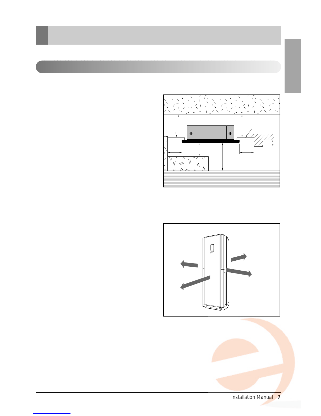
... in a wall: Make sure the wall is strong enough to hold the unit's weight.
It may be necessary to construct a strong wood or metal frame to provide added support.
... in a room: Properly insulate any tubing run inside a room to prevent "sweating" that can cause
dripping and water damage to wall and floors.
... in moist or uneven locatinons: Use a raised concrete pad or concrete blocks provide a solid,
level foundation for the outdoor unit. This prevents water damage and abnormal vibration.
... in an area with high winds: Securely anchor the outdoor unit down with bolts and a metal
frame. Provide a suitable air baffle.
... in a snowy area(for Heat Pump Model): Install the outdoor unit on a raised platform that is
higher than drifting snow. Provide snow vents.
When connecting refrigerant tubing
• Keep all tubing runs as short as possible.
• Use the flare method for connecting tubing.
• Check carefully for leaks before starting the test run.
When servicing
• Turn the power OFF at the main power box(mains) before opening the unit to check or repair
electrical parts and wiring.
• Keep your fingers and clothing away from any moving parts.
• Clean up the site after you finish, remembering to check that no metal scraps or bits of wiring have
been left inside the unit being serviced.
Special warnings
WARNING
• Installation or repairs made by unqualified persons can result in hazards to you and others.
Installation MUST conform with local building codes or, in the absence of local codes, with the National Electrical
Code NFPA 70/ANSI C1-1993 or current edition and Canadian Electrical Code Part1 CSA C.22.1.
• The information contained in the manual is intended for use by a qualified service technician familiar with safety
procedures and equipped with the proper tools and test instruments.
• Failure to carefully read and follow all instructions in this manual can result in equipment malfunction, property
damage, personal injury and/or death.
Please read this instruction sheet completely before installing the product.
This air conditioning system meets strict safety and operating standards. As the installer or service person,
it is an important part of your job to install or service the system so it operates safely and efficiently.

Installation Manual 3
ENGLISH
Air Conditioner Installation Manual
CONTENTS
Safety Precautions ..............................................................................................4
Installation of Indoor, Outdoor unit ...................................................................7
The indoor unit installation ..............................................................................10
Remote controller installation..........................................................................13
Wiring connection .............................................................................................16
Flaring Work and Connection of Piping ..........................................................20
Installation to decorative panel........................................................................23
Indoor unit drain piping ....................................................................................25
Test running .......................................................................................................29
Leakage test and Evacuation ...........................................................................32
Installation guide at seaside ............................................................................33

4Air Conditioner
Safety Precautions
To prevent the injury of the user or other people and property damage, the following instructions
must be followed.
■Be sure to read before installing the air conditioner.
■Be sure to observe the cautions specified here as they include important items related to safety.
■Incorrect operation due to ignoring instruction will cause harm or damage.The seriousness is
classified by the following indications.
■The meanings of the symbols used in this manual are as shown below.
This symbol indicates the possibility of death or serious injury.
This symbol indicates the possibility of injury or damage to properties only.
■Installation
Be sure not to do.
Be sure to follow the instruction.
Safety Precautions
Always perform grounding.
• Otherwise, it may cause
electrical shock.
Don’t use a power cord, a
plug or a loose socket which
is damaged.
• Otherwise, it may cause a fire
or electrical shock.
For installation of the product,
always contact the service
center or a professional
installation agency.
• Otherwise, it may cause a fire,
electrical shock, explosion or
injury.
Securely attach the electrical
part cover to the indoor unit
and the service panel to the
outdoor unit.
• If the electrical part cover of the
indoor unit and the service
panel of the outdoor unit are not
attached securely, it could result
in a fire or electric shock due to
dust, water, etc.
Always install an air leakage
breaker and a dedicated
switching board.
• No installation may cause a fire
and electrical shock.
Do not keep or use flammable
gases or combustibles near
the air conditioner.
• Otherwise, it may cause a fire
or the failure of product.
Ensure that an installation frame of the
outdoor unit is not damaged due to use for a
long time.
• It may cause injury or an accident.
Do not disassemble or repair the product
randomly.
• It will cause a fire or electrical shock.

Safety Precautions
Installation Manual 5
ENGLISH
Do not install the product at a place that there
is concern of falling down.
• Otherwise, it may result in personal injury.
Use caution when unpacking and installing.
• Sharp edges may cause injury.
Take the power plug out if
necessary, holding the head
of the plug and do not touch
it with wet hands.
• Otherwise, it may cause a fire
or electrical shock.
Do not use the power cord
near the heating tools.
• Otherwise, it may cause a fire
and electrical shock.
Do not open the suction
inlet of the indoor/outdoor
unit during operation.
• Otherwise, it may electrical
shock and failure.
Do not allow water to run
into electrical parts.
• Otherwise, it may cause the
failure of machine or electrical
shock.
Hold the plug by the head
when taking it out.
• It may cause electric shock
and damage.
Never touch the metal parts
of the unit when removing
the filter.
• They are sharp and may
cause injury.
Do not share the outlet with
other appliances.
• It will cause an electric shock
or a fire due to heat
generation.
Do not use the damaged
power cord.
• Otherwise, it may cause a fire
or electrical shock.
Do not modify or extend the
power cord randomly.
• Otherwise, it may cause a fire
or electrical shock.
Take care so that the power
cord may not be pulled
during operation.
• Otherwise, it may cause a fire
or electrical shock.
Unplug the unit if strange
sounds, smell, or smoke
comes from it.
• Otherwise, it may cause
electrical shock or a fire.
Keep the flames away.
• Otherwise, it may cause a fire.
Do not step on the indoor/outdoor unit and
do not put anything on it.
• It may cause an injury through dropping of the
unit or falling down.
Do not place a heavy object on the power
cord.
• Otherwise, it may cause a fire or electrical
shock.
When the product is submerged into water,
always contact the service center.
• Otherwise, it may cause a fire or electrical
shock.
Take care so that children may not step on
the outdoor unit.
• Otherwise, children may be seriously injured
due to falling down.
■Operation

6Air Conditioner
Safety Precautions
■Installation
Install the drain hose to ensure that drain
can be securely done.
• Otherwise, it may cause water leakage.
Install the product so that the noise or hot
wind from the outdoor unit may not cause
any damage to the neighbors.
• Otherwise, it may cause dispute with the
neighbors.
Always inspect gas leakage after the
installation and repair of product.
• Otherwise, it may cause the failure of product.
Keep level parallel in installing the product.
• Otherwise, it may cause vibration or water
leakage.
Avoid excessive cooling and perform
ventilation sometimes.
• Otherwise, it may do harm to your health.
Use a soft cloth to clean. Do not use wax,
thinner, or a strong detergent.
• The appearance of the air conditioner may
deteriorate, change color, or develop surface
flaws.
Do not use an appliance for special purposes
such as preserving animals vegetables,
precision machine, or art articles.
• Otherwise, it may damage your properties.
Do not place obstacles around the flow inlet
or outlet.
• Otherwise, it may cause the failure of appliance
or an accident.
■Operation

Installation of Indoor, Outdoor Unit
Installation Manual 7
ENGLISH
Installation of Indoor, Outdoor Unit
1. Indoor unit
Cassette type
• There should not be any heat source or steam
near the unit.
• There should not be any obstacles to prevent
the air circulation.
• A place where air circulation in the room will
be good.
• A place where drainage can be easily
obtained.
• A place where noise prevention is taken into
consideration.
• Do not install the unit near the door way.
• Ensure the spaces indicated by arrows from
the wall, ceiling, or other obstacles.
• The indoor unit must keep the maintenance
space.
Floor Standing type
• There should not be any heat source or steam
near the unit.
• There should not be any obstacles to prevent
the air circulation.
• A place where air circulation in the room will
be good.
• A place where drainage can be easily
obtained.
• A place where noise prevention is taken into
consideration.
• Do not install the unit near the door way.
• Ensure the spaces indicated by arrows from
the wall, ceiling, or other obstacles.
• The indoor unit must keep the maintenance
space.
Selection of the best location
Ceiling
Ceiling Board Ceiling Board
Floor
Unit:mm(inch)
Unit:mm(inch)
300(11-
13
/
16
)
or more
Above 2500(98-
7
/
16
)
4000(157-
1
/
2
) or less
1000(39-
3
/
8
)
or more
500(19-
11
/
16
)
or more 500(19-
11
/
16
)
or more
300(11-
13
/
16
) or less
400(16)
400(16)
50(2)
1000(39.4)

8Air Conditioner
Installation of Indoor, Outdoor Unit
2. Outdoor unit
1. If an awning is built over the unit to prevent
direct sunlight or rain exposure, make sure
that heat radiation from the condenser is not
restricted.
2. Ensure that the spaces indicated by arrows
around front, back and side of the unit.
3. Do not place animals and plants in the path
of the warm air.
4.Take the air conditioner weight into account
and select a place where noise and vibration
are minimum.
5. Select a place so that the warm air and noise
from the air conditioner do not disturb
neighbors.
more than 700
(27 9/16)
more than 300
(11 7/16) more than 300
(11 7/16)
more than 600
(23 21/32)
more than 600
(23 21/32)
Unit:mm(inch)

Installation of Indoor, Outdoor Unit
Installation Manual 9
ENGLISH
3. Piping length and the elevation
24k Btu/h
15.88(5/8) 9.5(3/8)
7.5(25) 5(16) 35(0.38)
Gas Liquid Standard Max. Standard Max
.
Capacity Pipe Size Length A Elevation B
*Additional
Unit : mm(inch) Unit : m(ft) Unit : m(ft)
refrigerant
Unit : g/m(oz/ft)
Outdoor unit
Indoor unit
A
B
Outdoor unit
Indoor unit
A
B
A
Oil trap
Outdoor unit
Indoor unit
B
CAUTION:
•Rated performance for refrigerant line length of:7.5m(25ft)
•Capacity is based on standard length and maximum allowance length is on the
basis of reliability.
•Improper refrigerant charge may result in abnormal cycle.
•Oil trap should be installed every 10 meters(32.8 ft).
50(164)
cassette type
30(98)
Floor standing type
30(98)
cassette type
20(66)
Floor standing type

10 Air Conditioner
The indoor unit installation
1. Cassette type
Level gauge
Ceiling
Ceiling board
TM/TN/TP Chassis
Unit:mm(inch)
875(34-7/16) (Ceiling opening)
787(30-15/16)
(Hanging bolt)
bolt)
684(26-15/16)(Hanging bolt)
671(26-7/16)
875(34-7/16) (Ceiling opening)
840(33-1/16)
Unit size
840(33-1/16)
Unit size
• Avoid the following installation location.
1. Such places as restaurants and kitchen where considerable amount of oil steam and flour is generated.
These may cause heat exchange efficiency reduction, or water drops, drain pump mal-function.
In these cases, take the following actions;
• Make sure that ventilation fan is enough to cover all noxious gases from this place.
• Ensure enough distance from the cooking room to install the air conditioner in such a place where it
may not suck oily steam.
2. Avoid installng air conditioner
in such places where
cooking oil or iron powder is
generated.
3. Avoid places where
inflammable gas is generated.
4. Avoid place where noxious gas is
generated.
5. Avoid places near high frequency
generators.
NOTICE
CAUTION :
•This air-conditioner uses a drain
pump.
•Install the unit horizontally using
a level gauge.
•
During the installation, care should be
taken not to damage electric wires.
• Select and mark the position for fixing bolts and piping
hole.
• Decide the position for fixing bolts slightly tilted to the
drain direction after considering the direction of drain
hose.
• Drill the hole for anchor bolt on the wall.
Use the ventilation fan
for smoke-collecting
hood with sufficient
capacity.
Cooking table
Air conditioner
Take enough
distance

The indoor unit installation
Installation Manual 11
ENGLISH
Set screw of
paper model (4 pieces)
Paper model
for installation
Ceiling board
150mm
(5-7/8 inch)
Ceiling board
Ceiling
Flat washer for M10
(accessory)
Keep the length of the bolt
from the bracket to 40mm(1-1/2 inch)
Open the ceiling board
along the outer edge of the
paper model
Flat washer for M10
(accessory)
Hanging bolt
(W3/8 or M10)
Nut
(W3/8 or M10)
Nut
(W3/8 or M10)
Spring washer
(M10)
Air Conditioner body
Keep the length of 15~18mm(5/8~3/4 inch)
between the air conditioner bottom surface
and the ceiling surface
• The following parts is option.
Hanging Bolt - W 3/8 or M10
Nut - W 3/8 or M10
Spring Washer - M10
Plate Washer - M10
CAUTION :Tighten the nut
and bolt to prevent unit from
falling off.
• Drill the piping hole on the wall slightly tilted to the
outdoor side using a Ø 70 hole-core drill.

12 Air Conditioner
The indoor unit installation
2. Floor Standing type
Wall
Core Drill
Tilt
Cut if necessary
More than
15mm(0.6 inch)
Wall
Plastic tube
(Bushing)
INSIDE OUTSIDE
200(7.9)
70 (2.8) 70 (2.8)
200(7.9)
Unit : mm (inch)
1.The mounting floor should be strong and solid
enough to prevent it from vibration.
2. Drill the piping hole with 70mm diameter hole-
core drill at either the right or the left of indoor
unit. The hole should be sightly slant to the
outdoor side.
3. Insert the plastic tube through the hole.
4. Cut the extruded outside part of the plastic
tube, if necessary.

Remote controller installation
Installation Manual 13
ENGLISH
Operationunit
ZONE
1234
Humidify
JET
AUTO
AUTOSWING OPERATION
FANSPEED
Programset
SUBFUNCTION
SETTEMP
RoomTemp
HI
MED
LO
Heater
Defrost
Filter
Preheat
Outdoor
Time
Timer
On
Setno. Time
Off 01 03 05 07 09 11 13 15 17 19 21 23
Operationunit
ZONE
1234
Humidify
JET
AUTO
AUTOSWINGOPERATION
FANSPEED
Programset
SUBFUNCTION
SETTEMP
RoomTemp
HI
MED
LO
Heater
Defrost
Filter
Preheat
Outdoor
Time
Timer
On
Setno.Time
Off 010305 07 09 11 1315 171921 23
5feet
(1.5meters)
Direct
Sun ray contact area
no
no
no
yes
Operationunit
ZONE
1234
Humidify
JET
AUTO
AUTOSWING OPERATION
FANSPEED
Programset
SUBFUNCTION
SETTEMP
RoomTemp
HI
MED
LO
Heater
Defrost
Filter
Preheat
Outdoor
Time
Timer
On
Setno. Time
Off 01 03 05 07 09 11 13 15 17 19 21 23
• Since the room temperature sensor is in the remote controller, the remote controller box should be
installed in a place away from direct sunlight, high humidity and direct supply of cold air to maintain
proper space temperature. Install the remote controller about 5ft(1.5m) above the floor in an area with
good air circulation at an average temperature.
Do not install the remote controller where it can be affected by:
- Drafts, or dead spots behind doors and in corners.
- Hot or cold air from ducts.
- Radiant heat from sun or appliances.
- Concealed pipes and chimneys.
- Uncontrolled areas such as an outside wall behind the remote controller.
- This remote controller is equipped with a seven segment LED. display. For proper display of the remote
controller LED's, the remote controller should be installed properly as shown in Fig.1.
Wired remote controller installation
Remote controller installation
(Fig.1)

14 Air Conditioner
Remote controller installation
1. Connect the wired remote controller cable
to the wired remote controller installation
board as shown in the right picture.
2. After fixing the cable to the guide slot,
attach the wired remote controller
installation board at the desired location.
• Before fixing the wired remote controller cable
to the guide slot, remove any clogged part of
the case in the direction to install before the
installation.
3. After locating the wired remote
controller installation board at the
desired location, screw the unit firmly.
(When there is a buried box, install the
wired remote controller board to fit the
buried box.)
• Use the screw provided.
4. After fixing the top part of the wired
remote controller to the installation
board as shown in beside picture, press
the bottom part to assemble the
controller to it’s board.
When disassemble the wired remote controller
from the installation board, use the driver as
shown in the right picture and insert it into the
hole with the arrow. And when you pull the driver
in the front direction, the wired remote controller
will be separated.
12V Red wire
SIG Yellow wire
GND Black wire
❊The wired remote controller cable is connected as factory default.
12V SIG GND
Red
Yellow
Black
Remote Controller
Cable
Guide slot
Fixate the remote
controller cable
to the guide slot.
Use the screws
for fixate the unit
firmly on the wall.
Installation board
<Front side of
installation board> <Rear side of
installation board>
Top
Bottom
Wall
Side
Wall
Side Wall
Side
Wall
Side Wall
Side
Installation of Wired remote controller(Cassette type)

Installation Manual 15
ENGLISH
Remote controller installation
5. Use the connecting cable to connect the indoor unit and the wired remote
controller.
6.When the distance between the wired remote controller and the indoor unit is
10m and above, use the extension cable.
When installing the wired remote controller, do not bury it in the wall.
(It can cause damage in the temperature sensor.)
Do not install the cable to be 50m or above.
(It can cause communication error.)
• When installing the extension cable, check the connecting direction of the connector of the remote
controller side and the product side for correct installation.
• If you install the extension cable in the opposite direction, the connector will not be connected.
• Specification of extension cable: 2547 1007 22# 2 core 3 shield 5 or above.
Check whether the connector
is connected correctly.
Connecting cable
Indoor
unit side
HOWTO MOUNT ONTO A WALL
HOW TO INSERT BATTERIES
1. Remove the battery cover from the remote
controller.
• Slide the cover according to the
arrow direction.
2. Insert the two batteries.
• Be sure that the (+) and (-) directions are
correct.
• Be sure that both batteries are new.
3. Re-attach the cover.
• Slide it back into position.
• Do not use rechargeable
batteries, such batteries differ
from standard dry cells in
shape, dimensions, and
performance.
• Romove the batteries from the
remote controller if the air
conditioner is not going to be
used for some long time.
Wireless remote controller installation

16 Air Conditioner
Wiring Connection
Power Input
Terminals on the outdoor unit
1(L1) 2(L2)
3
2(L2)1(L1)
Terminal Block Indoor
1(L1) 2(L2) 3 4 5
Connected to outdoor unit TO AIR
FRESH
KIT
OPTION
Wiring Connection
WARNING : Loose wiring may cause the terminal to overheat or result
in unit malfunction.
A fire hazzard may also exist.
Therefore, be sure all wiring is tightly connected.
RECOMMENDATION:
The power cord connected to the outdoor unit should be
comply with the following specifications: ETL recognized and CSA certified.
GN/YL
Line voltage
(208/230V)
AWG12
GN/YL
AWG18
RECOMMENDATION:
When using the separate wires as the power cord, please
secure the separate wires into the control box panel using tie wraps to hold all
wires together in place.
The power connecting cable connected to the indoor
and outdoor unit should be comply with the
following specifications: ETL recognized and CSA
certified.

Wiring Connection
Installation Manual 17
ENGLISH
To Outdoor Unit
A
3
2(L2)1(L1)
Procedure for Connecting the Cable to Indoor Unit, is as follows:
1. Open The Front Door Manually, as shown in Fig. 1.
2. Open the Control Box Cover (A) with Driver, ( ) as shown in Fig. 2.
3. Connect the Cables (LG doesn't supply) to the terminal Block of Indoor Unit, as shown in
Fig. 3.
4. Install a power supply line or connecting cables as the Fig. 4 in order to prevent the
connecting wires from being cut by sharp edge of the hole.
5. Secure the Control Box Cover (A) to its original position with the help of Driver( ).
6. Close the Front Door.
(Fig.1)
Detail Wiring for Indoor Unit
(Fig.3)
(Fig.2)
2. Floor Standing type
1. Cassette type
•Open the control box cover and connect the Remote controller cord and Indoor power wires.
Control box cover
Indoor
power cord
Remote
controller
cord Control box cover screw
Lock nut
Conduit
mounting
plate
Conduit
Connecting the Cable to Indoor Unit

18 Air Conditioner
Wiring Connection
Lock nut
(field supply)
Conduit
(field supply)
Conduit panel
Power supply line or
Connecting cable
Cap(Remove)
(Fig.4)

Installation Manual 19
ENGLISH
Electrical Wiring
Connecting the cable to Outdoor Unit
Wiring Connection
1. All wiring must comply with LOCAL REGULATIONS.
2. Select a power source that is capable of supplying the current required by the air conditioner.
3. Feed the power source to the unit via a distribution switch board designed for this purpose.
4.The terminal screws inside the control box may be loose due to vibration during transport.
Check the screws for loose connection.
(Running the air conditioner with loose connection can overload and damage electrical
components.)
5. Always ground the air conditioner with a grounding wire and connector to meet the LOCAL
REGULATION.
1. Remove the Cover control from the unit by
loosening a screw.
Connect the wires to the terminals on the
control board individually as following.
2. Secure the cable onto the control board with
the holder (clamper).
3. Refix the cover control to the original position
with the screw.
4. Use a recongnized circuit breaker between
the power source and the unit. A
disconnection device to adequately
disconnect all supply lines must be fitted.
CAUTION:
•The circuit diagram is not subject to
change without notice.
•Be sure to connect wires according
to the wiring diagram.
•Connect the wires firmly, so that not
to be pulled out easily.
•Connect the wires according to
color codes by referring the wiring
diagram.
Air
Conditioner
Main power source
Circuit Breaker
Use a 25A circuit breaker
or time delay fuse.
Outdoor unit
Over 5mm
(3/16 inch)
Holder for
power supply
cord
Connecting
cable
Control cover
Terminal block
Power supply
cable

20 Air Conditioner
Wiring Connection
Connection method of the connecting cable(Example)
(1) Remove two-caps on the conduit panel.
(for low voltage line)
(2) Pull out connection cable through conduit.
(3) After conduit to the panel, fix nut to the opposite
side of panel.
(4) Pass the connection cabel through the hole.
(5) Properly connect the cable on the terminal block.
(6) Fix the connection cable with cord clamp
provided on the unit not to have strain at the
terminal when the connection cable is pulled
outside up to a 35 pound weight
WARNING: Loose wiring may cause
the terminal to overheat or result in
unit malfunction. A fire hazard may
also exist.Therefore, be sure all
wiring is tightly connected.
When connecting each power wire to the
corresponding terminal, follow instructions "How
to connect wiring to the terminals" and fasten
the wire tightly with the fixing screw of the
terminal plate.
How to connect wiring to the
terminals
For strand wiring
(1) Cut the wire end with a wire cutter or wire-
cutting pliers, then strip the insulation to
expose the strand wiring about 10 mm(3/8").
(2) Using a screwdriver, remove the terminal
screw(s) on the terminal plate.
(3) Using a round terminal fastener or pliers,
securely clamp each stripped wire end with a
round terminal.
(4) Position the round terminal wire, and replace
and tighten the terminal screw using a
screwdriver.
G
Terminal
block
Lock nut
Power supply line
(1Ø, 208/230V)
Conduit panel
Cap(Reuse)
Cord clamp
Conduit Hole
Cap(Remove)
Taping
(for sealing)
Connecting cable
(1Ø, 208/230V)
Power supply cable
Connecting Cable
Strip 10 mm(3/8")
Round
terminal
Connecting cable
Loosening the
terminal block
screw
Fastening the
wire tightly
Strand wire
Lock nut
(field supply)
Conduit
(field supply)
Conduit panel
Power supply line or
Connecting cable
This manual suits for next models
1
Table of contents
Languages:
Other LG Air Conditioner manuals
Popular Air Conditioner manuals by other brands

Mitsubishi Electric
Mitsubishi Electric MSZ-WR NA Series Service manual

Truma
Truma Saphir vario operating instructions

Fujitsu
Fujitsu AIRSTAGE ASTH18CNTA Operation manual

Carrier
Carrier INFINITY 24ANA installation instructions

KINZO
KINZO BL-168DLR instruction manual

Defy
Defy ACPHP 12K Remote control manual