LG MULTI F MAX Installation and operation manual

INDOOR UNIT ENGINEERING MANUAL
Indoor Units for Multi-Zone Heat Pump Systems
7,000 to 36,000 Btu/h
MULTI FMAX
MULTI F
Art CoolTM Mirror Wall-Mounted
Art CoolTM Gallery Wall-Mounted
Ceiling-Concealed Duct (High Static)
Four-Way Ceiling Cassette

EM-MultiFIDU-01-15
For continual product development, LG reserves the right to change specifications without notice.
©LG Electronics Inc.
PROPRIETARY DATA NOTICE
This document, as well as all reports, illustrations, data, information, and
other materials are the property of LG Electronics U.S.A., Inc., and are
disclosed by LG Electronics U.S.A., Inc., only in confidence.
This document is for design purposes only.
This document, as well as all reports, illustrations, data, information, and other materials are the property of LG Electronics U.S.A., Inc.
TABLE OF SYMBOLS
DANGER
This symbol indicates an imminently hazardous situation which, if not avoided, will result in death or
serious injury.
WARNING
This symbol indicates a potentially hazardous situation which, if not avoided, could result in death or
serious injury.
CAUTION
This symbol indicates a potentially hazardous situation which, if not avoided, may result in minor or
moderate injury.
Note:
This symbol Indicates situations that may result in equipment or property damage accidents only.
This symbol indicates an action that should not be performed.

INTRODUCTION | 3
Introduction
MULTI FMAX
MULTI F
TABLE OF CONTENTS
Convergence of Technology,
Innovation, Flexibility, & Style....................................................4
Unit Nomenclature.......................................................................6
Outdoor Unit Overview ...............................................................7
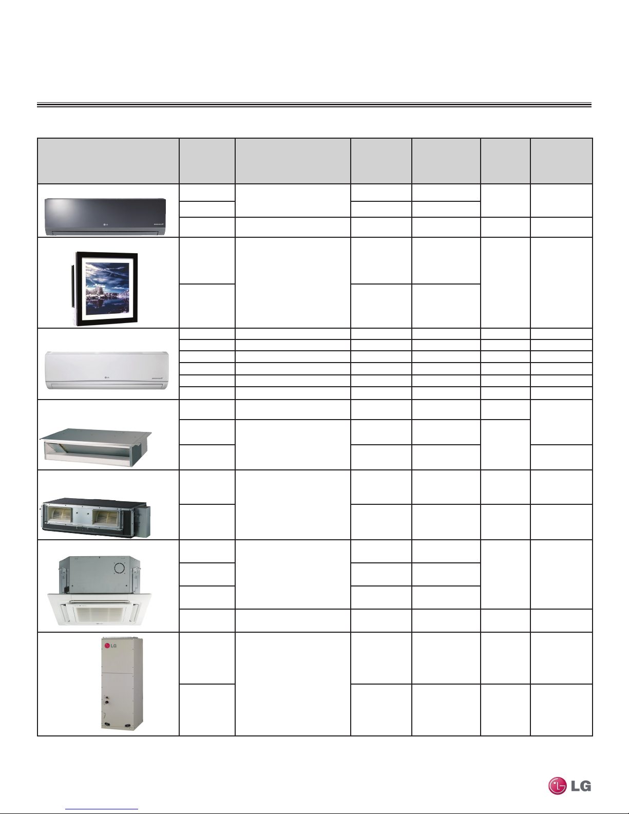
Indoor Unit Overview ..................................................................8
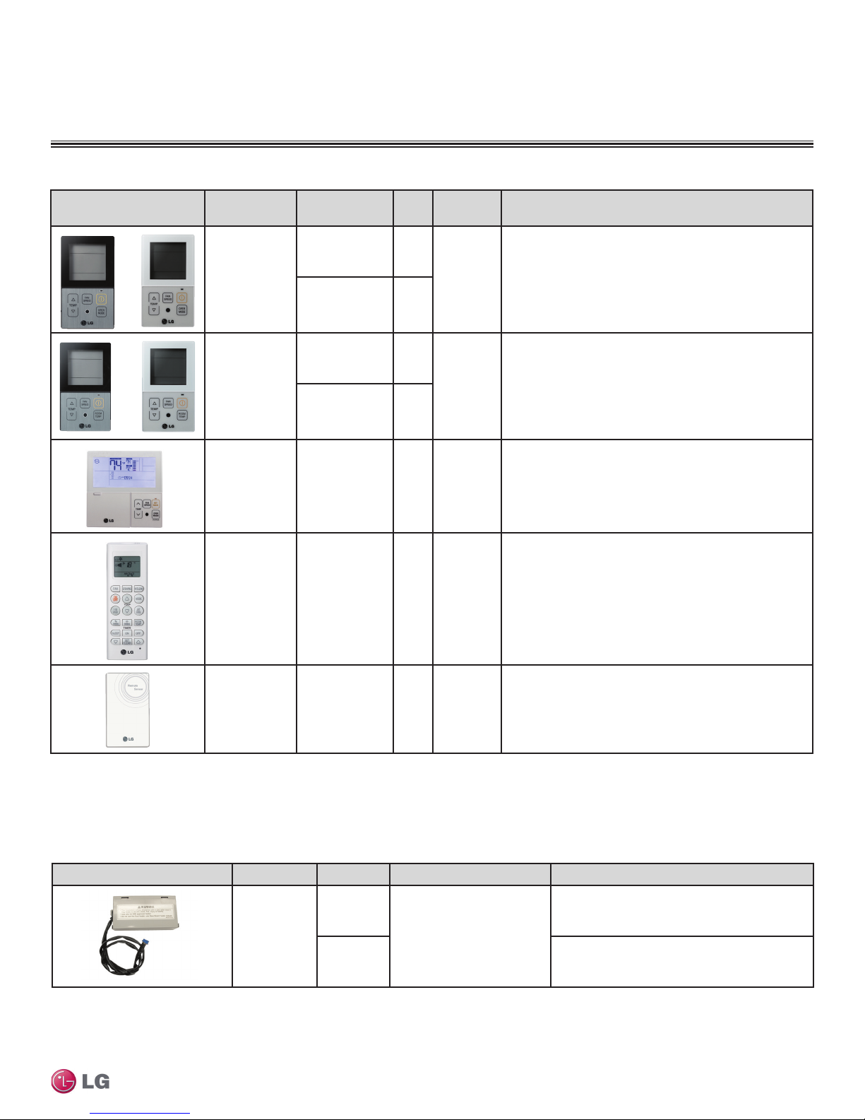
Controls and Options Overview.................................................9
Art Cool Mirror Indoor Units.....................................................16
Mechanical Specications and Features...........................................16
General Data / Specications............................................................17
Dimensions........................................................................................18
Cooling Capacity Table......................................................................20
Heating Capacity Table......................................................................22
Acoustic Data ....................................................................................23
Air Velocity and Temperature Distribution..........................................25
Refrigerant Flow Diagram.................................................................. 26
Wiring Diagram..................................................................................27
Factory Supplied Parts and Materials................................................ 29
Installation and Best Layout Practices............................................... 30
Art Cool Gallery Indoor Units...................................................38
Mechanical Specications and Features...........................................38
General Data / Specications............................................................39
Dimensions........................................................................................40
Cooling Capacity Table......................................................................41
Heating Capacity Table......................................................................42
Acoustic Data ....................................................................................43
Air Velocity and Temperature Distribution..........................................44
Refrigerant Flow Diagram.................................................................. 45
Wiring Diagram..................................................................................46
Factory Supplied Parts and Materials................................................ 47
Installation and Best Layout Practices............................................... 48
Standard Wall-Mounted Indoor Units ......................................58
Mechanical Specications and Features...........................................58
General Data / Specications............................................................59
Dimensions........................................................................................60
Cooling Capacity Table......................................................................64
Heating Capacity Table......................................................................67
Acoustic Data ....................................................................................69
Air Velocity and Temperature Distribution..........................................71
Refrigerant Flow Diagram.................................................................. 74
Wiring Diagram..................................................................................75
Factory Supplied Parts and Materials................................................ 79
Installation and Best Layout Practices............................................... 80
Duct (Low Static) Indoor Units.................................................90
Mechanical Specications and Features...........................................90
General Data / Specications............................................................91
Dimensions........................................................................................92
Cooling Capacity Table......................................................................93
Heating Capacity Table......................................................................95
External Static Pressure....................................................................96
Acoustic Data ....................................................................................97
Refrigerant Flow Diagrams................................................................98
Wiring Diagram................................................................................100
Factory Supplied Parts and Materials.............................................. 101
Installation and Best Layout Practices............................................. 102
Duct (High Static) Indoor Units .............................................. 112
Mechanical Specications and Features......................................... 112
General Data / Specications.......................................................... 113
Dimensions...................................................................................... 114
Cooling Capacity Table.................................................................... 115
Heating Capacity Table.................................................................... 116
External Static Pressure / Acoustic Data ......................................... 117
Refrigerant Flow Diagrams.............................................................. 118
Wiring Diagrams.............................................................................. 119
Factory Supplied Parts and Materials / Installation .........................120
Installation and Best Layout Practices............................................. 121
Four-Way Ceiling Cassette Indoor Units...............................130
Mechanical Specications and Features.........................................130
General Data / Specications..........................................................131
Dimensions......................................................................................132
Dimensions......................................................................................133
Cooling Capacity Table....................................................................134
Heating Capacity Table....................................................................136
Acoustic Data ..................................................................................138
Air Velocity and Temperature Distribution........................................140
Refrigerant Flow Diagram................................................................ 142
Wiring Diagram................................................................................143
Factory Supplied Parts and Materials.............................................. 144
Installation and Best Layout Practices............................................. 145
Vertical-Horizontal Indoor Units.............................................154
Mechanical Specications and Features.........................................154
General Data / Specications..........................................................155
Dimensions......................................................................................156
Cooling Capacity Table....................................................................157
Heating Capacity Table....................................................................158
External Static Pressure..................................................................159
Acoustic Data ..................................................................................160
Refrigerant Flow Diagram................................................................ 161
Wiring Diagram................................................................................162
Factory Supplied Parts and Materials.............................................. 164
Installation and Best Layout Practices............................................. 165
Application Guidelines............................................................174
Equipment Selection Procedure......................................................174
Building Ventilation Design Guide ...................................................180
Placement Considerations............................................................... 185
Refrigerant Piping Design ......................................................192
Design Guideline Summary.............................................................192
Design Guideline Summary.............................................................193
Creating a Balanced System / Manual Layout Procedure 194
LG Engineered Multi F MAX Y-Branch Kit .......................................195
Refrigerant Charge..........................................................................196
Installation & Layout Best Practices .....................................199
Selecting Field-Supplied Copper Tubing .........................................199
Refrigerant Piping System Layout...................................................200
Piping Insulation ..............................................................................208
Condensate Drain Piping................................................................. 209
Y-Branch Kit..................................................................................... 211
Wiring Connections.................................................................214
General Information.........................................................................214
Power Wiring (208-230V) and
Communications Cable Details .......................................................217
Indoor Unit Group Control ...............................................................222
Acronyms.................................................................................223

Due to our policy of continuous product innovation, some specications may change without notication.
©LG Electronics U.S.A., Inc., Englewood Cliffs, NJ. All rights reserved. “LG” is a registered trademark of LG Corp.
4|INTRODUCTION
Multi F and Multi F MAX Indoor Unit Engineering Manual
About LG Electronics, Inc.
LG Electronics, Inc. is a global leader and technology innovator
in consumer electronics, mobile communications, and home
appliances, employing more than 213,000 people in more than 60
countries worldwide. LG Electronics, Inc. comprises five
business units—Home Entertainment, Mobile Communications, Air
Conditioning, Business Solutions, and Home Appliance. LG is one
of the world’s leading producers of flat panel televisions, audio and
video products, mobile handsets, air conditioners, and washing
machines. LG’s commercial air conditioning business unit was estab-
lished in 1968 and has built its lineup of residential and commercial
products to include VRF, Multi F, duct-free split systems, packaged
terminal air conditioners (PTACs), and room air conditioners. In
2011, the air conditioning and energy solutions business unit grew to
include LED lighting and solar products. For more information, visit
www.lg-dfs.com.
Multi-Zone Systems
LG HVAC systems offer a range of solutions that are cost efficient,
quiet and attractive. Multi-zone systems are “split” into indoor and
outdoor units, and provide a smart alternative to both central HVAC
and window-mounted air conditioners. These inverter heat pump
systems are available in a variety of configurations to suit differ-
ent cooling and heating situations. Installation by a qualified HVAC
contractor is safe and easy – little to no duct work or sheet metal is
required.
Multi F Systems
LG’s inverter heat pumps can support two, three, or four indoor
units that are typically installed in separate rooms. Each indoor unit
includes its own remote control, allowing the customer to set the
temperature individually. Indoor units are available in several differ-
ent congurations: Art Cool™ Mirror wall-mounted, Art Cool Gallery
wall-mounted, standard wall-mounted, four-way ceiling cassettes,
ceiling-concealed duct (high and low static), and vertical-horizontal air
handling models. Multi F MAX systems, released in 2012, can oper-
ate up to eight indoor units through two-, three-, or four-port branch
distribution units.
Adaptable and Flexible
Multi F outdoor units can be adapted to a wide range of building ap-
plications and sizes such as schools, hotels, hospitals, ofces, and
residences. The system components are lightweight and compact so
they can be placed in buildings without expensive cranes, they easily
fit into most service elevators, and they can be set in place with
minimal structural reinforcements requirements.
Multi F technology allows you to pipe farther by reaching areas of the
building that would require the installation of a second system when
using traditional direct-expansion cooling and heating equipment. Multi
F provides the designer with uncompromised pipe system engineering
exibility—long pipe runs and large elevation differences. Whether your
building is a condominium, a hotel, a school, or an ofce complex, Multi
F is best suited to reach the farthest corners and elevations.
Smaller Chases and Plenums
LG Multi F systems use refrigerant piping to move heat, resulting in
smaller space requirements for piping as compared to chilled water
or roof top systems. This helps reduce the overall construction and
material cost of the building, and gives back leasable space. Flexible
and logical placement of system components, reduced back-and-
forth pipe lengths, and fewer joints lowers installation costs and
minimizes potential leaking.
Quality Commitment
LG is committed to the success
of DFS projects. We provide
technical support during instal-
lation and commissioning. LG
offers a variety of classes
designed for installers and
servicers on Multi F installa-
tion. Classes are conducted
at LG’s training centers and in
field locations at various times
throughout the year and upon
special request.
Benefits of Multi F Systems
• Individual zone control
• Long refrigerant piping lengths
• High refrigerant piping elevation differences
• Maximum flexibility
• Operating ranges of 14°F to 118°F (DB) in cooling and -4°F to
64°F (WB) in heating
• Quiet and comfortable environment
• Reduced ductwork
CONVERGENCE OF TECHNOLOGY,
INNOVATION, FLEXIBILITY, & STYLE
MULTI F

PRODUCT
INTRODUCTION
“Unit Nomenclature” on page 6
“Outdoor Unit Overview” on page 7
“Indoor Unit Overview” on page 8
“Controls and Options Overview” on page 9

Due to our policy of continuous product innovation, some specications may change without notication.
©LG Electronics U.S.A., Inc., Englewood Cliffs, NJ. All rights reserved. “LG” is a registered trademark of LG Corp.
6|INTRODUCTION
Multi F and Multi F MAX Indoor Unit Engineering Manual
MULTI FMAX
MULTI F
UNIT NOMENCLATURE
Multi-Zone Systems —Indoor Units and Outdoor Units
MAN 12 7HVT
Generation
Features:
H = Heat Pump
V = Inverter
T = High Wall-Mounted Indoor Unit
P = Art Cool Gallery Indoor Unit
Nominal Capacity
(Nominal cooling capacity in Btu/h):
Component:
AN: Art Cool™ Wall-Mounted Indoor Unit
N: Standard Wall-Mounted Indoor Unit
CN: Four-Way Ceiling-Cassette Indoor Unit
DN: Ceiling-Concealed Duct (Low Static) Indoor Unit
HN: Ceiling-Concealed Duct (High Static) Indoor Unit
VN: Vertical-Horizontal Air Handling Indoor Unit
U: Outdoor Unit
L = LG
07 = 7,000
09 = 9,000
12 = 12,000
15 = 15,000
18 = 18,000
24 = 24,000
36 = 36,000
54 = 54,000
L
Type: M = Multi-Zone
Branch Distribution Units
MBD 36
BD: Branch Distribution Unit
P = Part (Accessory)
P
Type: M = Multi-Zone
Family
Number of Port Connections
(Maximum Number of Connectable Indoor Units): 2, 3, 4
Generation: 0, 1
02
• Voltage for all equipment is 208-230V, 60 Hz, 1-phase.
• All indoor units are compatible with wired controllers
• All outdoor units are LGAP control network compatible with PI-485 V-net Control Integration Board (PMNFP14A1, sold separately).
• Compatible single zone IDU nomenclature is listed in the Single Zone Wall-Mounted IDU Engineering Manual.

Due to our policy of continuous product innovation, some specications may change without notication.
©LG Electronics U.S.A., Inc., Englewood Cliffs, NJ. All rights reserved. “LG” is a registered trademark of LG Corp. INTRODUCTION | 7
Introduction
MULTI FMAX
MULTI F
OUTDOOR UNIT OVERVIEW
1Model number shows nominal capacity and frame size designator.
2Nominal capacity rating obtained with air entering the indoor unit at 80ºF dry bulb (DB) and 67ºF wet bulb (WB) and outdoor ambient conditions of 95ºF dry bulb (DB) and 75ºF wet bulb (WB).
3Minimum number of connectable indoor units is two (2).
Outdoor Unit Type Model Number1
Dimensions
(W x H x D)
(inches)
Nominal Cooling
Capacity Btu/h2
Net
Weight
(lbs.)
No. of
Connectable
Indoor Units3
Pipe Connections
(inches, O.D.)
(Liquid, Vapor)
Multi F Dual-Zone
LMU18CHV 34-1/4 x 25 25/32 x 12-19/32 18,000 99 2-2 1/4 x 2 Each,
3/8 x 2 Each
Multi F Tri-Zone
LMU24CHV 34-1/4 x 25 25/32 x 12-19/32 24,000 99 2-3 1/4 x 3 Each,
3/8 x 3 Each
Multi F Quad-Zone
LMU36CHV 37-13/32 x 32-27/32 x 13 36,000 137 2-4 1/4 x 4 Each,
3/8 x 4 Each
Multi F MAX Eight-Zone
LMU540HV 37-13/32 x 54-11/32 x 13 54,000 214 2-8 3/8 x 1 Each,
3/4 x 1 Each
Table 1: Summary Data—Multi F / Multi F MAX Outdoor Units

Due to our policy of continuous product innovation, some specications may change without notication.
©LG Electronics U.S.A., Inc., Englewood Cliffs, NJ. All rights reserved. “LG” is a registered trademark of LG Corp.
8|INTRODUCTION
Multi F and Multi F MAX Indoor Unit Engineering Manual
MULTI FMAX
MULTI F
INDOOR UNIT OVERVIEW
1Model number shows nominal capacity and frame size designator.
2Nominal capacity rating obtained with air entering the indoor unit at 80ºF dry bulb (DB) and 67ºF wet bulb (WB) and outdoor ambient conditions of 95ºF dry bulb (DB) and 75ºF wet bulb (WB).
3H/M/L = High/Medium/Low.
Indoor Unit Type Model
Number1
Dimensions
(W x H x D)
(inches)
Nominal
Cooling
Capacity Btu/h2
Air Flow Rate
(CFM)
(H/M/L3)
Net
Weight
(lbs.)
Pipe
Connections
(inches, O.D.)
(Liquid, Vapor)
Art CoolTM Mirror Wall-Mounted LMAN097HVT 35-1/4 × 11-3/8 × 8-1/16 9,000 247 / 230 / 212 25 1/4, 3/8
LMAN127HVT 12,000 335 / 318 / 300
LMAN187HVT 40-9/16 x 12-25/32 x 9-21/32 18,000 572 / 501 / 434 35 1/4, 1/2
Art CoolTM Gallery Wall-Mounted
LMAN097HVP
23-5/8 x 23-5/8 x 5-25/32
9,000 272 / 208 / 155
32 1/4, 3/8
LMAN127HVP 11,200 314 / 258 / 198
Standard Wall-Mounted LMN077HVT 35-1/4 x 11-3/8 x 8-9/32 7,000 198 / 177 / 162 23 1/4, 3/8
LSN090HSV4 34-7/8 x 11-1/4 x 8-1/4 9,000 247 / 230 / 212 20 1/4, 3/8
LSN120HSV4 34-7/8 x 11-1/4 x 8-1/4 12,000 335 / 318 / 300 20 1/4, 3/8
LMN157HVT 35-1/4 x 11-3/8 x 8-9/32 14,300 371 / 318 / 247 23 1/4, 3/8
LSN180HSV4 40-9/16 x 12-13/16 x 9-13/16 18,000 572 / 501 / 434 31 3/8, 5/8
LMN247HVT 40-9/16 x 12-25/32 x 9-27/32 24,000 720 / 600 / 466 32 1/4, 1/2
Ceiling-Concealed Duct
(Low Static) LMDN096HV 27-9/16 x 7-15/32 x 27-9/16 9,000 318 / 247 / 194 39
1/4, 3/8
LMDN126HV
35-7/16 x 7-15/32 x 27-9/16
12,000 353 / 300 / 247
51
LMDN186HV 18,000 530 / 441 / 353 1/4, 1/2
Ceiling-Concealed Duct
(High Static) LMHN240HV
46-17/32 x 11-23/32 x 17-23/32
24,000 688 / 618 / 530 80 1/4, 1/2
LMHN360HV 36,000 1,130 / 953 / 706 91 3/8, 5/8
Four-Way Ceiling-Cassette LMCN077HV
Body: 22-7/16 x 8-7/16 x 22-7/16
Panel: 27-9/16 x 7/8 x 27-9/16
7,000 265 / 212 / 177
31 (Body),
7 (Panel) 1/4, 3/8LMCN097HV 9,000 300 / 265 / 230
LMCN125HV 12,000 335 / 283 / 247
LMCN185HV Body: 22-7/16 x 10-3/32 x 22-7/16
Panel: 27-9/16 x 7/8 x 27-9/16 18,000 459 / 424 / 388 34 (Body),
7 (Panel) 1/4, 1/2
Vertical-
Horizontal
Air Handling LMVN240HV
18 x 48-21/32 x 21-1/4
24,000 710 / 640 / 480 117 1/4, 1/2
LMVN360HV 36,000 990 / 880 / 800 121 3/8, 5/8
Table 2: Summary Data—Multi F Indoor Units.

Due to our policy of continuous product innovation, some specications may change without notication.
©LG Electronics U.S.A., Inc., Englewood Cliffs, NJ. All rights reserved. “LG” is a registered trademark of LG Corp. INTRODUCTION | 9
Introduction
MULTI FMAX
MULTI F
CONTROLS AND OPTIONS OVERVIEW
Zone Controller Name Model / Part No. Case
Color
Max. Wire
Length (ft.) Description
Simple Controller
with Mode
Selection
PQRCVCL0 Black
164
Allows control of indoor unit ON / OFF, operation mode, fan
speed, and temperature setpoint for up to 16 indoor units.
Included with Ceiling-Concealed Duct (High Static and Low
Static1) and Vertical-Horizontal Air Handling1indoor units;
optional accessory for all other indoor unit types.
AKB729558161White
Simple Controller
without Mode
Selection
PQRCHCA0 Black
164 Allows control of indoor unit ON / OFF, fan speed, and
temperature setpoint for up to 16 indoor units.
PQRCHCA0QW White
LG 7-Day
Programmable
Thermostat
PREMTB10U White 164
Allows control of indoor unit ON / OFF, operation mode,
occupied / unoccupied temperature setpoints, fan speed, and
airflow direction for up to 16 indoor units. Programmable
schedule with five events per day.
Wireless
Controller
AKB736356063
AKB736356074
AKB738353125
AKB737576046
Ivory -
Allows control of indoor unit ON / OFF, operation mode, fan
speed, and temperature setpoint. Also provides subfunction
control. Included with Art Cool Mirror3and Gallery4 Wall-
Mounted, Standard HVT3 Wall-Mounted, Standard HSV5
Wall-Mounted, and Four-Way Cassette6 indoor units; optional
accessory for Duct and Vertical-Horizontal AHU with use of
wired controller.
Wall-Mounted
Remote
Temperature
Sensor
PQRSTA0 Ivory 50
Allows remote temperature measurement for four-way ceiling
cassette, ceiling-concealed duct, and vertical-horizontal air
handling indoor units.
Table 3: Summary Data—Zone Controllers.
1Simple Mode Controllers for the ceiling-concealed duct (high static and low static) and the vertical-horizontal air handling indoor units are also referenced by Model No. PQRCVCL0QW.
Before specifying or placing an order, refer to the V-Net Network Solutions Engineering Product Data Book, and review the detailed technical data provided to fully understand the capabilities and limitations of
these devices.
For information on controller capatibility, refer to the Controls and Options Table on page 12
Table 4: Summary Data—Controller Accessories.
Controller Accessory Name Model No. Description For
Auxiliary Heater
Relay Kit
PRARH0
Adds coordinated control of
an external heater with normal
heat pump operations. Contact
energizes at 2.7°F below
setpoint. De-energizes at
2.7°F above setpoint.
Ceiling-concealed duct (high static and low static)
and four-way ceiling cassette indoor units.
PRARS0 Standard and Art Cool Mirror wall-mounted indoor
units.

Due to our policy of continuous product innovation, some specications may change without notication.
©LG Electronics U.S.A., Inc., Englewood Cliffs, NJ. All rights reserved. “LG” is a registered trademark of LG Corp.
10 |INTRODUCTION
Multi F and Multi F MAX Indoor Unit Engineering Manual
MULTI FMAX
MULTI F
Before specifying or placing an order, refer to the V-Net Network Solutions Engineering Product Data Book, and review the detailed technical data provided to fully understand the capabilities and limitations of
these devices.
For information on controller capabilities, refer to the Controls and Options Table on page 12.
Specialty Application
Device Name Model No. Connects
to Application Binary Signals
Input / Output Description
Dry Contact Unit
24 VAC PQDSB1
Indoor
Unit
ON / OFF, Run Status,
Error Status 1 / 2 Enables the indoor unit to be
controlled and monitored by
third-party controls using
binary inputs and outputs.
Dry Contact Unit
for Setback PQDSBC
ON / OFF, Mode, Controller
Lock, Power Save, Run
Status, Error Status
2 / 2
Dry Contact Unit
for Thermostat PQDSBNGCM1
ON / OFF, Thermo ON /
OFF, Mode, Fan Speed,
Run Status, Error Status
—
Enables the indoor unit to be
controlled and monitored by a
third-party thermostat or controller.
PI-485 V-net
Control
Integration
Board
PMNFP14A1 Outdoor
Unit — —
Control integration to LG V-net
controls (AC Smart Premium, ACP,
BACnet, LonWorks, etc.)
Power
Distribution
Indicator (PDI)
Premium
PQNUD1S41 Comm.
BUS
Energy Consumption
Monitoring 8 / 0
Monitors total outdoor unit power
consumption for up to eight
systems, and distributes per
indoor unit based on weighted
calculation.
Table 5: Summary Data— Zone Controller Communication Cables.
CONTROLS AND OPTIONS OVERVIEW
Table 6: Summary Data—Specialty Application Devices.
Before specifying or placing an order, refer to the V-Net Network Solutions Engineering Product Data Book, and review the detailed technical data provided to fully understand the capabilities and limitations of
these devices.
For information on controller capabilities, refer to the Controls and Options Table on page 12.
Communication Cable Name Model No. Max. Wire
Length (ft.) Description
Wired Remote Group Control
Cable Assembly PZCWRCG3 32 Required when grouping multiple indoor units with a
single zone controller.
Wired Remote / Group Control
Extension Cable PZCWRC1 32
Increases the distance between a remote controller
and an indoor unit, or between indoor units in a control
group.

Due to our policy of continuous product innovation, some specications may change without notication.
©LG Electronics U.S.A., Inc., Englewood Cliffs, NJ. All rights reserved. “LG” is a registered trademark of LG Corp. INTRODUCTION | 11
Introduction
MULTI FMAX
MULTI F
Table 7: Summary Data—Central Controllers (Connect to the Outdoor Unit Through the PI-485 Board (accessory, sold separately).
Central Controller Name Model No.
Devices
per
Controller
Systems
per
Comm.
BUS
Devices
per Comm.
BUS
No. of
Comm.
BUS
ports
Binary
Signals
Input /
Output
Power /
Connection Description
AC Smart
Premium PQCSW421E0A 128 16 128 1 2 DI /
2 DO 24 VAC
Provides for scheduling,
auto-changeover, setback,
remote controller lock,
setpoint range limit, run
time limit, web access,
email alarm notification,
visual floorplan navigation,
peak/demand control,
software device interlocking,
PDI integration, and AC
Manager Plus integration
advanced functionality in
addition to basic unit control
and monitoring.
AC Ez PQCSZ250S0 32 16 256 1 —
12 VDC /
Outdoor
Unit
Provides for scheduling in
addition to basic indoor unit
control and monitoring.
Advanced Control
Platform (ACP)
Standard
PQCPC22N1 256 16
64 (128
with PDI
Premium)
4
2 / 2 24 VAC
Provides for scheduling,
remote controller lock, setpoint
range limit, web access, peak
/ demand control, PDI
integration, and AC Manager
Plus integration advanced
functionality in addition to
basic unit control and
monitoring.
Advanced Control
Platform (ACP)
Premium
PQCPC22A1 256 16
64 (128
with PDI
Premium)
10 / 4 24 VAC
Before specifying or placing an order, refer to the V-Net Network Solutions Engineering Product Data Book, and review the detailed technical data provided to fully understand the capabilities and limitations of
these devices.
For information on controller capabilities, refer to the Controls and Options Table on page 12.
Table 8: Summary Data—Integration Solutions (Connect to Outdoor Unit Through the PI-485 Board (accessory, sold separately).
Central Controller Name Model No.
Devices
per
Controller
Systems
per
Comm.
BUS
Devices
per Comm.
BUS
No. of
Comm.
BUS
ports
Binary
Signals
Input /
Output
Power /
Connection Description
BACnet®Gateway PQNFB17C1 256 16
64 (128
with PDI
Premium)
4 2 / 2 24 VAC Allow integration of LG
equipment for control
and monitoring by open
protocol BACnet and
LonWorks building
automation and controls
systems.
LonWorks®Gateway PLNWKB100 64 16
64 (128
with PDI
Premium)
1 2 / 2 24 VAC
Before specifying or placing an order, refer to the V-Net Network Solutions Engineering Product Data Book, and review the detailed technical data provided to fully understand the capabilities and limitations of
these devices.
For information on controller capabilities, refer to the Controls and Options Table on page 12.
CONTROLS AND OPTIONS OVERVIEW

Due to our policy of continuous product innovation, some specications may change without notication.
©LG Electronics U.S.A., Inc., Englewood Cliffs, NJ. All rights reserved. “LG” is a registered trademark of LG Corp.
12 |INTRODUCTION
Multi F and Multi F MAX Indoor Unit Engineering Manual
MULTI FMAX
MULTI F
CONTROLS AND OPTIONS OVERVIEW
Table 9: Indoor Units—Functions, Controls and Options.
Indoor Unit Type
ART COOL™
Mirror Wall
Mounted
ART COOL™
Gallery
Standard Wall
Mounted
Ceiling
Concealed
(Low Static)
Ducted
Ceiling
Concealed
(High Static)
Ducted
Four-Way
Ceiling
Cassette
Vertical-
Horizontal Air
Handling Unit
Airow
Air supply outlets 1311241
Airflow direction (left/right) Auto Auto Auto
Airflow direction (up/down) Auto Auto Auto Auto
Auto swing (left/right) √√√
Auto swing (up/down) √ √ √ √
Airflow steps (fan/cool/heat) 6 / 6 / 5 5 / 5 / 4 6 / 6 / 5 3 / 3 / 3 3 / 3 / 3 4 / 5 / 4 3 / 3 / 3
Chaos wind (random fan speed) √ √ √ √
Jet-cool √ √ √ √
Swirl wind √
Filter
Washable anti-fungal1√√√√√√
Plasma2√ √ o3
3M HAF2√
Ventilation √4
Operation
Drain pump √√√
E.S.P. control √ √ √
Electric heater o
High ceiling √
Hot Start √√√√√√√
Self diagnostics √√√√√√√
Soft Dry (dehumidification) √√√√√√√
Auto operation √√√√√√√
Auto clean (coil dry) √√√
Auto restart √√√√√√√
Child lock ooooooo
Forced operation √ √ √ √
Group control – Requires the use
of one Group control Cable Kit
(PZCWRCG3) for every
additional indoor unit
ooooooo
Sleep mode √√√√√√√
Timer (on/off) √√√√√√√
Weekly schedule ooo√ √ o√
Two thermistor control ooooooo
Controllers
7-Day programmable controller ooooooo
Simple wired remote controller ooo√ √ o√
Wireless LCD remote control √√√o5o5√o5
Dry contact ooooooo
Dry contact (temperature setting) ooooooo
Central control (LGAP) √√√√√√√
Connector for Water Sensor √√√
1Primary washable filters.
2Secondary filter (plasma: HVT wall-mount and cassette; 3M: HSV4)
3Branch location and static pressure requirements. Requires PTPKQ0
Plasma kit.
4Requires ventilation kit PTVK430 (Temperature, humidity, and volume
limitations apply).
5Requires wired zone controller.
√ = Standard feature
o = Unit option

Due to our policy of continuous product innovation, some specications may change without notication.
©LG Electronics U.S.A., Inc., Englewood Cliffs, NJ. All rights reserved. “LG” is a registered trademark of LG Corp. INTRODUCTION | 13
Introduction
MULTI FMAX
MULTI F
CONTROLS AND OPTIONS OVERVIEW
Table 11: Indoor Unit Accessories Overview.
Multi F MAX Accessory Name Model No. Description
Two-Port Branch Distribution Unit PMBD3620
Distributes refrigerant from Multi F MAX outdoor unit from
one (1) to two (2) indoor units (maximum 24,000 Btu/h for
each port).
Three-Port Branch Distribution Unit PMBD3630
Distributes refrigerant from Multi F MAX outdoor unit from
one (1) to three (3) indoor units (maximum 24,000 Btu/h for
each port).
Four-Port Branch Distribution Unit
PMBD3640
Distributes refrigerant from Multi F MAX outdoor unit from
one (1) to four (4) indoor units (maximum 24,000 Btu/h for
each port).
PMBD3641
Distributes refrigerant from Multi F MAX outdoor unit from
one (1) to four (4) indoor units (maximum 24,000 Btu/h for
ports A,B,C; maximum 36,000 Btu/h for D port).
Y-branch Kit PMBL5620 Y-branch Kit for Multi F MAX outdoor unit to connect up to
two (2) branch distribution units.
Model No. Description
For Four-Way Ceiling-Cassette Indoor Units
PT-UQC Ceiling Grille
PTPKQ0 Plasma Kit
PTVK430 Ventilation Kit
For Vertical-Horizontal Air Handing Units
ANEH053B1 5 kW Electric Heater
ANEH103B2 10 kW Electric Heater
For Ceiling-Concealed Duct (High Static) Indoor Units
ZFBXBG01A High Efficiency Filter Box
ZFBXD201A Dynamic V8 2VL Low Profile Air Cleaner
ZPLMV201A Dynamic 2VL Air Cleaner Low Profile Return Air Plenum
ZFBXD402A Dynamic V8 4VL Low Profile Air Cleaner
ZPLMV402A Dynamic 4VL Air Cleaner Low Profile Return Air Plenum
ZFLT1301A 4-Pack Dynamic V8 VL Air Cleaner Replacement Filter Pads
ZFLT1302A 24-Pack Dynamic V8 VL Air Cleaner Replacement Filter Pads
ZGRLRA01A Dynamic V8 Air Cleaner Louvered Return Air Grille (one per plenum )
ZGRLRA02A Dynamic V8 Air Cleaner Egg Crate Return Air Grille (one per plenum)
Table 10: Multi F MAX Outdoor Unit Accessories Overview.
Ø3/4 Gas
Ø3/8 Liquid

Due to our policy of continuous product innovation, some specications may change without notication.
©LG Electronics U.S.A., Inc., Englewood Cliffs, NJ. All rights reserved. “LG” is a registered trademark of LG Corp.
14 |INTRODUCTION
Multi F and Multi F MAX Indoor Unit Engineering Manual
MULTI FMAX
MULTI F

“Mechanical Specifications” on page 16
“General Data / Specifications” on page 17
“Dimensions” on page 18
“Cooling Capacity Table” on page 20
“Heating Capacity Table” on page 22
“Acoustic Data” on page 23
“Air Velocity and Temperature Distribution” on page 24
“Refrigerant Flow Diagram” on page 26
“Wiring Diagram” on page 27
“Factory Supplied Parts and Materials” on page 29
“Installation and Best Layout Practices” on page 30
ART COO
L™
MIRROR
INDOOR UNIT DATA

ART COOL Mirror Wall-Mounted
Indoor Units
General
All LG indoor units are factory assembled, wired, piped, and pro-
vided with a control circuit board, fan, and motor. ART COOL Mirror
Wall-Mounted indoor units have a sound rating no higher than 39
dB(A) as tested per KSA0701 ISO Standard 3745.
Coil
Indoor unit coils are comprised of a minimum of two rows of
aluminum fins mechanically bonded to copper tubing. The coils are
pressure tested at the factory. Each unit is provided with a factory
installed condensate drain pan below the coil.
Refrigerant System
System is designed for use with R410A refrigerant. The refrigeration
circuit is pressure-tested at the factory and shipped with a holding
charge of helium gas. Refrigerant pipe connections are 45° flare.
All refrigerant lines from the outdoor unit to the indoor units must be
field insulated.
Electrical
Each indoor unit is designed to operate using 208–230/60/1 power
with voltage variances of ±10%.
Casing
Units are designed to mount on a vertical surface, and are shipped
with a separate back plate that secures the unit to the wall, protrud-
ing no more than ten (10) inches. Unit is designed so that refrigerant
piping can be installed in one (1) of four (4) different directions.
Finish
The Art Cool Mirror unit has a flat, architectural panel with a smoked
charcoal mirror finish. Unit casing has a dark grey finish and is
manufactured of heavy-duty acrylonitrile butadiene styrene (ABS)
and high impact polystyrene (HIPS) plastic.
Fan Assembly and Control
The unit has a single, direct-drive, crossow fan made of high
strength ABS plastic. The fan motor is brushless digitally controlled
(BLDC) with permanently lubricated and sealed ball bearings. The fan
/ motor assembly is mounted on vibration attenuating rubber grom-
mets. Fan speed is controlled using a microprocessor-based direct
digitally controlled algorithm that provides pre-programmed, eld-
selectable xed or auto fan speeds in the Heating and Cooling
modes. For Art Cool Mirror Wall-Mounted units, the indoor fan has
Low, Med, High, Power Cool and Auto settings for Cooling mode; and
has Low, Med, High, and Auto settings for Heating mode. The Auto
setting adjusts the fan speed based on the difference between the
controller setpoint and space temperature. Also, the separate Chaos
setting provides a simultaneous and random change in fan speed and
ow direction at the discharge, simulating a natural outdoor breeze.
Air Filter
Return air inlet has a factory-supplied primary removable, washable
filter. The unit is also equipped with a secondary plasma filter. Filters
are accessed from the front of the unit without the use of tools.
Airflow Guide Vanes
A motorized guide vane is factory installed, and allows the ability to
control the direction of airflow from side to side. A motorized louver
provides an automatic change in airflow by directing the air up and
down to provide uniform air distribution.
Microprocessor Control
The indoor unit is provided with an integrated control panel to com-
municate with the outdoor unit. All unit operation parameters are
stored in non-volatile memory resident on the unit microprocessor.
The microprocessor controls space temperature through using the
value provided by the temperature sensor within the indoor unit.
The microprocessor control will activate indoor unit operation when
the indoor room temperature falls below or rises above a setpoint
temperature, at which point, a signal is sent to the outdoor unit to
begin the appropriate mode. The microprocessor will also provide
self-diagnostics and auto restart functions. A field-supplied four-
wire power / communications cable must be installed to connect the
indoor unit(s) to the outdoor unit.
Controls
The indoor unit casing has a factory-standard, integral infrared
sensor designed to communicate with the supplied LG wireless
handheld remote controller. An optional LG supplied wired controller
is available as an additional accessory. Communication between the
indoor units and the outdoor unit is accomplished through 18 AWG,
four-core, stranded and shielded power / communication cable.
Condensate
The unit is designed for gravity draining of condensate and includes
a flexible drain hose capable of installation in one of two directions.
Unit includes a connection that is compatible with the AquaGuard®
AG-9300-LG condensate sensor.
Figure 1: Multi F Art Cool Mirror Wall-Mounted Indoor Unit.
ART COOL MIRROR INDOOR UNITS
Mechanical Specications and Features
• Inverter (Variable speed fan)
• Chaos swing
• Plasma filter
• Jet cool
• Group Control
• Self-cleaning indoor coil
• Auto operation
• Auto restart operation
• Dehumidifying function
• Self diagnosis function
• Wireless LCD remote control included; wired
thermostat available (sold separately)
Features
Due to our policy of continuous product innovation, some specications may change without notication.
©LG Electronics U.S.A., Inc., Englewood Cliffs, NJ. All rights reserved. “LG” is a registered trademark of LG Corp.
16 |ART COOL MIRROR
Multi F and Multi F MAX Indoor Unit Engineering Manual
MULTI FMAX
MULTI F

Model Name LMAN097HVT LMAN127HVT LMAN187HVT
Nominal Cooling Capacity (Btu/h)19,000 12,000 18,000
Nominal Heating Capacity (Btu/h)110,400 13,800 20,800
Operating Range
Cooling (°F WB) 57-77 57-77 57-77
Heating (°F DB) 59-81 59-81 59-81
Fan
Type Cross Flow Cross Flow Cross Flow
Motor Output (W) x Qty. 14.4 x 1 14.4 x 1 76.0 x 1
Motor/Drive Brushless Digitally Controlled /
Direct
Brushless Digitally Controlled /
Direct
Brushless Digitally Controlled /
Direct
Airflow Rate CFM (H/M/L) 247 / 230 / 212 335 / 318 / 300 572 / 501 / 434
Unit Data
Refrigerant Type2R410A R410A R410A
Refrigerant Control EEV EEV EEV
Power Supply V, Ø, Hz3208-230, 1, 60 208-230, 1, 60 208-230, 1, 60
Rated Amps (A) 0.2 0.2 0.3
Sound Pressure Level ±3 dB(A) (H/M/L)433 / 30 / 27 39 / 36 / 31 37 / 33 / 28
Dimensions (W x H x D, in.) 35-1/4 x 11-3/8 x 8-1/16 35-1/4 x 11-3/8 x 8-1/16 40-9/16 x 12-25/32 x 9-21/32
Net Unit Weight (lbs.) 25 25 35
Shipping Weight (lbs.) 29 29 40
Power Wiring / Communications Cable
(No. x AWG)54 x 18 4 x 18 4 x 18
Heat Exchanger
(Row x Column x Fin / inch) x Number (2 x 16 x 23) x 1 (2 x 16 x 23) x 1 (3 x 18 x 22) x 1
Piping
Liquid (in.) 1/4 1/4 1/4
Vapor (in.) 3/8 3/8 1/2
Drain O.D. / I.D. (in.) 27/32, 5/8 27/32, 5/8 27/32, 5/8
1Nominal capacity is rated 0 ft. above sea level with corresponding refrigerant piping length in
accordance with standard length of each outdoor unit and a 0 ft. level difference between outdoor and
indoor units. All capacities are net with a combination ratio between 95 – 105%.
Nominal cooling capacity rating obtained with air entering the indoor unit at 80ºF dry bulb (DB) and 67ºF
wet bulb (WB) and outdoor ambient conditions of 95ºF dry bulb (DB) and 75ºF wet bulb (WB).
Nominal heating capacity rating obtained with air entering the indoor unit at 70ºF dry bulb (DB) and 60ºF
wet bulb (WB) and outdoor ambient conditions of 47ºF dry bulb (DB) and 43ºF wet bulb (WB).
2This unit comes with a dry helium charge.
3Acceptable operating voltage: 187V-253V.
4Sound pressure levels are tested in an anechoic chamber under ISO Standard 3745 and are the
same in both cooling and heating mode. These values can increase due to ambient conditions during
operation.
5All power wiring / communications cable to be minimum 18 AWG, 4-conductor, stranded, shielded, and
must comply with applicable local and national codes.
ART COOL MIRROR INDOOR UNITS
General Data / Specications
Table 12: Multi F Art Cool Mirror Indoor Unit General Data.
ART COOL MIRROR | 17
Art Cool Mirror™
Due to our policy of continuous product innovation, some specications may change without notication.
©LG Electronics U.S.A., Inc., Englewood Cliffs, NJ. All rights reserved. “LG” is a registered trademark of LG Corp.
MULTI FMAX
MULTI F

ART COOL MIRROR INDOOR UNITS
Dimensions
Figure 2: LMAN097HVT and LMAN127HVT Dimensions.
Return Air Inlet
Supply Air Va ne
Supply Air Va ne Return Air Inlet
Supply Air Vane
Due to our policy of continuous product innovation, some specications may change without notication.
©LG Electronics U.S.A., Inc., Englewood Cliffs, NJ. All rights reserved. “LG” is a registered trademark of LG Corp.
18 |ART COOL MIRROR
Multi F and Multi F MAX Indoor Unit Engineering Manual
MULTI FMAX
MULTI F

ART COOL MIRROR INDOOR UNITS
Dimensions
Figure 3: LMAN187HVT Dimensions.
Supply Air Vane
Supply Air Vane Return Air Inlet
Return Air Inlet
Supply Air Vane
ART COOL MIRROR | 19
Art Cool Mirror™
Due to our policy of continuous product innovation, some specications may change without notication.
©LG Electronics U.S.A., Inc., Englewood Cliffs, NJ. All rights reserved. “LG” is a registered trademark of LG Corp.
MULTI FMAX
MULTI F

ART COOL MIRROR INDOOR UNITS
Cooling Capacity Table
Model No. /
Nominal Capacity
of Indoor Unit
(Btu/h)
Outdoor Air
Temp.
(°F DB)
Indoor Air Temp. °F DB / °F WB
68 / 57 73 / 61 77 / 64 80 / 67 86 / 72 90 / 75
TC SHC TC SHC TC SHC TC SHC TC SHC TC SHC
LMAN097HVT
9,000
14 8.82 6.04 9.37 6.38 9.92 6.18 10.31 6.31 11.01 6.36 11.56 6.48
20 8.82 6.09 9.36 6.43 9.91 6.23 10.31 6.36 11.01 6.41 11.55 6.53
25 8.81 6.13 9.36 6.48 9.90 6.27 10.30 6.41 11.00 6.46 11.54 6.58
30 8.80 6.18 9.35 6.53 9.90 6.32 10.29 6.46 10.99 6.51 11.54 6.63
35 8.80 6.23 9.34 6.58 9.89 6.37 10.28 6.50 10.98 6.56 11.53 6.68
40 8.79 6.28 9.33 6.63 9.88 6.42 10.27 6.55 10.97 6.61 11.52 6.73
45 8.78 6.32 9.33 6.68 9.87 6.47 10.27 6.60 10.96 6.66 11.51 6.78
50 8.78 6.37 9.32 6.73 9.87 6.51 10.26 6.65 10.96 6.71 11.50 6.83
55 8.77 6.42 9.31 6.78 9.86 6.56 10.25 6.70 10.95 6.76 11.49 6.88
60 8.76 6.46 9.31 6.83 9.85 6.61 10.24 6.75 10.94 6.81 11.48 6.93
65 8.76 6.51 9.30 6.88 9.84 6.66 10.24 6.80 10.93 6.85 11.47 6.98
70 8.75 6.56 9.29 6.92 9.84 6.70 10.23 6.85 10.92 6.90 11.47 7.03
75 8.54 6.45 9.08 6.82 9.62 6.61 10.01 6.75 10.71 6.82 11.25 6.96
80 8.33 6.34 8.87 6.71 9.41 6.51 9.80 6.66 10.49 6.73 11.03 6.87
85 8.12 6.22 8.66 6.60 9.20 6.41 9.59 6.56 10.28 6.64 10.82 6.79
90 7.91 6.10 8.45 6.48 8.99 6.31 9.37 6.46 10.06 6.55 10.60 6.70
95 7.68 6.04 8.22 6.43 8.75 6.26 9.00 6.32 9.83 6.52 10.36 6.67
100 7.50 5.88 8.03 6.26 8.57 6.11 8.88 6.22 9.64 6.37 10.17 6.53
105 7.31 5.72 7.84 6.10 8.38 5.96 8.77 6.12 9.45 6.23 9.99 6.39
110 7.12 5.52 7.66 5.90 8.19 5.78 8.58 5.94 9.26 6.06 9.80 6.22
115 6.94 5.36 7.47 5.74 8.01 5.63 8.39 5.79 9.08 5.91 9.61 6.08
118 6.82 5.32 7.36 5.70 7.89 5.60 8.28 5.76 8.96 5.89 9.50 6.06
122 6.79 5.30 7.32 5.69 7.86 5.59 8.24 5.76 8.93 5.89 9.46 6.06
LMAN127HVT
12,000
14 11.76 8.51 12.49 8.99 13.22 8.70 13.75 8.88 14.69 8.96 15.42 9.13
20 11.75 8.57 12.48 9.06 13.21 8.77 13.74 8.95 14.67 9.03 15.40 9.20
25 11.75 8.64 12.48 9.13 13.20 8.84 13.73 9.02 14.66 9.10 15.39 9.27
30 11.74 8.71 12.47 9.20 13.19 8.90 13.72 9.09 14.65 9.17 15.38 9.34
35 11.73 8.77 12.46 9.27 13.18 8.97 13.71 9.16 14.64 9.24 15.37 9.41
40 11.72 8.84 12.45 9.34 13.17 9.04 13.70 9.23 14.63 9.31 15.36 9.48
45 11.71 8.90 12.44 9.41 13.16 9.11 13.69 9.30 14.62 9.38 15.35 9.55
50 11.70 8.97 12.43 9.47 13.15 9.17 13.68 9.37 14.61 9.45 15.33 9.62
55 11.69 9.03 12.42 9.54 13.14 9.24 13.67 9.44 14.60 9.52 15.32 9.70
60 11.68 9.10 12.41 9.61 13.13 9.31 13.66 9.50 14.59 9.58 15.31 9.77
65 11.67 9.17 12.40 9.68 13.12 9.38 13.65 9.57 14.57 9.65 15.30 9.84
70 11.66 9.23 12.39 9.75 13.11 9.44 13.64 9.64 14.56 9.72 15.29 9.91
75 11.38 9.08 12.11 9.60 12.83 9.31 13.35 9.51 14.27 9.60 15.00 9.79
80 11.10 8.92 11.82 9.45 12.55 9.17 13.07 9.38 13.99 9.48 14.71 9.68
85 10.83 8.76 11.54 9.29 12.26 9.03 12.78 9.24 13.70 9.36 14.42 9.56
90 10.55 8.60 11.26 9.13 11.98 8.88 12.50 9.10 13.42 9.22 14.13 9.43
95 10.25 8.51 10.96 9.05 11.67 8.82 12.00 8.90 13.10 9.18 13.81 9.39
100 10.00 8.28 10.71 8.82 11.42 8.61 11.84 8.76 12.85 8.98 13.56 9.20
105 9.75 8.05 10.46 8.59 11.17 8.40 11.69 8.62 12.60 8.78 13.31 9.01
110 9.50 7.77 10.21 8.31 10.92 8.14 11.44 8.37 12.35 8.53 13.07 8.76
115 9.25 7.54 9.96 8.08 10.67 7.92 11.19 8.15 12.10 8.33 12.82 8.56
118 9.10 7.49 9.81 8.03 10.52 7.88 11.04 8.12 11.95 8.30 12.67 8.54
122 9.05 7.47 9.76 8.01 10.48 7.87 10.99 8.11 11.90 8.29 12.62 8.53
Table 13: Multi F Art Cool Mirror Indoor Units Cooling Capacity Table.
TC = Total Capacity (kBtu/h).
SHC: Sensible Heat Capacity (kBtu/h).
Nominal capacity as rated 0 ft. above sea level and a 0 ft. level difference between outdoor and indoor
units. Corresponding refrigerant piping length is accordance with standard length of each outdoor unit.
Nominal cooling capacity rating obtained with air entering the indoor unit at 80ºF dry bulb (DB) and
67ºF wet bulb (WB), and outdoor ambient conditions of 95ºF dry bulb (DB) and 75ºF wet bulb (WB).
The shaded table columns and rows indicate reference data. When operating at this temperature, these
values can be different if the system is not running consistently.
Due to our policy of continuous product innovation, some specications may change without notication.
©LG Electronics U.S.A., Inc., Englewood Cliffs, NJ. All rights reserved. “LG” is a registered trademark of LG Corp.
20 |ART COOL MIRROR
Multi F and Multi F MAX Indoor Unit Engineering Manual
MULTI FMAX
MULTI F
Other manuals for MULTI F MAX
5
Table of contents
Other LG Air Conditioner manuals
Popular Air Conditioner manuals by other brands

GEAppliances
GEAppliances AHM06 owner's manual

dirna Bergstrom
dirna Bergstrom Bycool Flat Concept Mounting instructions

Vivax
Vivax ACP-09CH25AEZI user manual

Daikin
Daikin ERGA04DAV3 installation manual

Mitsubishi Electric
Mitsubishi Electric MSZ-FS09NA operating instructions

Samsung
Samsung AJ MBLDEH Series user manual

Airwell
Airwell PNV007 installation manual

Samsung
Samsung AS09N8MD/AAE Owner's instructions

EIC Solutions
EIC Solutions AAC-161B Series Installation and operation manual

Panasonic
Panasonic CS-ME7NKE Technical & service manual

Toshiba
Toshiba RAS-3M18SAV-E installation manual

Mitsubishi Electric
Mitsubishi Electric CITY MULTI PLFY-P20VEM-E installation manual