LG UU21WH User manual

ENGLISH ITALIANO ESPAÑOL FRANÇAIS DEUTSCH
LG
Air Conditioner
INSTALLATION MANUAL
LG
Type: High COP Inverter
website http://www.lgservice.com
IMPORTANT
• Please read this installation manual completely before
installing the product.
• Installation work must be performed in accordance with
the national wiring standards by authorized personnel
only.
• Please retain this installation manual for future reference
after reading it thoroughly.

2Air Conditioner
Single A Air Conditioner Installation Manual
CONTENTS
Safety Precautions ..............................................................................................3
Installation of indoor, Outdoor Unit...................................................................6
Indoor Unit installation .......................................................................................7
Indoor Unit Drain Piping .....................................................................................8
Connecting Pipes ..............................................................................................10
Remote Controller Installation .........................................................................12
Outdoor Unit installation ..................................................................................14
Leakage test and Evacuation ...........................................................................17
Installation to Decorative Panel .......................................................................19
Test running .......................................................................................................21
Optional Operation ............................................................................................23
Installation Guide at the Seaside.....................................................................31
Wiring Connection.............................................................................................32
Piping length and the elevation .......................................................................33

Safety Precautions
Installation Manual 3
ENGLISH
To prevent the injury of the user or other people and property damage, the following instructions
must be followed.
■Be sure to read before installing the air conditioner.
■Be sure to observe the cautions specified here as they include important items related to safety.
■Incorrect operation due to ignoring instruction will cause harm or damage. The seriousness is
classified by the following indications.
■The meanings of the symbols used in this manual are as shown below.
This symbol indicates the possibility of death or serious injury.
This symbol indicates the possibility of injury or damage to properties only.
■Installation
Be sure not to do.
Be sure to follow the instruction.
Safety Precautions
Always perform grounding.
• Otherwise, it may cause
electrical shock.
Don’t use a power cord, a
plug or a loose socket which
is damaged.
• Otherwise, it may cause a fire
or electrical shock.
For installation of the product,
always contact the service
center or a professional
installation agency.
• Otherwise, it may cause a fire,
electrical shock, explosion or
injury.
Securely attach the electrical
part cover to the indoor unit
and the service panel to the
outdoor unit.
• If the electrical part cover of the
indoor unit and the service
panel of the outdoor unit are not
attached securely, it could result
in a fire or electric shock due to
dust, water, etc.
Always install an air leakage
breaker and a dedicated
switching board.
• No installation may cause a fire
and electrical shock.
Do not keep or use flammable
gases or combustibles near
the air conditioner.
• Otherwise, it may cause a fire
or the failure of product.
Ensure that an installation frame of the
outdoor unit is not damaged due to use for a
long time.
• It may cause injury or an accident.
Do not disassemble or repair the product
randomly.
• It will cause a fire or electrical shock.

4Air Conditioner
Safety Precautions
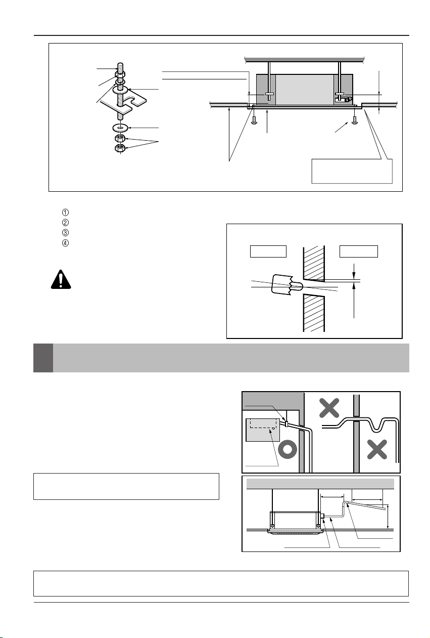
Do not install the product at a place that there
is concern of falling down.
• Otherwise, it may result in personal injury.
Use caution when unpacking and installing.
• Sharp edges may cause injury.
Take the power plug out if
necessary, holding the head
of the plug and do not touch
it with wet hands.
• Otherwise, it may cause a fire
or electrical shock.
Do not use the power cord
near the heating tools.
• Otherwise, it may cause a fire
and electrical shock.
Do not open the suction
inlet of the indoor/outdoor
unit during operation.
• Otherwise, it may electrical
shock and failure.
Do not allow water to run
into electrical parts.
• Otherwise, it may cause the
failure of machine or electrical
shock.
Hold the plug by the head
when taking it out.
• It may cause electric shock
and damage.
Never touch the metal parts
of the unit when removing
the filter.
• They are sharp and may
cause injury.
Do not share the outlet with
other appliances.
• It will cause an electric shock
or a fire due to heat
generation.
Do not use the damaged
power cord.
• Otherwise, it may cause a fire
or electrical shock.
Do not modify or extend the
power cord randomly.
• Otherwise, it may cause a fire
or electrical shock.
Take care so that the power
cord may not be pulled
during operation.
• Otherwise, it may cause a fire
or electrical shock.
Unplug the unit if strange
sounds, smell, or smoke
comes from it.
• Otherwise, it may cause
electrical shock or a fire.
Keep the flames away.
• Otherwise, it may cause a fire.
Do not step on the indoor/outdoor unit and
do not put anything on it.
• It may cause an injury through dropping of the
unit or falling down.
Do not place a heavy object on the power
cord.
• Otherwise, it may cause a fire or electrical
shock.
When the product is submerged into water,
always contact the service center.
• Otherwise, it may cause a fire or electrical
shock.
Take care so that children may not step on
the outdoor unit.
• Otherwise, children may be seriously injured
due to falling down.
■Operation

ENGLISH
Installation Manual 5
Safety Precautions
■Installation
Install the drain hose to ensure that drain
can be securely done.
• Otherwise, it may cause water leakage.
Install the product so that the noise or hot
wind from the outdoor unit may not cause
any damage to the neighbors.
• Otherwise, it may cause dispute with the
neighbors.
Always inspect gas leakage after the
installation and repair of product.
• Otherwise, it may cause the failure of product.
Keep level parallel in installing the product.
• Otherwise, it may cause vibration or water
leakage.
Avoid excessive cooling and perform
ventilation sometimes.
• Otherwise, it may do harm to your health.
Use a soft cloth to clean. Do not use wax,
thinner, or a strong detergent.
• The appearance of the air conditioner may
deteriorate, change color, or develop surface
flaws.
Do not use an appliance for special purposes
such as preserving animals vegetables,
precision machine, or art articles.
• Otherwise, it may damage your properties.
Do not place obstacles around the flow inlet
or outlet.
• Otherwise, it may cause the failure of appliance
or an accident.
■Operation

6Air Conditioner
2. Outdoor unit
• If an awning is built over the unit to prevent
direct sunlight or rain exposure, make sure
that heat radiation from the condenser is not
restricted.
• Ensure that the spaces indicated by arrows
around front, back and side of the unit.
• Do not place animals and plants in the path of
the warm air.
• Take the air conditioner weight into account
and select a place where noise and vibration
are minimum.
• Select a place so that the warm air and noise
from the air conditioner do not disturb
neighbors.
More than
300
More than 700
More than 600
More than
300
Sunroof
Fence or
obstacles
OUTDOOR
Unit
OUTDOOR
Unit
More than
300
Unit : mm
Installation of Indoor, Outdoor Unit
1. Indoor unit
Cassette type
•There should not be any heat source or steam
near the unit.
•There should not be any obstacles to prevent
the air circulation.
•A place where air circulation in the room will
be good.
•A place where drainage can be easily
obtained.
•A place where noise prevention is taken into
consideration.
•Do not install the unit near the door way.
•Ensure the spaces indicated by arrows from
the wall, ceiling, or other obstacles.
•The indoor unit must keep the maintenance
space.
Installation Places
Unit : mm
Ceiling
Ceiling Board Ceiling Board
300 or more
Above 250
1000 or less
1000
or more
500 or
more
500 or
more
300 or less
Floor
Installation of Indoor, Outdoor Unit

The indoor unit installation
Installation Manual 7
ENGLISH
The indoor unit installation
1. Cassette type
Level gauge
Ceiling
Ceiling board
Unit:mm
875(Ceiling opening)
787(Hanging bolt)
684
(Hanging bolt)
671
875(Ceiling opening)
840 Unit size
840 Unit size
•Avoid the following installation location.
1. Such places as restaurants and kitchen where considerable amount of oil steam and flour is generated.
These may cause heat exchange efficiency reduction, or water drops, drain pump mal-function.
In these cases, take the following actions;
•Make sure that ventilation fan is enough to cover all noxious gases from this place.
•Ensure enough distance from the cooking room to install the air conditioner in such a place where it
may not suck oily steam.
2. Avoid installng air conditioner
in such places where
cooking oil or iron powder is
generated.
3. Avoid places where
inflammable gas is generated.
4. Avoid place where noxious gas is
generated.
5. Avoid places near high frequency
generators.
NOTICE
CAUTION :
•This air-conditioner uses a drain
pump.
•Install the unit horizontally using
a level gauge.
•
During the installation, care should be
taken not to damage electric wires.
•Select and mark the position for fixing bolts and piping
hole.
•Decide the position for fixing bolts slightly tilted to the
drain direction after considering the direction of drain
hose.
•Drill the hole for anchor bolt on the wall.
Use the ventilation fan
for smoke-collecting
hood with sufficient
capacity.
Cooking table
Air conditioner
Take enough
distance

8Air Conditioner
The indoor unit installation
Wall
5~7mm
Indoor Outdoor
Set screw of
paper model (4 pieces)
Paper model
for installation
Ceiling board
150mm
Adjust the same height
Ceiling board
Ceiling
Flat washer for M10
(accessory)
Keep the length of the bolt
from the bracket to 40mm
Open the ceiling board
along the outer edge of the
paper model
Flat washer for M10
(accessory)
Hanging bolt
(W3/8 or M10)
Nut
(W3/8 or M10)
Nut
(W3/8 or M10)
Spring washer
(M10)
Air Conditioner body
•The following parts is option.
Hanging Bolt - W 3/8 or M10
Nut - W 3/8 or M10
Spring Washer - M10
Plate Washer - M10
CAUTION:
Tighten the nut and bolt
to prevent unit falling.
•Drill the piping hole on the wall slightly tilted to the
outdoor side using a Ø70 hole-core drill.
•Drain piping must have down-slope (1/50 to
1/100): be sure not to provide up-and-down
slope to prevent reversal flow.
•During drain piping connection, be careful
not to exert extra force on the drain port on
the indoor unit.
•The outside diameter of the drain
connection on the indoor unit is 32mm.
•Be sure to execute heat insulation on the
drain piping.
•Install the drain raising pipes at a right
angle to the indoor unit and no more than
300mm from the unit.
Maintenance
drain port
Upward
routing
not allowed
Pipe clamp
Indoor unit
700 or less
1 -1.5m
300mm or less
Flexible drain hose
Clamp metal(attached) Drain hose(attached)
Drain raising pipe
Piping material: Polyvinyl chloride pipe VP-25
and pipe fittings
Heat insulation material: Polyethylene foam with thickness more than 8 mm.
Indoor Unit Drain Piping

Indoor Unit Drain Piping
Installation Manual 9
ENGLISH
Heat insulation
1. Use the heat insulation material for the refrigerant piping which has an excellent heat-resistance
(over 120°C).
2. Precautions in high humidity
circumstance:
This air conditioner has been tested
according to the "KS Standard Conditions
with Mist" and confirmed that there is not
any default. However, if it is operated for a
long time in high humid atmosphere (dew
point temperature: more than 23°C), water
drops are liable to fall. In this case, add
heat insulation material according to the
following procedure:
•Heat insulation material to be prepared...
Adiabatic glass wool with thickness 10 to
20mm.
•Stick glass wool on all air conditioners that
are located in ceiling atmosphere.
Indoor unit
Thermal insulator
(accessory)
Fastening band
(accessory)
Refrigerant piping
The air conditioner uses a drain pump to drain water.
Use the following procedure to test the drain pump operation:
•Connect the main drain pipe to the exterior and leave
it provisionally until the test comes to an end.
•Feed water to the flexible drain hose and check the
piping for leakage.
•Be sure to check the drain pump for normal
operating and noise when electrical wiring is
complete.
•When the test is complete, connect the flexible drain
hose to the drain port on the indoor unit.
Feed water
Drain Pump
Drain pan
Flexible drain hose
(accessory)
Main
drain pipe
Glue the joint
Drain
port
Drain hose connection
Use the clip (accessory)
Flexible drain hose
Drain test

10 Air Conditioner
Connecting Pipes
Copper
tube
90°Slanted Uneven Rough
Pipe
Reamer
Point down
Flare nut
Copper tube
Bar
Copper pipe
Clamp handle Red arrow mark
Cone
Yoke
Handle
Bar
"A"
Inclined
Inside is shining without scratches
Smooth all round
Even length
all round
Surface
damaged Cracked Uneven
thickness
= Improper flaring =
Connecting Pipes
Preparation of Piping
Main cause of gas leakage is defect in flaring
work. Carry out correct flaring work in the
following procedure.
Cut the pipes and the cable.
•Use the accessory piping kit or the pipes
purchased locally.
•Measure the distance between the indoor
and the outdoor unit.
•Cut the pipes a little longer than measured
distance.
•
Cut the cable 1.5m longer than the pipe
length.
Burrs removal
•Completely remove all burrs from the cut
cross section of pipe/tube.
•
Put the end of the copper tube/pipe to
downward direction as you remove burrs in
order to avoid to let burrs drop in the tubing.
Putting nut on
•Remove flare nuts attached to indoor and
outdoor units, than put them on pipe/tube
having completed burr removal.
(Not possible to put them on after flaring work)
Flaring work
•
Carry out flaring work using dedicated
flaring tool for R-410A as shown below.
Firmly hold copper tube in a bar(or die) as
indicated dimension in the table above.
Check
•Compare the flared work with figure below.
•If flare is noted to be defective, cut off the
flared section and do flaring work again.
Outside diameter "A"
mm inch mm
Ø6.35 1/4 1.1~1.3
Ø9.52 3/8 1.5~1.7
Ø12.7 1/2 1.6~1.8
Ø15.88 5/8 1.6~1.8
Ø19.05 3/4 1.9~2.1

Connecting Pipes
Installation Manual 11
ENGLISH
•Align the center of the piping and sufficiently
tighten the flare nut by hand.
•Finally, tighten the flare nut with torque wrench
until the wrench clicks.
- When tightening the flare nut with torque
wrench, ensure the direction for tightening
follows the arrow on the wrench.
❈When tighten the pipe, hold the haxagonal
body.
mm inch kgf.m
Ø6.35 1/4 1.8~2.5
Ø9.52 3/8 3.4~4.2
Ø12.7 1/2 5.5~6.6
Ø15.88 5/8 6.3~8.2
Ø19.05 3/4 9.9~12.1
Outside diameter Torque
Continuous
Torque
wrench
(250mm)
Torque
wrench
(250mm)
•Align the center of the pipings and sufficiently
tighten the flare nut by hand.
•Tighten the flare nut with a wrench.
•When extending the drain hose at the indoor
unit, install the drain pipe.
Indoor unit tubing Flare nut Pipings
Torque wrench
Indoor unit tubing
Spanner (fixed)
Connection pipe
Flare nut
mm inch kg.m
Ø6.35 1/4 1.8~2.5
Ø9.52 3/8 3.4~4.2
Ø12.7 1/2 5.5~6.6
Ø15.88 5/8 6.6~8.2
Ø19.05 3/4 9.9~12.1
Outside diameter Torque
Vinyl tape(narrow)
Adhesive
Drain pipe
Indoor unit drain hose
Connecting the pipings to the indoor unit and drain hose to drain pipe
Connecting the pipes to the Outdoor unit

12 Air Conditioner
Remote Controller Installation
12V SIG GND
Red
Yellow
Black
Remote Controller
Cable
Guide slot
Fixate the remote
controller cable
to the guide slot.
Use the screws
for fixate the unit
firmly on the wall.
Installation board
<Front side of
installation board>
<Rear side of
installation board>
Top
Bottom
Wall
Side
Wall
Side
Wall
Side
Wall
Side
Wall
Side
1. Connect the remote controller cable to the
wired remote controller installation board as
shown in the right picture.
2. After fixing the cable to the guide slot,
attach the wired remote controller
installation board at the desired location.
•Before fixing the remote controller cable to the
guide slot, remove any clogged part of the case
in the direction to install before the installation.
3. After locating the wired remote controller
installation board at the desired location,
screw the unit firmly. (When there is a buried
box, install the wired remote controller
board to fit the buried box.)
•Use the screws provided.
4. After fixing the top part of the remote
controller to the installation board as shown
in beside picture, press the bottom part to
assemble the controller to it’s board.
When disassembling the remote controller from
the installation board, use the driver as shown in
the right picture and insert it into the hole with the
arrow. And when you pull the driver in the front
direction, the remote controller will be separated.
12V Red wire
SIG Yellow wire
GND Black wire
❊The remote controller cable is connected as factory default.

Remote Controller Installation
Installation Manual 13
ENGLISH
5. Use the connecting cable to connect the indoor unit and the remote controller.
6. When the distance between the wired remote controller and the indoor unit is 10m and
above, use the extension cable.
When installing the wired remote controller, do not bury it in the wall.
(It can cause damage in the temperature sensor.)
Do not install the cable to be 50m or above.
(It can cause communication error.)
•When installing the extension cable, check the connecting direction of the connector of the remote
controller side and the product side for correct installation.
•If you install the extension cable in the opposite direction, the connector will not be connected.
•Specification of extension cable: 2547 1007 22# 2 core 3 shield 5 or above.
Check whether the connector
is connected correctly.
Connecting cable
Indoor
unit side

14 Air Conditioner
The outdoor unit installation
* Make sure the rubber bushes are
Properly used in knock-out holes after
connecting main Power cable
Connecting cable terminal
Power cord terminal
Cord clamp
Cord clamp
•Remove the side panel for wiring connection.
•Use the cord clamp to fix the cord.
•Earthing work
- Case 1 :Terminal block of Outdoor Unit have mark.
•Connect the cable of diameter 1.6mm2or more to the earthing terminal provided in
the control box and do earthing.
- Case 2 :Terminal block of Outdoor Unit don't have mark.
•Connect the cable of diameter 1.6mm2or more, to the panel of control box, marked
as and fasten with earth screw.
Please check !!
Connecting the cable to Outdoor Unit
CAUTION:
•The circuit diagram is not subject to change without notice.
•Be sure to connect wires according to the wiring diagram.
•Connect the wires firmly, so that not to be pulled out easily.
•Connect the wires according to color codes by referring the wiring diagram.

The outdoor unit installation
Installation Manual 15
ENGLISH
•The installation piping is connectable in four
directions.(refer to figure 1)
•When connecting in a downward direction, knock
out the knockout hole of the base pan.
(refer to figure 2)
Preventing foreign objects from entering
(refer to figure 3)
•Plug the pipe through-holes with putty or
insulation material(procured locally)to stop up all
gaps,as shown in the figure 3.
•Insects or small animals entering the outdoor unit
may cause a short circuit in the electrical box.
Knock-out Base pan
Forward Sideways
Backward
Downward
Gas side piping
(Bigger Dia.)
Liquid side piping
(Smaller Dia.)
Drain hose
Connecting wire
Connection pipe
<Figure 3>
<Figure 1>
Putty or insulating material
(produced locally)
<Figure 2>

16 Air Conditioner
The outdoor unit installation
Forming the piping
Form the piping by wrapping the
connecting portion of the indoor
unit with insulation material and
secure it with two kinds of vinyl
tape.
•If you want to connect an additional drain
hose, the end of the drain outlet should be
routed above the ground. Secure the drain
hose appropriately.
In cases where the outdoor unit is
installed below the indoor unit
perform the following.
1. Tape the piping, drain hose and connecting
cable from down to up.
2. Secure the tapped piping along the exterior
wall using saddle or equivalent.
In cases where the Outdoor unit is
installed above the Indoor unit
perform the following.
1. Tape the piping and connecting cable from
down to up.
2. Secure the taped piping along the exterior
wall. Form a trap to prevent water entering
the room.
3. Fix the piping onto the wall by saddle or
equivalent.
Trap
Plastic
band
Seal a small
opening around
the pipings with
gum type sealer.
TrapTrap
Seal a small opening
around the pipings
with gum type sealer.
Seal a small opening
around the pipings
with gum type sealant.
OUTDOOR
UNIT
OUTDOOR
UNIT
OUTDOOR
UNIT
•Trap is required to prevent water from entering
into electrical parts.
Taping
Drain hose
Pipings
Connecting
cable
Power supply
cord
Plastic
band
Plastic
band
Seal a small
opening around
the pipings with
gum type sealer.
Seal a small
opening around
the pipings with
gum type sealant.
Trap
Seal a small opening
around the pipings
with gum type sealer.
OUTDOOR
UNIT
OUTDOOR
UNIT
OUTDOOR
UNIT

Leakage test and Evacuation
Installation Manual 17
ENGLISH
Leakage test and Evacuation
Air and moisture remaining in the refrigerant system have undesirable effects as indicated below.
1. Pressure in the system rises.
2. Operating current rises.
3. Cooling(or heating) efficiency drops.
4. Moisture in the refrigerant circuit may freeze and block capillary tubing.
5. Water may lead to corrosion of parts in the refrigeration system.
Therefore, the indoor/outdoor unit and connecting tube must be checked for leak tight, and
vacuumed to remove incondensible gas and moisture in the system.
•Check that each tube(both liquid and gas side tubes) between the indoor and outdoor units have been
properly connected and all wiring for the test run has been completed. Remove the service valve caps
from both the gas and the liquid side on the outdoor unit. Check that both the liquid and the gas side
service valves on the outdoor unit are kept closed at this stage.
•Connect the manifold valve(with pressure gauges)
and dry nitrogen gas cylinder to this service port
with charge hoses.
CAUTION:
Be sure to use a
manifold valve for leakage test.
If it is not available, use a stop valve for
this purpose. The "Hi" knob of the
manifold valve must always be kept
close.
•Pressurize the system to no more than 3.0
Mpa with dry nitrogen gas and close the
cylinder valve when the gauge reading
reached 3.0 Mpa Next, test for leaks with
liquid soap.
CAUTION:
To avoid nitrogen
entering the refrigerant system in a
liquid state, the top of the cylinder must be
higher than its bottom when you pressurize
the system. Usually, the cylinder is used in
a vertical standing position.
1. Do a leakage test of all joints of the
tubing(both indoor and outdoor) and both gas
and liquid side service valves.
Bubbles indicate a leak. Be sure to wipe off
the soap with a clean cloth.
2. After the system is found to be free of leaks,
relieve the nitrogen pressure by loosening the
charge hose connector at the nitrogen
cylinder. When the system pressure is
reduced to normal, disconnect the hose from
the cylinder.
Preparation
Leakage test
Charge hose
Indoor unit
Outdoor unit
Manifold valve
Pressure
gauge
Nitrogen gas
cylinder(in vertical
standing position)
Lo Hi

18 Air Conditioner
Leakage test and Evacuation
1. Connect the charge hose end described in the
preceding steps to the vacuum pump to evacuate
the tubing and indoor unit.
Confirm the "Lo and Hi" knob of the manifold valve
is open. Then, run the vacuum pump.
The operation time for evacuation varies with tubing
length and capacity of the pump. The following table
shows the time required for evacuation.
2. When the desired vacuum is reached, close the "Lo
and Hi" knob of the manifold valve and stop the
vacuum pump.
Finishing the job
1. With a service valve wrench, turn the valve stem of
liquid side valve counter-clockwise to fully open the
valve.
2. Turn the valve stem of gas side valve counter-
clockwise to fully open the valve.
3. Loosen the charge hose connected to the gas side
service port slightly to release the pressure, then
remove the hose.
4. Replace the flare nut and its bonnet on the gas side
service port and fasten the flare nut securely with
an adjustable wrench. This process is very
important to prevent leakage from the system.
5. Replace the valve caps at both gas and liquid side
service valves and fasten them tight.
This completes air purging with a vacuum pump.
The air conditioner is now ready to test run.
Indoor unit
Outdoor unit
Manifold valve
Vacuum pump
Open Open
Pressure
gauge
Lo Hi
Evacuation
Required time for evacuation when 30 gal/h
vacuum pump is used
30 min. or more 60 min. or more
0.5 torr or less
If tubing length is less
than 10 m(33 ft)
If tubing length is longer
than 10 m(33 ft)

Installation to Decorative Panel
Installation Manual 19
ENGLISH
Installation to Decorative Panel
The decorative panel has its installation direction.
Before installing the decorative panel, always remove the paper template.
1. Remove the packing and take out air inlet
grille from front panel.
2. Remove the Corner covers of the panel.
3. Fit the panel on the unit by inserting
hooks as shown in picture.
4. Insert two screws on diagonal corners of
panel. Do not tighten the bolts completely.
(The fixing screws are included in the
indoor unit box.)
Check the alignment of panel with the
ceiling. Height can be adjusted using
hanging bolts as shown in picture. Insert
the other two screws and tighten all
screws completely.
Front grille
Coner cover
Hook clip
Hook

20 Air Conditioner
Installation to Decorative Panel
5. Fit the corner covers.
6. Open two screws of control panel cover.
7. Connect one display connector and two
vane control connectors of front panel to
indoor unit PCB.
The position marking on PCB is as:
Display connector : CN-DISPLAY
Vane control connector: CN-VANE 1,2
8. Close the cover for control box.
9. Install the air inlet grille and Filter on the
panel.
Screw
CN-VANE 1,2 CN-DISPLAY
CAUTION:
Install certainly the decorative panel.
Cool air leakage causes sweating. Water drops fall.
Air conditioner
unit
Ceiling
board
Decorative panel Decorative
panel
Fit the insulator (this part) and
be careful for cool air leakage
Good example
Air
Cool air leakage
(no good)
Bad example
Ceiling
board
Air conditioner unit
Flexible drain hose
Other manuals for UU21WH
1
This manual suits for next models
1
Table of contents
Other LG Air Conditioner manuals
Popular Air Conditioner manuals by other brands

TemperZone
TemperZone OPA 2000RKTM01 Installation & maintenance

York
York PREDATOR MagnaDRY DR120 installation manual

Mitsubishi
Mitsubishi Mr.Slim MSZ-GE12NA operating instructions

Haier
Haier H2SM-(9+12)HV03/R2 Service manual

Pioneer
Pioneer YN009GMFI22RPD installation manual

Technibel
Technibel MCAF184MR5IAA operating instructions