LG 55VM5J User manual

2
ENGLISH
TABLE OF CONTENTS
BASIC .............................................3
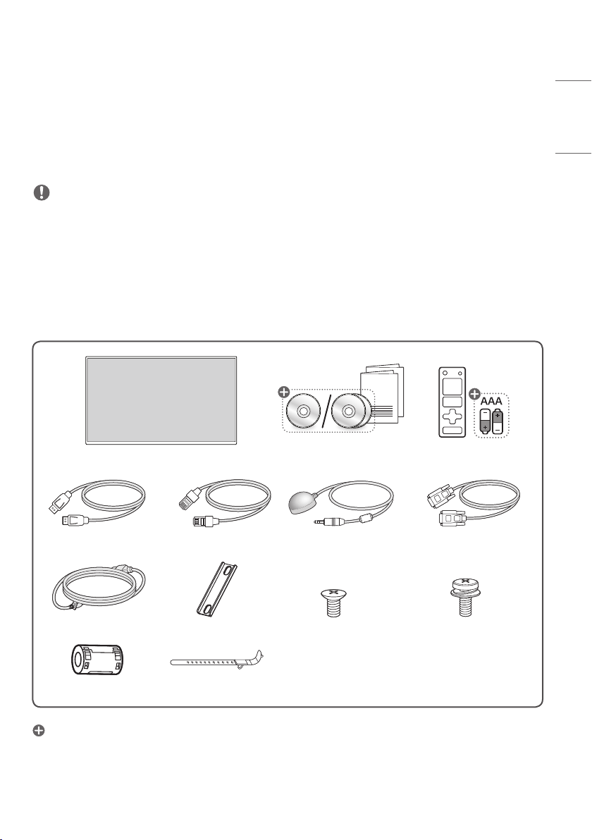
- Checking the Accessories ............................................3
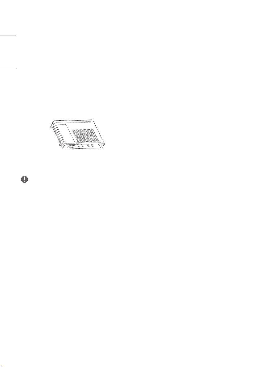
- Checking the Optional Accessories.........................4
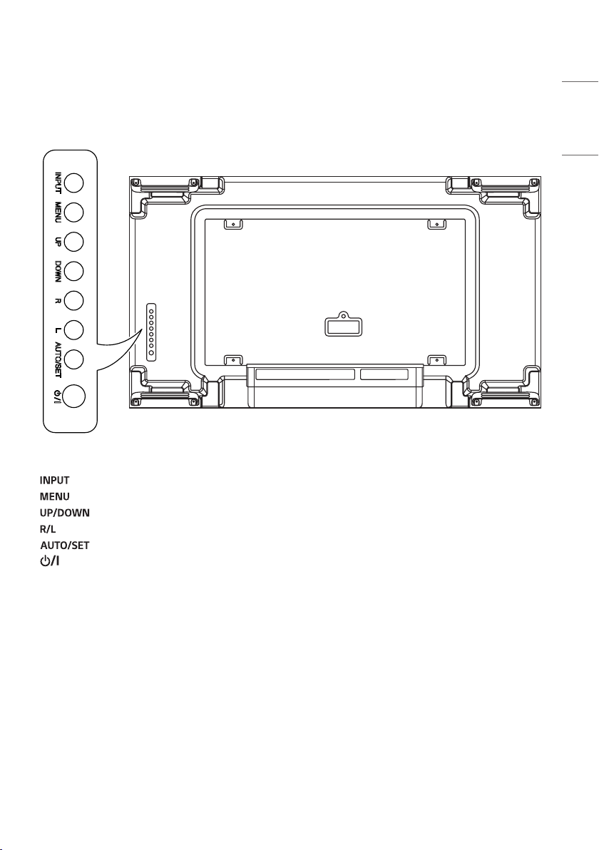
- Learning the Buttons......................................................5
GETTING READY ...........................6
- Storage Method for Panel Protection...................6
- Connecting the IR Sensors..........................................8
- Kensington Lock Device ................................................9
CHECKING BEFORE
INSTALLATION ........................... 10
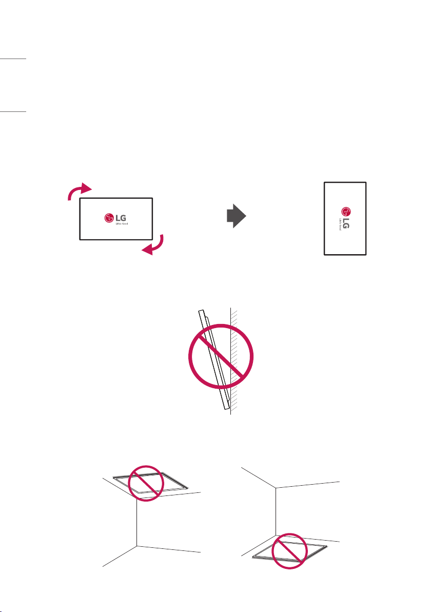
- Installation Orientation ..............................................10
- Installation Location.....................................................11
- Wall Mount Holder .......................................................12
- Safety and Precaution Guide for Installation ..14
- Tiling Displays ..................................................................15
PRECAUTIONS FOR USE............ 18
- Dust.......................................................................................18
- Afterimage ........................................................................18
PRODUCT SPECIFICATIONS...... 20
LICENCE...................................... 23

3
ENGLISH
This product is not intended for household use.
BASIC
NOTE
•The accessories provided with your product may vary depending on the model or region.
•Product specifications or contents in this manual may be changed without prior notice due to upgrade of product
functions.
•SuperSign Software & Manual
- Visit http://partner.lge.com to download the latest SuperSign software and manual.
Checking the Accessories
x 4 x 8 x 4
(M4 x L6) (M6 x L14)
x 2
Depending on country

4
ENGLISH
How to use the ferrite core
1 Use the ferrite core to reduce the electromagnetic interference in the power cable. Wind the power cable on the
ferrite core once.
2 Place the ferrite core close to the monitor.
Checking the Optional Accessories
In order to improve product performance, optional accessories are subject to change without prior notice.
The illustrations in this manual may differ from the actual product and its accessories.
Refer to the product manual for the components of the optional accessories.
KT-OPSF
NOTE
•Before you attach the OPS kit, connect the cable to the port.

5
ENGLISH
Learning the Buttons
The illustrations may differ depending on the model.
•: Change the input signal.
•: Accesses the main menus, or saves your input and exits the menus.
•: Adjust the up and down.
•: Moves left and right.
•: Displays the current signal and mode.
•: Turns the power on or off.

6
ENGLISH
GETTING READY
Storage Method for Panel Protection
Correct Method
1 If the product needs to be set upright, hold both sides of the product, and tilt backward carefully for. Do not let the
panel to touch the floor.
Panel
2 When laying down the product, lay a cushion on a flat floor. Put the product on it with the panel of the product
facing down.
Cushion
Panel
3 If there is not a cushion available, ensure the floor is clean and then lay the product down carefully with the panel
facing either upward or downward. At this time, be careful for objects not to fall on the panel.
Panel

7
ENGLISH
Incorrect Method
1 If the product is tilted onto the bezel, the bottom of the panel may be damaged.
Panel
2 If the product is tilted toward the corner of the panel, the bottom of the panel may be damaged.
Panel

8
ENGLISH
Connecting the IR Sensors
This allows a remote control sensor to be placed in a custom location.
Then that display can control other displays via an RS-232C cable.

9
ENGLISH
Kensington Lock Device
(This feature applies only to some models.)
The Kensington lock device connector is located on the back of the monitor. For more information on installation and
use, refer to the user manual provided with the locking device.
Connect the Kensington security system cable between the monitor and a table.
NOTE
•The Kensington lock device is an optional specification.
•This is a general illustration of installation and may look different from the product held by the customer.

10
ENGLISH
CHECKING BEFORE INSTALLATION
We are not responsible for product damage caused by failure to follow the guide.
Installation Orientation
Using Vertically
When installing vertically, rotate the monitor 90 degrees clockwise while facing the front of the screen.
Tilt Angle
40 mm
15˚
Ceiling, Floor Orientation

11
ENGLISH
Installation Location
We are not responsible for product damage caused by failure to follow the guide.
Indoor
Installing on a Wall
A
B
B
B
B
B
B
BBA
A : 200mm or more
B : 100mm or more
•The warranty will not cover any damage
caused by using the product in direct sunlight
on the front panel.
Installing on a Recessed Wall
A
B
B
B
B
B
B
BBA
A : 200mm or more
B : 100mm or more
•The warranty will not cover any damage
caused by using the product in direct sunlight
on the front panel.
Outdoor
Outdoor Enclosed

12
ENGLISH
Wall Mount Holder
To install the monitor on a wall, attach a wall mount holder (optional) to the back of the monitor.
Take caution, and ensure that the wall mount holder (optional) is securely fixed to the monitor and to the wall.
The VESA dimensions of the wall mount by model are as follows.
A
B
Model VESA Dimensions
(A x B) (mm)
Standard
Dimensions
Length (Maximum)
(mm) Quantity
55VH7J
55VM5J 600x400 M6 16 4
CAUTION
•Disconnect the power cord first, and then move or install the monitor. Otherwise, it may result in electric shock.
•If the monitor is installed on a ceiling or inclined wall, it may fall and result in injury.
•Damage to the monitor by tightening the screws too tightly may void your warranty.
•Use screws and wall mount plates conforming to VESA standards. Breakage or personal injury due to use or misuse
of inappropriate components is not covered by the warranty of this product.
NOTE
•Using screws longer than the indicated depth may damage the inside of the product. Be sure to use the proper length.
•For more information on installation, please refer to the user manual for the wall mount.

13
ENGLISH
Securing the monitor to a wall (optional)
(Depending on model)
1 Insert and tighten the eyebolts, or brackets and bolts on the back of the monitor.
- If there are already bolts inserted in the eyebolts’ position, remove the other bolts first.
2 Mount the wall brackets with the bolts to the wall. Match the location of the wall bracket and the eyebolts on the
rear of the monitor.
3 Connect the eyebolts and wall brackets tightly with a sturdy cord.
Make sure the securing cord is horizontal with the flat surface.
WARNING
•If the monitor is not positioned in a sufficiently stable location, there is a danger that it will fall. Many injuries,
particularly to children, can be avoided by taking simple precautions such as:
- Only using furniture that can safely support the monitor.
- Ensuring the monitor is not overhanging the edge of the supporting furniture.
- Not placing the monitor on tall furniture (for example, cupboards or bookcases) without anchoring both the
furniture and the monitor to a suitable support.
- Not placing cloth or other materials between the monitor and supporting furniture.
- Educating children about the dangers of climbing on furniture to reach the monitor or its controls.
CAUTION
•Make sure that children do not climb on or hang from the monitor.
NOTE
•Use a platform or cabinet that is large and strong enough to support the monitor securely.
•Brackets, bolts, and cords are sold separately. You can obtain additional accessories from your local retail store.
•The illustration shows a general example of installation and may look different from the actual product.

14
ENGLISH
Safety and Precaution Guide for Installation
During installation, ensure any conductive materials (metals, etc.) do not enter through the gaps or vent holes between
the panel and the back cover.
- Covering the back of the product with a cloth may prevent foreign substances from entering the product and causing
malfunction.
- Make sure to remove the cloth after the installation is complete.

15
ENGLISH
Tiling Displays
How to Mount the Set
Example of 2x2 Tiling
Using the screws for attaching the VESA wall mount, mount the set to the wall mount plate or the wall.
Screws for attaching the VESA wall
mount (M6)
(Unit: mm)
600
400

16
ENGLISH
How to Join Sets
1 Install the additional sets using the VESA wall mounting screws by using the same method mentioned before.
(M4 x L6)
2 Complete the 2x2 tiling. You can use various options of tiling including 3x3 by using the same method.
Completeness of the Set (2x2 tiling complete)
CAUTION
•Make sure to level the sets before tightening the tiling guide; doing so when the set axis is rotated may cause
damage to the panel.

17
ENGLISH
NOTE
•The load applied to each set should be supported by the wall mount plate or the wall using a VESA wall mount
(600x400).
•The load applied to each set should be supported by the wall mount plate using a VESA wall mount. (Each set must
be firmly mounted to the wall mount plate or the wall.)
•You may mount the set without using the tiling guide; this does not affect the performance of the device.
•The screws are enclosed with the other components in the box, including the tiling guides.

18
ENGLISH
PRECAUTIONS FOR USE
Dust
The warranty will not cover any damage caused by using the product in an excessively dusty environment.
Afterimage
•After-image appears when the product is turned off.
- Pixels may be damaged rapidly if a still image is displayed on the screen for a long period of time. Use the screen-
saver function.
- Switching from a screen with high differences in luminance (black and white or grey) to a darker screen may cause
an afterimage. This is normal due to the display characteristics of this product.
•When the LCD screen is in a still pattern for extended periods of use, a slight voltage difference may occur between
the electrodes that operate the liquid crystal (LC). The voltage difference between the electrodes increases over time
and tends to keep the liquid crystal aligned in one direction. At this time, the previous image remains, which is called
an afterimage.
•Afterimages do not occur when continuously changing images are used but take place when a certain screen is fixed
for a long time. The following are operational recommendations for reducing the occurrence of afterimages when
using a fixed screen. The maximum recommended time for switching the screen is 12 hours. Shorter cycles are better
for preventing afterimages.

19
ENGLISH
•Recommended Usage Condition
1 Change the background colour and text colour at equal intervals.
- Afterimages occur less when the colours to be changed are complementary to one another.
A
A
AA
A
A
ITO or MoTi Pixel Layer
2 Switch the screen at equal time intervals.
- Take caution, and ensure that text or images from before the screen change are not left in the same location after
the screen change.

20
ENGLISH
PRODUCT SPECIFICATIONS
Without prior notice, all product information and specifications contained in this manual are subject to change to
improve the performance of the product.
55VH7J
Input/Output Ports
Resolution
Recommended Resolution 1920x1080 @ 60Hz
Max Resolution
HDMI1 / HDMI2 / DisplayPort: 3840x2160 @ 60Hz
OPS: 3840x2160 @ 30Hz
DVI-D: 1920x1080 @ 60Hz
Power Voltage 100-240V~50/60Hz 2.7A
Environmental
Conditions
Operating Temperature
Operating Humidity
0°C to40°C
10% to 80% (Condition for preventing condensation)
Storage Temperature
Storage Humidity
-20°C to60°C
5% to 85% (Condition for preventing condensation)
* Product box packaging storage conditions
Power
Consumption
On Mode 210W(Typ.)
Sleep Mode / Standby Mode ≤0.5W
55VM5J
Input/Output Ports
Resolution
Recommended Resolution 1920x1080 @ 60Hz
Max Resolution
HDMI1 / HDMI2 / DisplayPort: 3840x2160 @ 60Hz
OPS: 3840x2160 @ 30Hz
DVI-D: 1920x1080 @ 60Hz
Power Voltage 100-240V~50/60Hz 2.7A
Environmental
Conditions
Operating Temperature
Operating Humidity
0°C to40°C
10% to 80% (Condition for preventing condensation)
Storage Temperature
Storage Humidity
-20°C to60°C
5% to 85% (Condition for preventing condensation)
* Product box packaging storage conditions
Power
Consumption
On Mode 160W(Typ.)
Sleep Mode / Standby Mode ≤0.5W
Model Name Size (Width x Height x Thickness) (mm) Weight (kg)
55VH7J
55VM5J 1,212.2x 683.0x 86.9 18.8
This manual suits for next models
3
Table of contents
Other LG Digital Signage manuals
Popular Digital Signage manuals by other brands

Visel Italiana
Visel Italiana NEXTAB QS-NEXTAB10 user guide

EVERI
EVERI Enrollment Kiosk Quick reference guide

All Traffic Solutions
All Traffic Solutions InstAlert 18 quick start guide

FUELCLOUD
FUELCLOUD Kiosk Lite installation manual

WebDT
WebDT SA1000 quick start guide

Meridian
Meridian PMK quick start guide