LG DLEX7200 series User manual

DLEX7200* DLGX7201*MODEL :
Any reproduction, duplication, distribution (including by way of email, facsimile or other electronic means),
publication, modication, copying or transmission of this Service Manual is STRICTLY PROHIBITED
unless you have obtained the prior written consent of the LG Electronics entity from which you received this
Service Manual. The material covered by this prohibition includes, without limitation, any text, graphics or
logos in this Service Manual.
Copyright © 2016 - 2017 LG Electronics Inc. All rights reserved. Only training and service purposes.
CONFIDENTIAL

2
6QCXQKFRGTUQPCNKPLWT[FKUEQPPGEVRQYGTDGHQTGUGTXKEKPIVJKURTQFWEV+HGNGEVTKECNRQYGTKUTGSWKTGFHQTFKCIPQUKUQTVGUV
RWTRQUGUFKUEQPPGEVVJGRQYGTKOOGFKCVGN[CHVGTRGTHQTOKPIVJGPGEGUUCT[EJGEMU6QTGFWEGVJGTKUMQHRGTUQPCNKPLWT[
CFJGTGVQCNNKPFWUVT[TGEQOOGPFGFUCHGV[RTQEGFWTGUKPENWFKPIVJGWUGQHNQPIUNGGXGFINQXGUCPFUCHGV[INCUUGU
(CKNWTGVQHQNNQYCNNQHVJGUCHGV[YCTPKPIUKPVJKUOCPWCNEQWNFTGUWNVKPRTQRGTV[FCOCIGRGTUQPCNKPLWT[QTFGCVJ$GECTGHWN
YJGPQRGPKPICPFENQUKPIVJGFQQT(KPIGTUCPFJCPFUECPIGVECWIJVKPVJGFQQTCPFECWUGKPLWT[KHVJGFQQTFTQRUHQTYCTF
WPGZRGEVGFN[&QPQVRNCEGJGCX[KVGOUQPQTNGCPCICKPUVVJGVQRQHVJGFQQTYJGPKVKUQRGP&QPQVCVVGORVVQRWNNVJGJCORGT
FQQTQRGPOQTGVJCPFGITGGU6JG&T[GTEQWNFVKRHQTYCTFECWUKPIKPLWT[QTFCOCIG
9#40+0)
9*#661&1+(;175/'..)#5
+/2146#065#('6;016+%'
4'%100'%6#..)4170&+0)&'8+%'5
+/2146#06
&QPQVVT[VQNKIJVCOCVEJQTEKICTGVVGQTVWTPQP
CP[ICUQTGNGEVTKECNCRRNKCPEG
&QPQVVQWEJCP[GNGEVTKECNUYKVEJGU&QPQVWUG
CP[RJQPGKP[QWTDWKNFKPI
%NGCTVJGTQQODWKNFKPIQTCTGCQHCNNQEEWRCPVU
+OOGFKCVGN[ECNN[QWTICUUWRRNKGTHTQOC
PGKIJDQTŏURJQPG(QNNQYVJGICUUWRRNKGTŏU
KPUVTWEVKQPUECTGHWNN[
+H[QWECPPQVTGCEJ[QWTICUUWRRNKGTECNNVJGHKTG
FGRCTVOGPV

3
481#Wdj#Rq#1111111111111111111111111111111111111111111111111111111111111111111111111111111111111111111111111111111111111111111111111111111111111111111111111#93
491
49041
44
45
48
49
4:
4:
4;
4<
53
53
54
55
56
57
5:
5;
5<
63
64
65
66
67
69
85
8;
9:
9:
9;
9<
:3
:4
4905041
4905051
4906041
4906051
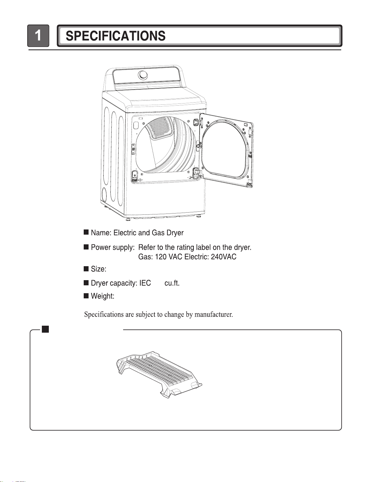
1. SPECTIFICATIONS ................................................................................................................ 4
2. FEATURES AND BENEFITS ...................................................................................................6
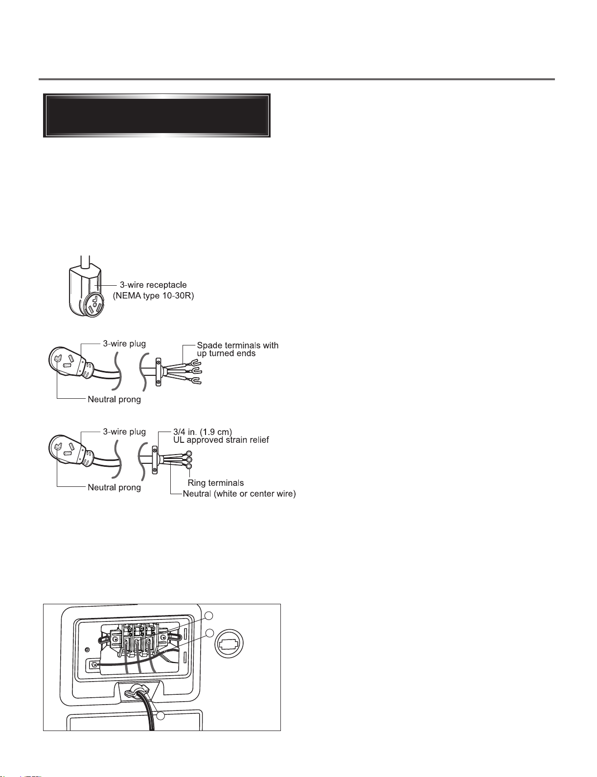
3. INSTALLATION INSTRUCTIONS ............................................................................................6
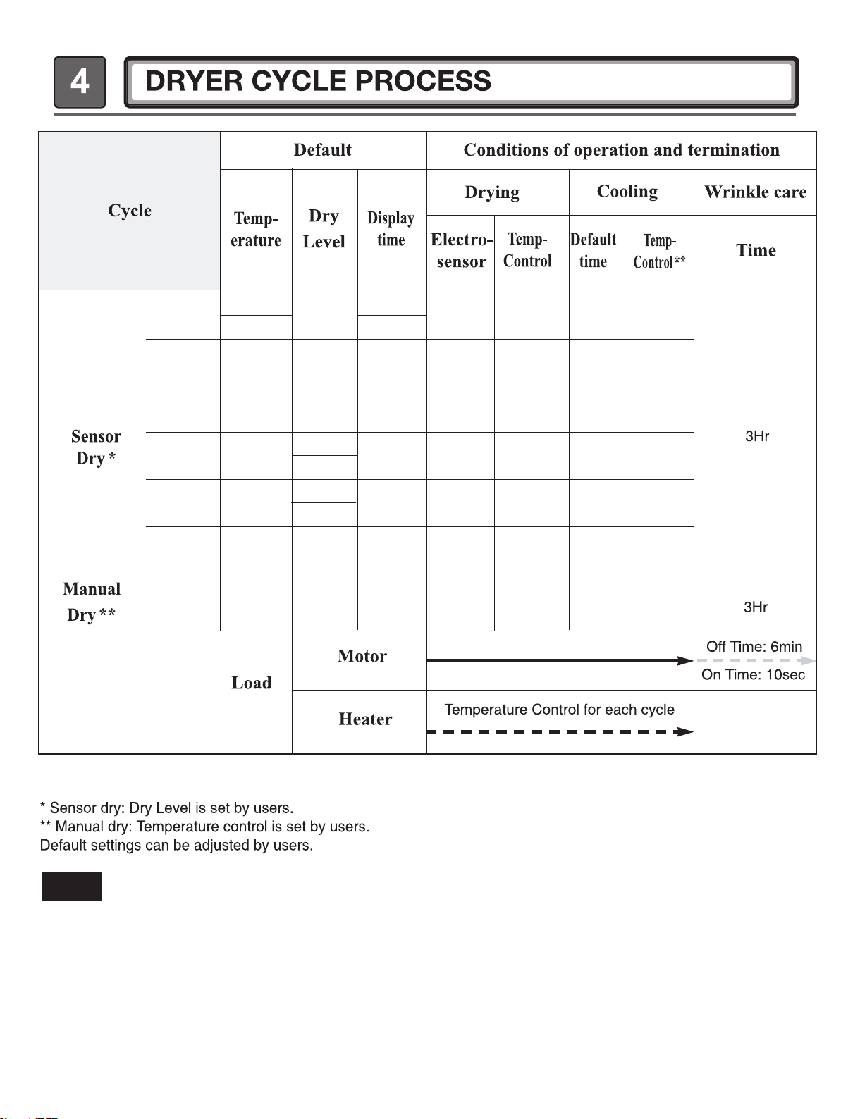
4. DRYER CYCLE PROCESS ...................................................................................................10
5. COMPONENT TESTING INFORMAITON .............................................................................11
6. MOTOR DIAGRAM AND SCHEMATIC ..................................................................................14
7. WIRING DIAGRAM ................................................................................................................15
8. FLOW SENSORFUNCTION .................................................................................................17
9. DIAGNOSTIC TEST ...............................................................................................................20
10-1. TEST 1 120 VAC ELECTRICAL SUPPLY ....................................................................21
10-2. TEST 2 THERMOSTOR TEST - MEASURE WITH POWER OFF ...............................24
10-3. TEST 3 MOTOR TEST..................................................................................................25
10-4. TEST 4 MOISTURE SENSOR ......................................................................................26
10-5. TEST 5 DOOR SWITCH TEST .....................................................................................27
10-6. TEST 6 HEATER SWITCH TEST - ELECTRIC TYPE ..................................................28
10-7. TEST 7 GAS VALVE TEST - GAS TYPE......................................................................29
10. CHANGE GAS SETTING (NATURAL GAS, PROPANE GAS) ............................................30
11. DISASSEMBLY INSTRUCTIONS ........................................................................................32
12. REVERSING THE DOOR ....................................................................................................50
12. FASTENER CHART - SIZE AND POSITIONS ....................................................................57
12-1. DOOR..........................................................................................................................57
12-2. CABINET COVER .......................................................................................................58
13. EXPLODED VIEW ................................................................................................................59
13-1. CONTROL PANEL AND PLATE ASSEMBLY.............................................................59
13-2-1. CABINET AND DOOR ASSEMBLY : ELECTRIC TYPE..........................................60
13-2-2. CABINET AND DOOR ASSEMBLY : GAS TYPE ....................................................61
13-3-1. DRUM AND MOTOR ASSEMBLY : ELECTRIC TYPE ............................................62
13-3-2. DRUM AND MOTOR ASSEMBLY : GAS TYPE ......................................................63
Copyright © 2016 - 2017 LG Electronics Inc. All
rights reserved. Only training and service purposes.

4
See page 6 of this manual for usage instruction.
Dryer rack (1 each)
ACCESSORIES
Optional accessory
Y^GGGY_U`GG[\UZGOP
XZ]UZGnGGaGX\]UZGGO^WU`GP
lGGaGX\YU_GO]`UZGP
^UZ

5
DLE7200*E DLG7201*E
9.0 cu.ft.
Inlet Valve
Control Lock
14W (1.2A) DC 12V
12
7
3
27 X 28.9 X 45.3 (inch)
29.8 X 31.3 X 47.24 (inch)
Gas dryer : 139.8 Electric dryer : 136.3
13

6

7
.
If this type is available at your home. you will be
connecting to a fused disconnect or circuit breaker
box
If this type is available at your home. you will be
connecting to a fused disconnect or circuit breaker
box
3-wire direct
4-wire direct
5"
(12.7 cm)
1"
(2.5 cm)
5"
(12.7 cm)
3-1 Connecting Electric Dryers

8
$
%
&
vGYa 9KTG%QPPGEVKQPYKVJ
C2QYGT5WRRN[%QTF
OI\RXUORFDOFRGHVRURUGLQDQFHVSHUPLWWKH
FRQQHFWLRQRIDIUDPHJURXQGLQJFRQGXFWRUWRWKH
QHXWUDOZLUHXVHWKHVHLQVWUXFWLRQV,I\RXUORFDO
FRGHVRURUGLQDQFHVGRQRWDOORZWKHFRQQHFWLRQRI
DIUDPHJURXQGLQJFRQGXFWRUWRWKHQHXWUDOZLUH
XVHWKHLQVWUXFWLRQVXQGHU5GEVKQP1RVKQPCN
YKTGEQPPGEVKQP
&RQQHFWWKHQHXWUDOZKLWHRUFHQWHUZLUH%WR
WKHFHQWHUVLOYHUFRORUHGVFUHZ$DQGWLJKWHQ
VHFXUHO\
&RQQHFWWKHRWKHUWZRSRZHUFRUGZLUHVUHGDQG
EODFNWRWKHOHIWDQGULJKWWHUPLQDOEORFNVFUHZV
DQGWLJKWHQVHFXUHO\
7LJKWHQWKHVWUDLQUHOLHIVFUHZV&VHFXUHO\

9
3-2 Connecting the gas supply

10
The Energy Saver option is turned on by default in the Cotton/Normal cycle.
Turn off the Energy Saver option for a faster Normal cycle which begins with heated drying.
To turn the Energy Saver default off, press and hold the Wrinkle Care button for three seconds.
ON or OFF appears in the display.
NOTE
67($00,'+,*+
2))
PLQ
6DWXUDWLRQ
Ȕ
PLQ
Ȕ
)5(6+ $GMXVWDEOH$GMXVWDEOH ȕȕ
67($0
+,*+
9HU\
PLQ6DWXUDWLRQ
Ȕ
PLQ
Ȕ
6$1,7$5<'U\ȕ ȕ
+($9<
+,*+
1RUPDO
PLQ6DWXUDWLRQ
Ȕ
PLQ
Ȕ
'87<$GMXVWDEOH ȕȕ
1250$/ 0(',80
1RUPDO(OHF
6DWXUDWLRQ
Ȕ
PLQ
Ȕ
$GMXVWDEOH*DV ȕȕ
3(5035(66/2:
1RUPDO
PLQ6DWXUDWLRQ
Ȕ
PLQ
Ȕ
$GMXVWDEOHȕ ȕ
'(/,&$7(6 /2:
1RUPDO
PLQ6DWXUDWLRQ
Ȕ
PLQ
Ȕ
$GMXVWDEOHȕ ȕ
$,5'5< 12+($7 2))
PLQ
6DWXUDWLRQ12 PLQȔ
$GMXVWDEOH+($7(5ȕ

11
Auto reset -31°F (-35°C)
Same shape as outlet thermostat.
4. LED Lamp Schematic: If the lamp is turned on
by connecting is normal.
It is not
measured by
multimeter
because V is
3.2V
th
Measure resistance of the
following terminal
1) Door open
Terminal: COM - NC (1-3)
Terminal: COM - NO (1-2)
2) Door closed
Terminal: COM - NC (1-3)
Terminal: COM - NO (1-2)

12

13
Ω
Ω
Electric type
Electric type
15. Inlet. valve
16. Generator
Measure resistance of the
following terminal
①Terminal: 1-2
②Terminal: 1-2
①Resistance value: 12.96Ω
②Resistance value: 12.96Ω
Following terminal
Left picture
-.plate

14
Ω
Ω
Ω
Ω
When checking Component, be sure to turn Power off, then do voltage discharge sufficiently.
m

15
Only Steam Model
Only Steam Model

16
Only Steam Model
Only Steam Model

17

18
Installation Test (Duct Check)
Once you have completed the installation of the
dryer, use this test to make sure the condition of the
exhaust system is adequate for proper operation of
the dryer. This test should be performed to alert you
to any serious problems in the exhaust system of
your home.
•Your dryer features Flow Sense™, an innovative
sensing system that automatically detects
blockages and restrictions in dryer ductwork.
Keeping ductwork clean of lint buildup and free of
restrictions allows clothes to dry faster and reduces
energy use.
NOTE
The dryer should be cool before starting this test.
If the dryer was warmed up during installation, run
the AIR DRY cycle for a few minutes to reduce
the interior temperature.
To activate the installation test:
1Remove the drying rack and literature, and
then close the door.
Do not load anything in the drum for this test, as
it may affect the accuracy of the results.
2Press and hold the POWER, Temp., and Signal
buttons until and a usage count alternate
in the display. (The usage count indicates the
3Press the START/PAUSE button.
The dryer will start the test, which will last about
2 minutes. The heat will be turned on and the
temperatures in the drum will be measured and
displayed. A chime sounds when the test portion
of the cycle is complete.
4Check the display for results.
During the test cycle, monitor the Flow Sense™
display on the control panel. If no bars are
displayed, when the cycle ends, the exhaust
system is adequate. If the exhaust system is
severely restricted, the display will show four
bars. Other problems may also be shown with
error codes. See chart below for error code
details and solutions.
NO BARS:
OK
FOUR BARS:
RESTRICTED
Four bars indicates that the exhaust system is
severely restricted. Have the system checked
immediately, as performance will be poor.
5End of cycle.
At the end of the test cycle, will display.
The test cycle will end and the dryer will shut off
automatically after a short delay.
•Check the error code before you call for service
Error
Code
Possible
Causes Solutions
tE1
or
tE2
•Temperature
sensor
failure.
•Turn off the dryer and
call for service.
HS
•Humidity
sensor
failure.
•Turn off the dryer and
call for service.
PS
or PF
or nP
•Electric
dryer power
cord is not
connected
correctly, or
house power
supply is
incorrect.
•House fuse is
blown, circuit
breaker
has tripped,
or power
outage has
occurred.
•Check the power
supply or the
connection of the
power cord to the
terminal block. Refer
to the Connecting
Electric Dryers
section of this
manual for complete
instructions.
•Reset circuit breaker
or replace fuse. Do
not increase the fuse
capacity.
If the problem is a
circuit overload, have
it corrected by a
qualified electrician.
number of cycles run with no load during the last
5 cycles.)
gAS
•Gas supply
or service
turned off.
(Gas Model
only.)
•Confirm that house
gas shutoff and the
dryer gas shutoff are
both fully open.

19
Troubleshooting for flow sensor dryer
• Check the Error Code before you call for service
Error Code Possible Causes Solutions
tE1
or
tE2 • Temperature sensor failure•
HS
• Humidity Sensor failure.•
PS
or
PF
or
nP
• Electric dryer power cord is not
connected correctly, or house power
supply is incorrect.
• House fuse is blown, circuit breaker has
tripped, or power outage has occurred.
• Check the power supply or the connection of
power cord to the terminal block. Refer to the
Connecting electric dryers section of this
manual for complete instructions.
• Reset circuit breaker or replace fuse. Do not
increase the fuse capacity. If the problem is a
circuit overload, have it corrected by a quali-
The display Do not use the dryer until the exhaust
system has been cleaned and/or repaired.
Using the dryer with a severely restricted exhaust
property damage.
Check the outside dryer vent while the dryer is
.
If ther exhaust system is extremely long, have it
repaired or rerouted.
Keep the area around the dryer clean and free
of clutter.
Check the vent hood for damage or lint clogging.
Make sure the area around the vent hood is clear.
FLOW SENSE
TM
indicator shows
four bars during
the drying cycle
or the display
drying.
many turns/restrictions.
ductwork due to lint buildup or
debris.
restriction in the external dryer
venting.
Install a shorter or straighter duct run. See the
Instructions.
Ductwork should be checked/cleaned soon.
Dryer can be used in this condition, but drying
times may be longer.
TM
If exhaust restrictions are sensed by the
FLOW SENSE system, the indicator will remain
on for two hours after the end of the cycle.
Opening the door or pressing the POWER button
noitidnoctcudehtkcehC•
If the FLOW SENSETM LED is turned on, check the
exhaust system for restrictions and damage. Repair or
replace the exhaust system as needed.
Avoid long runs or runs with multiple elbows or
bends.
Excess or crushed
transition duct
Too many elbows or
exhaust too long
Check for blockages and lint buildup.
Make sure the ductwork is not crushed or restricted.
Crushed or
damaged
exhaust
Lint buildup
or blockage

20
Other manuals for DLEX7200 series
1
This manual suits for next models
2
Other LG Dryer manuals
Popular Dryer manuals by other brands

White Knight
White Knight 0312 85A 15000 - 85AW Service manual

Hydor
Hydor HHD2500RW Installation and maintenance instructions

Siemens
Siemens WT47W460GR Installation and operating instructions

Maytag
Maytag HybridCare YWED99HEDC installation instructions

Crosley
Crosley 134892200 owner's guide

Candy
Candy RapidO H11A2TCEX-S manual

Fisher & Paykel
Fisher & Paykel Smartload DGGX1US installation instructions

Samsung
Samsung DV203AGW user manual

Whirlpool
Whirlpool WGD9500TC1 parts list

ZEBRILLO
ZEBRILLO 1220 installation manual

Saivod
Saivod Timer Dry Instructions for installation

Bosch
Bosch 300 Series Use and care manual / installation instructions