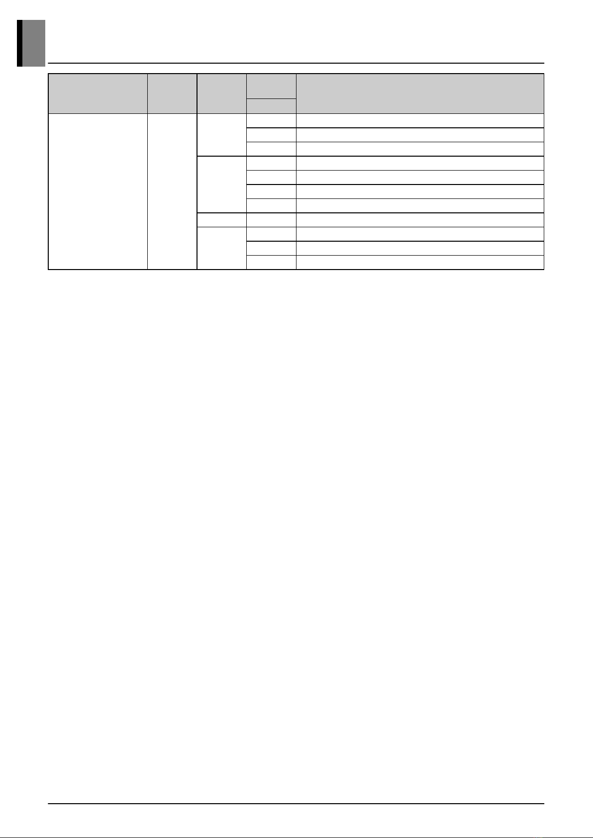
manuals.online logo
Brands
  1. Home
  2. •
  3. Brands
  4. •
  5. LG
  6. •
  7. Heat Pump
  8. •
  9. LG Multi V ZRUM080LTE6 Product guide

LG Multi V ZRUM080LTE6 Product guide

This manual suits for next models

10

Other LG Heat Pump manuals

LG THERMA V User manual

LG

LG THERMA V User manual

LG Therma V 5BPM5-01B Product guide

LG

LG Therma V 5BPM5-01B Product guide

LG THERMA V HM093MR User manual

LG

LG THERMA V HM093MR User manual

LG HM031M Product guide

LG

LG HM031M Product guide

LG Hydro Kit IWT User manual

LG

LG Hydro Kit IWT User manual

LG THERMA V AHUW126A3 User manual

LG

LG THERMA V AHUW126A3 User manual

LG AUUW09GAE(LUU097HV) User manual

LG

LG AUUW09GAE(LUU097HV) User manual

LG MULTI F MAX Installation and operation manual

LG

LG MULTI F MAX Installation and operation manual

LG Therma V Monobloc Series User manual

LG

LG Therma V Monobloc Series User manual

LG PRHR Series User manual

LG

LG PRHR Series User manual

LG MULTI V S ARUN072BSS5 Installation and operation manual

LG

LG MULTI V S ARUN072BSS5 Installation and operation manual

LG Multi IV Installation and operation manual

LG

LG Multi IV Installation and operation manual

LG MULTI V WATER IV ARWN LAS4 Series User manual

LG

LG MULTI V WATER IV ARWN LAS4 Series User manual

LG ARUM080LTE5 Product guide

LG

LG ARUM080LTE5 Product guide

LG MULTI V ARUN072BTE4 User manual

LG

LG MULTI V ARUN072BTE4 User manual

LG DMC24DB-1 User manual

LG

LG DMC24DB-1 User manual

LG Therma V R32 User manual

LG

LG Therma V R32 User manual

LG Multi V BR Series User manual

LG

LG Multi V BR Series User manual

LG THERMA V User manual

LG

LG THERMA V User manual

LG Therma V AHUW096A3 User manual

LG

LG Therma V AHUW096A3 User manual

LG LD097HV4 Installation and operation manual

LG

LG LD097HV4 Installation and operation manual

LG MULTI V S 0CVM0-05A Product guide

LG

LG MULTI V S 0CVM0-05A Product guide

LG ARNU12GSER1 User manual

LG

LG ARNU12GSER1 User manual

LG MULTI F Series User manual

LG

LG MULTI F Series User manual

Popular Heat Pump manuals by other brands

Daikin RXL12QMVJU Service manual

Daikin

Daikin RXL12QMVJU Service manual

AIREDALE BluCube CUR092V16-1CO-0 Installation and maintenance manual

AIREDALE

AIREDALE BluCube CUR092V16-1CO-0 Installation and maintenance manual

Calyenty RBH 125 Customer's manual

Calyenty

Calyenty RBH 125 Customer's manual

GRE HPGI50 owner's manual

GRE

GRE HPGI50 owner's manual

Carrier 30XW Installation, operation and maintenance instructions

Carrier

Carrier 30XW Installation, operation and maintenance instructions

Hayward SUMHEAT HP5131DT3 Installation instructions manual

Hayward

Hayward SUMHEAT HP5131DT3 Installation instructions manual

REMKO SQW 400 Electrical wiring

REMKO

REMKO SQW 400 Electrical wiring

Sanyo SAP120FCH Service manual

Sanyo

Sanyo SAP120FCH Service manual

Daikin EHYHBH05AA Operation manual

Daikin

Daikin EHYHBH05AA Operation manual

Panasonic WH-SDF03E3E5 Design handbook

Panasonic

Panasonic WH-SDF03E3E5 Design handbook

Airxcel 45000 Series Installation, operation and maintenance instructions

Airxcel

Airxcel 45000 Series Installation, operation and maintenance instructions

Mitsubishi Electric PUZ-SWM60VAA Service manual

Mitsubishi Electric

Mitsubishi Electric PUZ-SWM60VAA Service manual

Dimplex LI 16I-TUR Installation and operating instruction

Dimplex

Dimplex LI 16I-TUR Installation and operating instruction

Carrier WSHP Open v3 Integration guide

Carrier

Carrier WSHP Open v3 Integration guide

Mitsubishi Electric EHSE-YM9EC Service manual

Mitsubishi Electric

Mitsubishi Electric EHSE-YM9EC Service manual

TGM CTV14CN018A Technical manual

TGM

TGM CTV14CN018A Technical manual

Carrier 38MGQ Series installation instructions

Carrier

Carrier 38MGQ Series installation instructions

Kokido K2O K880BX/EU Owner's manual & installation guide

Kokido

Kokido K2O K880BX/EU Owner's manual & installation guide

manuals.online logo
manuals.online logoBrands
  • About & Mission
  • Contact us
  • Privacy Policy
  • Terms and Conditions

Copyright 2025 Manuals.Online. All Rights Reserved.

Multi V Outdoor Unit
Heat Recovery + Heat Pump (R32)
MFL67474088
Region : EU
Published on Feb. 2, 2024
Model Line Up
Combination of Outdoor Units
Multi V Outdoor Unit
General Information
Product Phase Chassis
Capacity
Index Model Name
HP
Multi V i 3
UXA(α)
8 ZRUM080LTE6
10 ZRUM100LTE6
12 ZRUM120LTE6
UXB(α)
14 ZRUM140LTE6
16 ZRUM160LTE6
18 ZRUM180LTE6
20 ZRUM200LTE6
UXA + UXA 22 ZRUM220LTE6
UXB + UXA
24 ZRUM240LTE6
26 ZRUM260LTE6
28 ZRUM280LTE6
* The capacity index may differ from actual capacity values.
Multi V Outdoor Unit
1. Model Line Up
General Information
1
Model Name Combination Unit
Unit 1 Unit 2 Unit 3 Unit 4
ZRUM220LTE6 ZRUM100LTE6 ZRUM120LTE6 - -
ZRUM240LTE6 ZRUM100LTE6 ZRUM140LTE6 - -
ZRUM260LTE6 ZRUM120LTE6 ZRUM140LTE6 - -
ZRUM280LTE6 ZRUM120LTE6 ZRUM160LTE6 - -
Multi V Outdoor Unit
2. Combination of Outdoor Units
General Information
2
Multi V i
Product Data
1. Specifications
2. List of Functions
3. Accessory Compatibility List
4. Dimensions
5. Piping Diagrams
6. Wiring Diagrams
7. Capacity Tables
8. Capacity Correction Factor
9. Operation Limits
10. Sound Levels
Multi V i
1.1 Product
ZRUM080LTE6
Category
Unit Specification
Major Minor
Classification
Chassis - UXA
Combination Unit (1) - ZRUM080LTE6
Combination Unit (2) - -
Combination Unit (3) - -
Combination Unit (4) - -
Power Supply
Case 1 V, Phase, Hz 380-400-415, 3, 50
Limit Range of Voltage(Case 1) V 342 ~ 456
Case 2 V, Phase, Hz 380, 3, 60
Limit Range of Voltage(Case 2) V 342 ~ 418
Running Current by Voltage (Cooling,Rated) A 9.97 - 9.47 - 9.13
Running Current by Voltage (Heating,Rated) A 8.43 - 8.01 - 7.72
Cooling Capacity Rated
kW 22.4
Btu/h 76,400
Heating Capacity
Rated
kW 22.4
Btu/h 76,400
Max
kW 25.2
Btu/h 86,000
Power Input(Cooling) Rated kW 6.10
Power Input(Heating) Rated kW 5.16
Efficiency
EER(Rated) W/W 3.67
COP(Rated) W/W 4.34
SEER Wh/Wh 8.28
SCOP Wh/Wh 4.45
Power Factor(Cooling/Heating) Rated - 0.93 / 0.93
Outdoor Fan
Type - Propeller fan
Air Flow Rate(High) m³/min 220
Max. External Static Pressure Pa 80
Discharge direction(Side / Top) - Top
Outdoor Fan Motor
Type - BLDC
Drive - Direct
Output W x No. 1,200 x 1
Compressor
Type - Hermetically Sealed Scroll
Piston Displacement cm³/rev 62.1
Number of Revolution rev./min 3,600
Motor Output W x No. 5,300 × 1
Starting Method - Inverter
Oil Type - FW68L(PVE)
Heat Exchanger
Type - Fin & Tube
No. - 1
Fin Type - Wide Louver Plus
Dimensions
Net(W x H x D) mm 930 x 1,745 x 760
Shipping(W x H x D) mm 965 x 1,919 x 802
Weight
Net kg 215
Shipping kg 225
Exterior
Color - Morning Gray / Dawn Gray
RAL (Classic) - RAL 7038 / RAL 7037
Protection Device
High Pressure Prevention - High pressure sensor / High pressure switch
Frost Prevention - O (Logical)
Discharge Tempreature Control - O (Logical)
Multi V i
1. Specifications
Product Data
1-1
Category
Unit Specification
Major Minor
Protection Device Compressor/Fan Protection - Over-heat protection / Fan driver overload protector
Inverter Protection - Over-heat protection / Over-current protection
Refrigerant
Type - R32
Precharged Amount kg 7.5
GWP(Global Warming Potential) - 675
t-CO₂ eq. - 5.063
Control Type - EEV
Connecting Pipe
Liquid mm(inch) Φ9.52 (3/8)
Gas mm(inch) Φ19.05 (3/4)
Low Pressure Gas (Heat Recovery) mm(inch) Φ19.05 (3/4)
High Pressure Gas (Heat Recovery) mm(inch) Φ15.88 (5/8)
Piping Connection Type
Liquid - Brazing
Gas - Brazing
Low Pressure Gas (Heat Recovery) - Brazing
High Pressure Gas (Heat Recovery) - Brazing
Sound Pressure Level (Outdoor Unit) Cooling / Heating dB(A) 57.0 / 58.0
Measurement Standard (Pressure Leve
l) - - ISO 3745
Sound Power Level (Outdoor Unit) Cooling / Heating dB(A) 78.0 / 78.0
Measurement Standard (Power Level) - - ISO 9614
Connecting Cable Communication Cable(VCTF-SB) mm² × cores 0.75 ~ 1.5 x 2C
Electrical Characteristic
Minimium Circuit Amperes (MCA) A 18.2
Maximum Fuse Amperes (MFA) A 20.0
Total Over Current Amperes (TOCA) A 20.0
Comp_Maximum Starting Current (MSC) A 5.9
Comp_Rated Load Amperes (Cooling) A 7.5
Comp_Rated Load Amperes (Heating) A 5.9
Outdoor Fan Motor_Full Load Amperes (FLA) A 2.5
Connectable indoor units number Max. (Conditional) Units 13(20)
Note
■Due to our policy of innovation some specifications may be changed without notification.
■Wiring cable size must comply with the applicable local and national codes. And “Electric characteristics” should be considered for electrical work and design.
Especially the power cable and circuit breaker should be selected in accordance with that.
■Power factor could vary less than ±1% according to the operating conditions.
■Sound level values are depend on the ambient conditions and values are normally higher in actual operation.
Sound values of combination model are calculated values based on sound results of independent models.
Sound values can be increased owing to ambient or installation conditions during operation.
Sound values of system [dB(A)] = 10*log [10^(A1/10)+ ... +10^(An/10)] , A1~An means sound values of independent models.
■EUROVENT Test Condition :
-Performance values on the this PDB are based on Ceiling Mounted Cassette combination.
-Refer to EUROVENT web site (www.eurovent-certification.com) for other indoor unit combination and more detail test conditions.
■Use appropriate power source refer to national standard.
■Voltage supplied to the unit terminals should be within the minimum and maximum range.
■Maximum allowable voltage unbalance between phase is 2%.
■MSC means the Max. current during the starting of compressor.
MSC and RLA are measured as the compressor only test condition.
OFM are measured as the outdoor unit test condition.
TOCA means the total over current value of each outdoor unit.
Select the wire size based on the larger value among MCA or TOCA.
MFA is used to select the circuit breaker and ground fault circuit interrupter, and all installation site must require attachment of an earth leakage breaker.
[circuit breaker type is ELCB(Earth Leakage Circuit Breaker)].
■Performances are based on the following conditions :
- Cooling : Indoor Ambient Temp. 27°CDB / 19°CWB, Outdoor Ambient Temp. 35°CDB / 24°CWB
- Heating : Indoor Ambient Temp. 20°CDB / 15°CWB, Outdoor Ambient Temp. 7°CDB / 6°CWB
- Interconnected Pipe Length is 7.5m and difference of Elevation (Outdoor ~ Indoor Unit) is 0m.
Multi V i
1. Specifications
Product Data
1-2
ZRUM100LTE6
Category
Unit Specification
Major Minor
Classification
Chassis - UXA
Combination Unit (1) - ZRUM100LTE6
Combination Unit (2) - -
Combination Unit (3) - -
Combination Unit (4) - -
Power Supply
Case 1 V, Phase, Hz 380-400-415, 3, 50
Limit Range of Voltage(Case 1) V 342 ~ 456
Case 2 V, Phase, Hz 380, 3, 60
Limit Range of Voltage(Case 2) V 342 ~ 418
Running Current by Voltage (Cooling,Rated) A 13.61 - 12.39 - 12.47
Running Current by Voltage (Heating,Rated) A 10.17 - 9.66 - 9.31
Cooling Capacity Rated
kW 28.0
Btu/h 95,500
Heating Capacity
Rated
kW 28.0
Btu/h 95,500
Max
kW 31.5
Btu/h 107,500
Power Input(Cooling) Rated kW 8.33
Power Input(Heating) Rated kW 6.22
Efficiency
EER(Rated) W/W 3.36
COP(Rated) W/W 4.50
SEER Wh/Wh 8.11
SCOP Wh/Wh 4.52
Power Factor(Cooling/Heating) Rated - 0.93 / 0.93
Outdoor Fan
Type - Propeller fan
Air Flow Rate(High) m³/min 220
Max. External Static Pressure Pa 80
Discharge direction(Side / Top) - Top
Outdoor Fan Motor
Type - BLDC
Drive - Direct
Output W x No. 1,200 x 1
Compressor
Type - Hermetically Sealed Scroll
Piston Displacement cm³/rev 62.1
Number of Revolution rev./min 3,600
Motor Output W x No. 5,300 x 1
Starting Method - Inverter
Oil Type - FW68L(PVE)
Heat Exchanger
Type - Fin & Tube
No. - 1
Fin Type - Wide Louver Plus
Dimensions
Net(W x H x D) mm 930 x 1,745 x 760
Shipping(W x H x D) mm 965 x 1,919 x 802
Weight
Net kg 215
Shipping kg 225
Exterior
Color - Morning Gray / Dawn Gray
RAL (Classic) - RAL 7038 / RAL 7037
Protection Device
High Pressure Prevention - High pressure sensor / High pressure switch
Frost Prevention - O (Logical)
Discharge Tempreature Control - O (Logical)
Compressor/Fan Protection - Over-heat protection / Fan driver overload protector
Inverter Protection - Over-heat protection / Over-current protection
Multi V i
1. Specifications
Product Data
1-3
Category
Unit Specification
Major Minor
Refrigerant
Type - R32
Precharged Amount kg 8.5
GWP(Global Warming Potential) - 675
t-CO₂ eq. - 5.738
Control Type - EEV
Connecting Pipe
Liquid mm(inch) Φ9.52 (3/8)
Gas mm(inch) Φ19.05 (3/4)
Low Pressure Gas (Heat Recovery) mm(inch) Φ19.05 (3/4)
High Pressure Gas (Heat Recovery) mm(inch) Φ15.88 (5/8)
Piping Connection Type
Liquid - Brazing
Gas - Brazing
Low Pressure Gas (Heat Recovery) - Brazing
High Pressure Gas (Heat Recovery) - Brazing
Sound Pressure Level (Outdoor Unit) Cooling / Heating dB(A) 57.5 / 58.5
Measurement Standard (Pressure Leve
l) - - ISO 3745
Sound Power Level (Outdoor Unit) Cooling / Heating dB(A) 79.0 / 79.0
Measurement Standard (Power Level) - - ISO 9614
Connecting Cable Communication Cable(VCTF-SB) mm² × cores 0.75 ~ 1.5 x 2C
Electrical Characteristic
Minimium Circuit Amperes (MCA) A 25.1
Maximum Fuse Amperes (MFA) A 32
Total Over Current Amperes (TOCA) A 28.0
Comp_Maximum Starting Current (MSC) A 5.9
Comp_Rated Load Amperes (Cooling) A 11.1
Comp_Rated Load Amperes (Heating) A 7.7
Outdoor Fan Motor_Full Load Amperes (FLA) A 2.5
Connectable indoor units number Max. (Conditional) Units 16(25)
Note
■Due to our policy of innovation some specifications may be changed without notification.
■Wiring cable size must comply with the applicable local and national codes. And “Electric characteristics” should be considered for electrical work and design.
Especially the power cable and circuit breaker should be selected in accordance with that.
■Power factor could vary less than ±1% according to the operating conditions.
■Sound level values are depend on the ambient conditions and values are normally higher in actual operation.
Sound values of combination model are calculated values based on sound results of independent models.
Sound values can be increased owing to ambient or installation conditions during operation.
Sound values of system [dB(A)] = 10*log [10^(A1/10)+ ... +10^(An/10)] , A1~An means sound values of independent models.
■EUROVENT Test Condition :
-Performance values on the this PDB are based on Ceiling Mounted Cassette combination.
-Refer to EUROVENT web site (www.eurovent-certification.com) for other indoor unit combination and more detail test conditions.
■Use appropriate power source refer to national standard.
■Voltage supplied to the unit terminals should be within the minimum and maximum range.
■Maximum allowable voltage unbalance between phase is 2%.
■MSC means the Max. current during the starting of compressor.
MSC and RLA are measured as the compressor only test condition.
OFM are measured as the outdoor unit test condition.
TOCA means the total over current value of each outdoor unit.
Select the wire size based on the larger value among MCA or TOCA.
MFA is used to select the circuit breaker and ground fault circuit interrupter, and all installation site must require attachment of an earth leakage breaker.
[circuit breaker type is ELCB(Earth Leakage Circuit Breaker)].
■Performances are based on the following conditions :
- Cooling : Indoor Ambient Temp. 27°CDB / 19°CWB, Outdoor Ambient Temp. 35°CDB / 24°CWB
- Heating : Indoor Ambient Temp. 20°CDB / 15°CWB, Outdoor Ambient Temp. 7°CDB / 6°CWB
- Interconnected Pipe Length is 7.5m and difference of Elevation (Outdoor ~ Indoor Unit) is 0m.
Multi V i
1. Specifications
Product Data
1-4