manuals.online logo
Brands
  1. Home
  2. •
  3. Brands
  4. •
  5. LG
  6. •
  7. Heat Pump
  8. •
  9. LG 5BPU0-02D Product guide

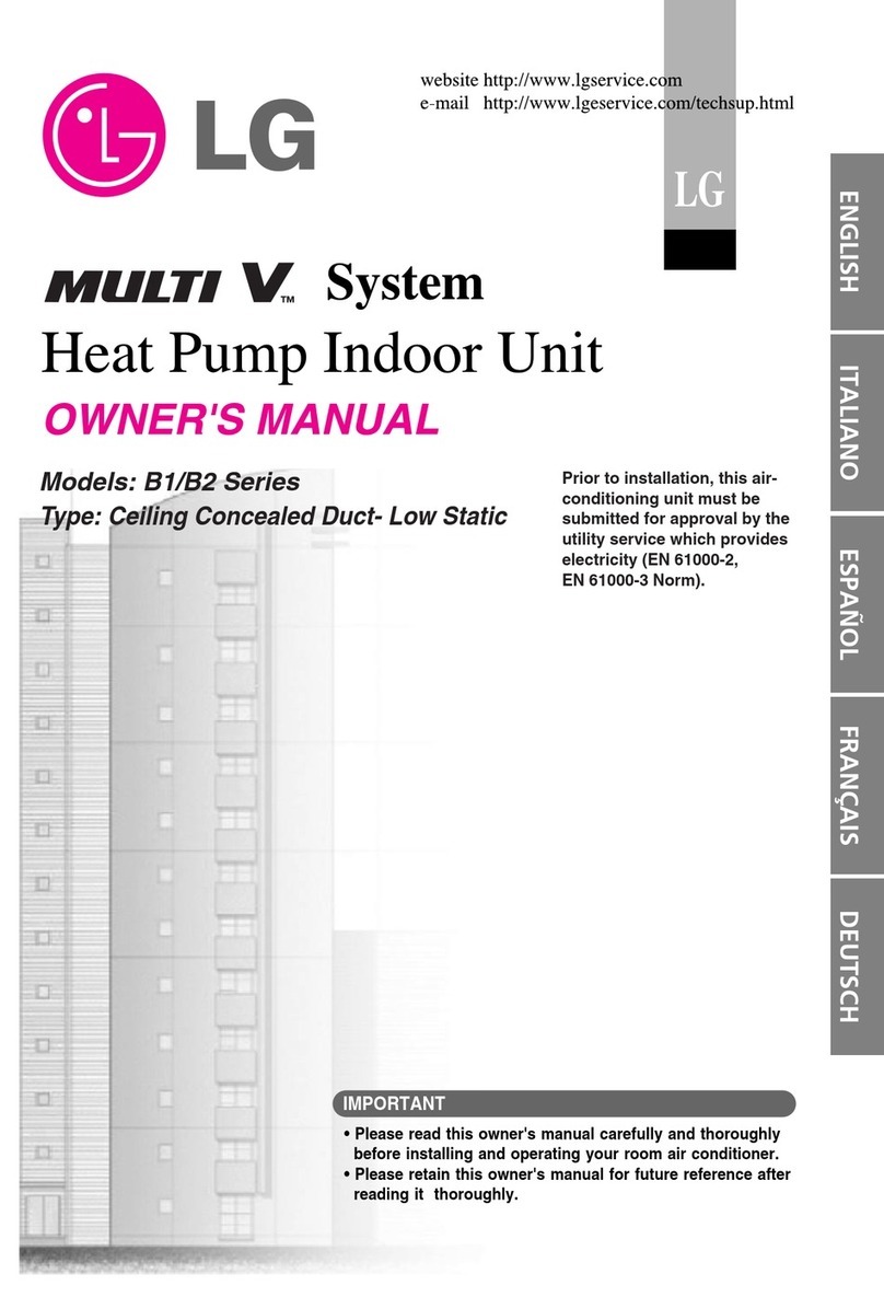
LG 5BPU0-02D Product guide

Air-to-Water Heat Pump / Split Type
R410A/50Hz
5BPU0-02D (Replaces 5BPU0-02C)
P/No. : MFL66101112
THERMA V
Split Type
General Information
Indoor Unit
Hydro Box Unit
DHW Tank Integrated Unit
Outdoor unit
Design and installation
General Information
THERMA V
Split Type
1.Model Line Up
2.Nomenclature
2
THERMA V Split Type General Information
1. Model line up
1.1 Indoor Units
Note
* : Actual system capacity would be different accordance with combination of outdoor unit.
1.2 Outdoor Units
Category Type External
Appearance
Heater
Capacity
[kW]
Model Name
Features
Heating Capacity
class* (kW)
16.0
AWHP Split Type
Hydro Box Type
6.0 AHNW16606A3
[HN1616 NK3]
• Prividing eco-friendly heating
• High energy efficiency
• Easy installation
• Space heating, cooling, and Domestic Hot
Water heating
9.0 AHNW16809A3
[HN1639 NK3]
DHW Tank
Integrated Type 6.0 AHNW16606B0
[HN1616T NB0]
• Providing Eco-friendly heating
• High energy efficiency
– Pressure Control & Quick Operating
Response
• Quiet operation
• All in one solution
– Hydro Box for Space heating/cooling +
Domestic How Water Tank + Buffer Tank
– Small space for product installation
– Easy and quick installation
• Weather dependent operation
Category
Model Name
Heating Capacity (kW)
5.0 7.0 9.0 12.0 14.0 16.0
1 Phase Model
1 Ø, 220-240 V, 50 Hz
AHUW056A3
[HU051 U43]
AHUW076A3
[HU071 U43]
AHUW096A3
[HU091 U43]
AHUW126A3
[HU121 U33]
AHUW146A3
[HU141 U33]
AHUW166A3
[HU161 U33]
Combination
AHNW16606A3
[HN1616 NK3] OOOOOO
AHNW16606B0
[HN1616T NB0] - - OOOO
3 Phase Model
3 Ø, 380-415 V, 50 Hz ---
AHUW128A3
[HU123 U33]
AHUW148A3
[HU143 U33]
AHUW168A3
[HU163 U33]
Combination
AHNW16809A3
[HN1639 NK3] ---OOO
AHNW16606B0
[HN1616T NB0] ---OOO
External Appearanceଝ
3
THERMA V Split Type General Information
2. Nomenclature
2.1 Indoor Unit
Global Name
Model
Name AH N W 16 6 06 A 3
No.12345678
No. Signification
1Air-to-Water Heat Pump for R410A
2
Classification
N : Indoor unit of Split type
U : Outdoor unit of Split type
B : Monobloc type
3
Model Type
W : Inverter Heat Pump
H : Heat Pump
4Heating Capacity (kW)
Ex) 9kW ˧ '09', 12kW ˧ '12'
5
Heater Electrical ratings
6 : 1Ø, 220-240V, 50 Hz
8 : 3Ø, 380-415V, 50Hz
A : 3Ø, 220V, 50Hz
6
Heater Capacity (kW)
06 : 6kW Heater
09 : 9kW Heater
7
Function
A : General heating heat pump
H : Domestic Hot heating only
T : High temperature heating heat pump
B : DHW tank integrated model
8Serial number
3 Series
THERMA V Split Type
2. Nomenclature
4
General Information
European Name
Model
Name H N 16 1 6 T . N B 0
No.123456* 789
No. Signification
1Air-to-Water Heat Pump for R410A
2
Classification
N : Indoor unit of Split type
U : Outdoor unit of Split type
M : Monobloc type
3Heating Capacity (kW)
Ex) 9kW ˧ '09', 12kW ˧ '12'
4
Heater Electrical ratings
1 : 1Ø, 220-240V, 50 Hz
2 : 3Ø, 220V, 50Hz
3 : 3Ø, 380-415V, 50Hz
5
Nominal Heater Capacity (kW)
00 : None Heater
04 : 4kW heater
6*
Functions
T : DHW tank integrated model
H : High Temperature heating model
(* In case of Hydro Box Low temperature type, here is blank.)
7
Classification
N : Indoor unit of Split type
U : Outdoor unit of Split type
M : Monobloc type
8
Platform (Chassis code)
K : K2,K3 Chassis
B : DHW tank integrated Flatform
9Serial number
2. Nomenclature
5
THERMA V Split Type General Information
2.2 Outdoor Unit
Global Name
Model
Name AH U W 09 6 A 3
No.1234567
No. Signification
1Air-to-Water Heat Pump for R410A
2
Classification
N : Indoor unit
U : Outdoor unit
இ: Set
3
Model Type
W : Inverter Heat Pump
H : Heat Pump
4Heating Capacity (kW)
Ex) 5kW : ‘05’, 16kW : '16'
5
Electrical ratings
6 : 1Ø, 220-240V AC 50 Hz
8 : 3Ø, 380-415V AC 50 Hz
6
Function
A : General heating heat pump
H : Domestic Hot heating only
T : High temperature heating heat pump
7Serial number
3 Series
THERMA V Split Type
2. Nomenclature
6
General Information
European Name
Model
Name H U 05 1 . U 4 3
No.1234 567
No. Signification
1H : Air-to-Water Heat Pump for R410A
2Classification
U : Outdoor unit
3Heating Capacity (kW)
Ex) 5kW : ‘05’, 16kW : '16'
4
Electrical ratings
1 : 1Ø, 220-240V AC 50 Hz
3 : 3Ø, 380-415V AC 50 Hz
5
Classification
N : Indoor unit of Split type
U : Outdoor unit of Split type
M : Monobloc type
6
Platform (Chassis code)
4 : U4 Chassis
3 : U3 Chassis
7Serial number
Indoor Unit
THERMA V
Split Type
Hydro Box Unit
DHW Tank Integrated Unit
Hydro Box Unit
THERMA V
Split Type
1.List of Functions
2.Specification
3.Dimensions
4.Wiring Diagram
5.Piping Diagram
6.Hydraulic Performance
7.Sound Levels
2
THERMA V Split Type Hydro Box Unit
1. List of Functions
Basic functions of Unit
Note
1. O : Applied, X : Not applied
Accessory : Ordered and purchased separately the accessory package referring to the model name provided and install at field.
Accessory line-ups varies by region, so check your local catalogue or local sales material.
Category Function AHNW16606A3 [HN1616 NK3]
AHNW16809A3 [HN1639 NK3]
Installation
Drain pump X
E.S.P. control X
Electric heater(operation) O
High ceiling operation X
Reliability
Hot start X
Self diagnosis O
Soft dry operation X
Convenience
Auto changeover X
Auto cleaning X
Auto operation(artificial intelligence) X
Auto restart operation O
Child lock O
Forced operation X
Group control X
Sleep mode O
Timer(on/off) O
Timer(weekly) O
Two thermistor control X
Individual control
Standard wired remote controller (control panel) O
Premium wired remote controller X
Simple wired remote controller X
Simple wired remote controller (for hotel use) X
Wireless remote controller (simple) X
Air to Water Heat Pump
Functions
Anti-Condensation on floor (cooling) O
Water Pump ON / OFF Control O
Flow Switch Control O
Thermostat Interface (230V AC) O
Thermostat Interface (24V AC) X
PHEX Anti-Freezing Control O
Water Pump Forced Operation O
Autosetting according to Ambient Temperature O
Silent Operation O
Anti-overheating of Water Pipe O
Emergency Operation O
Weather Dependent Operation with Thermostat O
Scheduler(Domestic Hot Water Tank Heater) O
Timer(Domestic Hot Water Tank Heater) O
Quick Domestic Hot Water Tank Heating O
Electric Heater Capacity Control O
Screed Drying Mode O
Sump Heater O
Dry Contact (Main PCB) O
1. List of Functions
3
THERMA V Split Type Hydro Box Unit
Accessory Compatibility List
Note
1. O: Possible, X: Impossible, - : Not applicable
2. * : Some advanced functions controlled by individual controller cannot be operated.
3. ** : ACP, AC Smart, ACP BACnet or ACP Lonworks is needed.
4. If you need more detail, please refer to the manual of product.
(http://partner.lge.com/global : Home> Doc.Library> Product > Control(BECON)))
*** Meter interface cannot be connected at the same time with 3rd-party controller.
Category Product Remark AHNW16606A3 [HN1616 NK3]
AHNW16809A3 [HN1639 NK3]
Dry Contact
Simple Contact PDRYCB000 Simple Dry Contact O
Communication Type
PDRYCB400 2 Points Dry Contact
(For Setback) X
PDRYCB300 8 Points Dry Contact
(For Thermostat) O
PDRYCB500 Dry Contact for Modbus X
ETC
Remote temperature sensor PQRSTA0 - O
Zone Controller ABZCA - X
Group control wire PZCWRCG3 0.25 m X
2-Remo Control Wire PZCWRC2 0.25 m
Extension wire PZCWRC1 10 m
Wi-Fi controller * PWFMDD200 - O
Meter Interface Module *** PENKTH000 Interface between IDU and Meter O
Accessory Kit
for AWHP
DHW tank kit (Split) PHLTA For Split O
DHW sensor PHRSTA0 included in PHLTA kit O
DHW tank kit (Monobloc) PHLTB For Monobloc X
Solar thermal kit PHLLA - O (Limit Temp. : 96 ୅)
2nd Circuit Thermistor PRSTAT5K10 - O
Backup heater HA031M E1 /
HA061M E1 -X
Drain pan PHDPB - O
Gateway
IDU PI485 PHNFP14A0 Connected with Indoor Units X
ODU PI485 PMNFP14A1 PI 485 Gateway X
BACnet PQNFB17C0 ACP BACnet X
Lonworks PLNWKB000 ACP Lonworks X
4
THERMA V Split Type Hydro Box Unit
2. Specifications
Indoor Units AHNW16606A3
[HN1616 NK3]
AHNW16809A3
[HN1639 NK3]
Combination Outdoor Units
AHUW056A3 [HU051 U43]
AHUW076A3 [HU071 U43]
AHUW096A3 [HU091 U43]
AHUW126A3 [HU121 U33]
AHUW146A3 [HU141 U33]
AHUW166A3 [HU161 U33]
AHUW128A3 [HU123 U33]
AHUW148A3 [HU143 U33]
AHUW168A3 [HU163 U33]
Operation
Range
(Leaving
Water)
Cooling For Fan Coil Unit Min. ~ Max. °C 6~30 6~30
For under floor Min. ~ Max. °C 16~30 16~30
Heating
For Fan Coil Unit /
Radiator Min. ~ Max. °C 15~57( * 20~55୅) 15~57( * 20~55୅)
For under floor Min. ~ Max. °C 15~57( * 20~55୅) 15~57( * 20~55୅)
Water Pump
Type - Non-Self-Priming Type
of DC Pump
Non-Self-Priming Type
of DC Pump
Motor type - BLDC BLDC
Number of Revolution (setting range) RPM 500 ~ 3,500 500 ~ 3,500
Power input Rated W 130 130
Water Flow Rate Rated ˜/min 46 46
Heat
Exchanger
Type - Brazed Plate HEX Brazed Plate HEX
Quantity - 1 1
Number of Plate EA 76 76
Water Flow
Rate Heating Rated ˜/min 46.0 46.0
Expansion
Vessel
Volume ˜8.0 8.0
Water Pressure Max. bar 3 3
Water Pressure Pre-charged bar 1 1
Strainer Mesh size - 28 mesh 28 mesh
Material - Stainless Steel Stainless Steel
Safety Valve Pressure Limit Upper Limit bar 3 3
Devices for Water Circuit
- Manometer
- Drain Valve / Fill Valve
- Shut Off Valve
- Air Vent
Piping
Connections
Water
Circuit
Inlet Inner Dia. mm(inch) Male PT 25(1) Male PT 25(1)
Outlet Inner Dia. mm(inch) Male PT 25(1) Male PT 25(1)
Refrigerant
Circuit
Gas Outer Dia. mm(inch) Ø 15.88 (5/8) Ø 15.88 (5/8)
Liquid Outer Dia. mm(inch) Ø 9.52 (3/8) Ø 9.52 (3/8)
Sound Power
Level Heating Rated dB(A) 44 44
Dimensions Unit W x H x D mm 490 x 850 x 315 490 x 850 x 315
Packed Unit W x H x D mm 563 x 1082 x 375 563 x 1082 x 375
Weight
(Without water)
Unit kg 43.5 45.0
Packed Unit kg 49.5 51.0
DHW Tank**
(Field Supply)
Type - Indirect heating
(+Electric heater)
Indirect heating
(+Electric heater)
Heater Capacity Max. kW 3 3
Power Supply V / Ø / Hz 230 / 1 / 50 230 / 1 / 50
Power Supply Type - Separated power source Separated power source
Thermal Protector Range Max. °C 90 90
Relay Contactor - Needed Needed
ELCB A 40 40
Sensor Adaptor Diameter mm(inch) 12.7 (1/2) 12.7 (1/2)
Accessory Kit Model Name*** - PHLTA (LG Supply) PHLTA (LG Supply)
MCCB A 32 32
2. Specifications
5
THERMA V Split Type Hydro Box Unit
Note
1. Due to our policy of innovation some specifications may be changed without notification.
2. Wiring cable size must comply with the applicable local and national codes. And “Electric characteristics” chapter should be considered for electrical
work and design. Especially the power cable and circuit breaker should be selected in accordance with that.
3. Sound Level Values are measured at Noise Measuring chamber accordance with standard. Therefore, these values depend on the ambient conditions
and values are normally higher in actual operation.
4. Performances are based on the following conditions :
• Cooling : Inlet/Outlet Water Temp. 23°C/18°C, Outdoor Air Temp. 35°CDB / 24°CWB
• Heating : Inlet/Outlet Water Temp. 30°C/35°C, Outdoor Air Temp. 7°CDB / 6°CWB
• Interconnected Pipe Length is standard length and difference of Elevation (Outdoor ~ Indoor Unit) is Zero.
5. This product contains Fluorinated greenhouse gases.
6. Sound Performances are based on the following conditions.
• Sound Power Level : Measured according to EN14825.
• Sound Pressure Level : Calculated value according to distance of sound power.
* : This specification is data when electric heater is not used.
** : This information is given as a guideline about the connection of DHW tank.
*** : This Accessory Kit is required only when you want to user the electric heater function at DHW tank. If not, it’s not necessary.
Therma V indoor unit it self already has electric heater (back up heating) function.
Electrical Specification AHNW16606A3
[HN1616 NK3]
AHNW16809A3
[HN1639 NK3]
Electric Heater
Type - Sheath Sheath
Number of Heating Coil EA 2 3
Capacity Combination kW 3.0 + 3.0 3.0 + 3.0 + 3.0
Operation - Automatic Automatic
Heating Steps Step 2 2
Power Supply V, Ø, Hz 1, 220-240, 50 3, 380-415, 50
Rated Current A 25.0 25.0
Maximum Current A 32.0 32.0
Wiring
Connections
Power and Communication Cable
(Included Earth)
No. x
mm² 3 x 1.5 (H07RN-F) 3 x 1.5 (H07RN-F)
6
THERMA V Split Type Hydro Box Unit
3. Dimensions
3.1 Internal
AHNW16606A3 [HN1616 NK3], AHNW16809A3 [HN1639 NK3]
484
289.6
484
123
116
84.5
63.4
36.9
46.4
76 41
847.8
Description
No Name Remark
Ø9.52mm
1 Leaving Water Pipe Male PT 1 inch
2 Entering Water Pipe Male PT 1 inch
8 Thermal switch
Ø15.88mm
Max Head 9.5 / 7 / 6 m
Open at water pressure 3 bar
PCB and terminal blocks
3 Refrigerant Pipe
4 Refrigerant Pipe
5 Water Pump
6 Safety Valve
7 Control Box
Cut-off power input to electric heater at 90 °C
(manual return at 55C)
9 Flow Switch Minimum operation range at 15 LPM.
10 Plate Heat Exchanger Heat exchange between refrigerant and water
Indicates circulating water pressure11 Pressure Gage
12 Expansion Tank
13 Air Vent
14 Electric Heater
Absorbing Volume change of heated water
Air purging when Charging water
Please refer to the below Page
‘Model name and related information’
15 Strainer
16 Shut-off valve
Filtering and stacking particles inside circulating water
To drain or to block water when pipe connecting
3. Dimensions
7
THERMA V Split Type Hydro Box Unit
3.2 External
AHNW16606A3 [HN1616 NK3], AHNW16606A3 [HN1616 NK3]
u
XUG|GGGGGGGGGGG
GU
YUG|GGGGGGGGGGGT
GGU
ZUGhGGGGGGGGGGG
GGGGGGUGG
_\WZX\
[`W
[`W
ZX\
k
u u
X j w
y
iT y j
8
THERMA V Split Type Hydro Box Unit
4. Wiring Diagrams
AHNW16606A3 [HN1616 NK3]
4. Wiring Diagrams
9
THERMA V Split Type Hydro Box Unit
AHNW16809A3 [HN1639 NK3]
10
THERMA V Split Type Hydro Box Unit
5. Piping Diagram
AHNW16606A3 [HN1616 NK3] / AHNW16809A3 [HN1639 NK3]
iGG
z
Opk|GRGvk|PG
{
j
ko~G{
m
j
|
|
o
pG|
OoTrP
lwV{hur
~Vw|twX
yGv
mVz
lVo{
yGy
{UGz
z
w
Z~h
}V}X
Y~h
}V}X
jG~
z
Z~h
}V}Y
zvshyG{olyths
zz{lt
~Vw|twY
iVo{
yGp
y
p
ko~G{G
Oko~GG
uP
zGGGG

OzGGG
P
tVm
tGm
OyP
z^
z_
zXX
zXZ
zX[
zXY
z`
zXW
5. Piping Diagram
11
THERMA V Split Type Hydro Box Unit
Category Symbol Meaning PCB Connector Remarks
Indoor Unit
S7 Refrigerant temperature sensor (Gas
side) CN_PIPE_OUT - Meaning is expressed based on Cooling
mode.
S8 Refrigerant temperature sensor
(Liquid side) CN_PIPE_IN
S9 Entering Water temperature sensor
CN_TH3 - S9, S10 and S11 are connected at 6 pin
type connector CN_TH3.
S10 Leaving Water temperature sensor
S11 Electric heater outlet temperature
sensor
F/S Flow Switch CN_FLOW1 ଝ
E/HT Electric Heater CN_E/HEAT(A)
CN_E/HEAT(B)
- Heating capacity is divided into two level :
partial capacity by E/HEAT(A) and full
capacity by E/HEAT(A) + E/HEAT(B).-
Operating power(230 V AC 50 Hz) of
E/HEAT(A) and E/HEAT(B) are supplied by
external power source via relay connector
and ELB.
W_PUMP1 Internal Water Pump CN_MOTOR1 - Water Pump is connected at
CN_MOTOR1
EXP/TANK Expansion Tank (no connector) - Absorb volume change of heated water,
S12 Remote Air temperature sensor CN_ROOM - Optional accessory (sold separately)-
Model : PQRSTA0
CTR/PNL Control Panel (or 'Remote Controller') CN_REMO - Pre built-in at indoor unit
2WAY V/V_1 To control water flow for Fan Coil Unit CN_2WAY(A)
- 3rd party accessory and Field installation
(sold separately)- 2 wire NO or NC type
2way valve is supported.
M / F Magnetic Filter (No connector)
- 3rd party accessory and Field installation
(sold separately)- It is strongly
recommended to install an additional filter
on the heating water circuit.
Water
Heating
W/TANK DHW Tank (No connector)
- 3rd party accessory and Field installation
(sold separately)- Generating and storing
DHW by AWHP or built-in electric heater
B/HT Electric Heater CN_B/HEAT(A)
- 3rd party accessory and Field installation
(usually built-in at W/TANK)- Supplying
additional water heating capacity.
3WAY V/V_1
- Flow control for water which is
leaving from indoor unit.- Flow
direction switching between
underfloor and water tank
CN_3WAY(A)
- 3rd party accessory and Field installation
(sold separately)- SPDT type 3way valve is
supported.
CITY WATER Water to be heated by Indoor unit and
B/HT of W/TANK (no connector) - Field installation
SHOWER Water supplied to end-user (no connector) - Field installation
S13 W/TANK water temperature sensor
CN_TH4
- S13 and S14 are connected at 4 pin type
connector CN_TH4.- S13 is a part of DHW
tank kit.(Model:PHLTA)- S14 is a part of
solar thermal kit (Model:PHLLA)
Solar Heating
S14 Solar-heated water temperature
sensor
3WAY V/V_2
- Flow control for water which is
heated and circulated by SOLAR
THERMAL SYSTEM.- Flow direction
switching between SOLAR THERMAL
SYSTEM and W/TANK
CN_3WAY(B)
- 3rd party accessory and Field installation
(sold separately)- SPDT type 3way valve is
supported.
W_PUMP/2 External Water Pump CN_W/PUMP(B)
- 3rd party accessory and Field installation
(sold separately)- If water pump of SOLAR
THERMAL SYSTEM is incapable of
circulation,external water pump can be
used.
SOLAR
THERMAL
SYSTEM
- This system can include following
components: Solar panel, Sensors,
Thermostats, Interim heat exchanger,
Water pump, etc.- To utilized hot
water heated by SOLAR THERMAL
SYSTEM, end-user must by LG
AWHP Solar-Kit.
(no connector) - 3rd party accessory and Field installation
(sold separately)

This manual suits for next models

1

Other LG Heat Pump manuals

LG Multi V CRNN-SP Series User manual

LG

LG Multi V CRNN-SP Series User manual

LG THERMA V HN1639 User manual

LG

LG THERMA V HN1639 User manual

LG MULTI V ARNU-GVE Series User manual

LG

LG MULTI V ARNU-GVE Series User manual

LG ARNU363SVA4 Installation and operation manual

LG

LG ARNU363SVA4 Installation and operation manual

LG ARNU09GVEA1 User manual

LG

LG ARNU09GVEA1 User manual

LG LS091HSV3 User manual

LG

LG LS091HSV3 User manual

LG THERMA V Air-to-Water Heat Pump User manual

LG

LG THERMA V Air-to-Water Heat Pump User manual

LG THERMA V Series User manual

LG

LG THERMA V Series User manual

LG MULTI V S 0CVM0-05A Product guide

LG

LG MULTI V S 0CVM0-05A Product guide

LG THERMA V HA031M E1 User manual

LG

LG THERMA V HA031M E1 User manual

LG MULTI F MAX Installation and operation manual

LG

LG MULTI F MAX Installation and operation manual

LG Multi F A2UW14GFA0 Product guide

LG

LG Multi F A2UW14GFA0 Product guide

LG ARUV025GSD0 Product guide

LG

LG ARUV025GSD0 Product guide

LG Multi V water mini Series Owner's manual

LG

LG Multi V water mini Series Owner's manual

LG MULTI F Series User manual

LG

LG MULTI F Series User manual

LG MULTI V LRNU18GS3B0 User manual

LG

LG MULTI V LRNU18GS3B0 User manual

LG ARWN038GA2 User manual

LG

LG ARWN038GA2 User manual

LG THERMA V User manual

LG

LG THERMA V User manual

LG HM031M Product guide

LG

LG HM031M Product guide

LG MULTI V LRNN Series User manual

LG

LG MULTI V LRNN Series User manual

LG Therma V R32 User manual

LG

LG Therma V R32 User manual

LG WH20S F5 User manual

LG

LG WH20S F5 User manual

LG THERMA V DHW Tank Kit User manual

LG

LG THERMA V DHW Tank Kit User manual
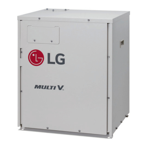
LG Multi V 5 Manual

LG

LG Multi V 5 Manual

Popular Heat Pump manuals by other brands

Carrier 42n manual

Carrier

Carrier 42n manual

TemperZone Magnus MWP Series OWNER APPLICATION & INSTALLATION MANUAL

TemperZone

TemperZone Magnus MWP Series OWNER APPLICATION & INSTALLATION MANUAL

Nordyne Q5RF Series User's manual & installation instructions

Nordyne

Nordyne Q5RF Series User's manual & installation instructions

AQUALUX 106003 Installation and user manual

AQUALUX

AQUALUX 106003 Installation and user manual

Ideal Heating ECOMOD AHP60 26 kW Installation and servicing

Ideal Heating

Ideal Heating ECOMOD AHP60 26 kW Installation and servicing

Daikin Altherma 3 WS Operation manual

Daikin

Daikin Altherma 3 WS Operation manual

Danfoss DHP-M installation guide

Danfoss

Danfoss DHP-M installation guide

AES Remora Professional Series manual

AES

AES Remora Professional Series manual

Dimplex SI 130TE Installation and operating instructions

Dimplex

Dimplex SI 130TE Installation and operating instructions

Ecoer EODA18H-2436 Service manual

Ecoer

Ecoer EODA18H-2436 Service manual

Dimplex LAS 10MT Installation and operating instructions

Dimplex

Dimplex LAS 10MT Installation and operating instructions

Carrier COMFORT SERIES 25HCB3 installation instructions

Carrier

Carrier COMFORT SERIES 25HCB3 installation instructions

Daikin VRV II-Q RQYQ8-48PY1B Service manual

Daikin

Daikin VRV II-Q RQYQ8-48PY1B Service manual

Carrier Aquazone 50RWS036-360 Installation, Start-Up and Service Instructions

Carrier

Carrier Aquazone 50RWS036-360 Installation, Start-Up and Service Instructions

Immergas MAGIS COMBO Instructions and warnings

Immergas

Immergas MAGIS COMBO Instructions and warnings

Carrier 38QB Installation, Start-Up and Service Instructions

Carrier

Carrier 38QB Installation, Start-Up and Service Instructions

Galletti LEP Series Technical manual

Galletti

Galletti LEP Series Technical manual

Carrier weathermaker 38BQ002 use and care manual

Carrier

Carrier weathermaker 38BQ002 use and care manual

manuals.online logo
manuals.online logoBrands
  • About & Mission
  • Contact us
  • Privacy Policy
  • Terms and Conditions

Copyright 2025 Manuals.Online. All Rights Reserved.