1-1
CONTENTS
SECTION 1
GENERAL
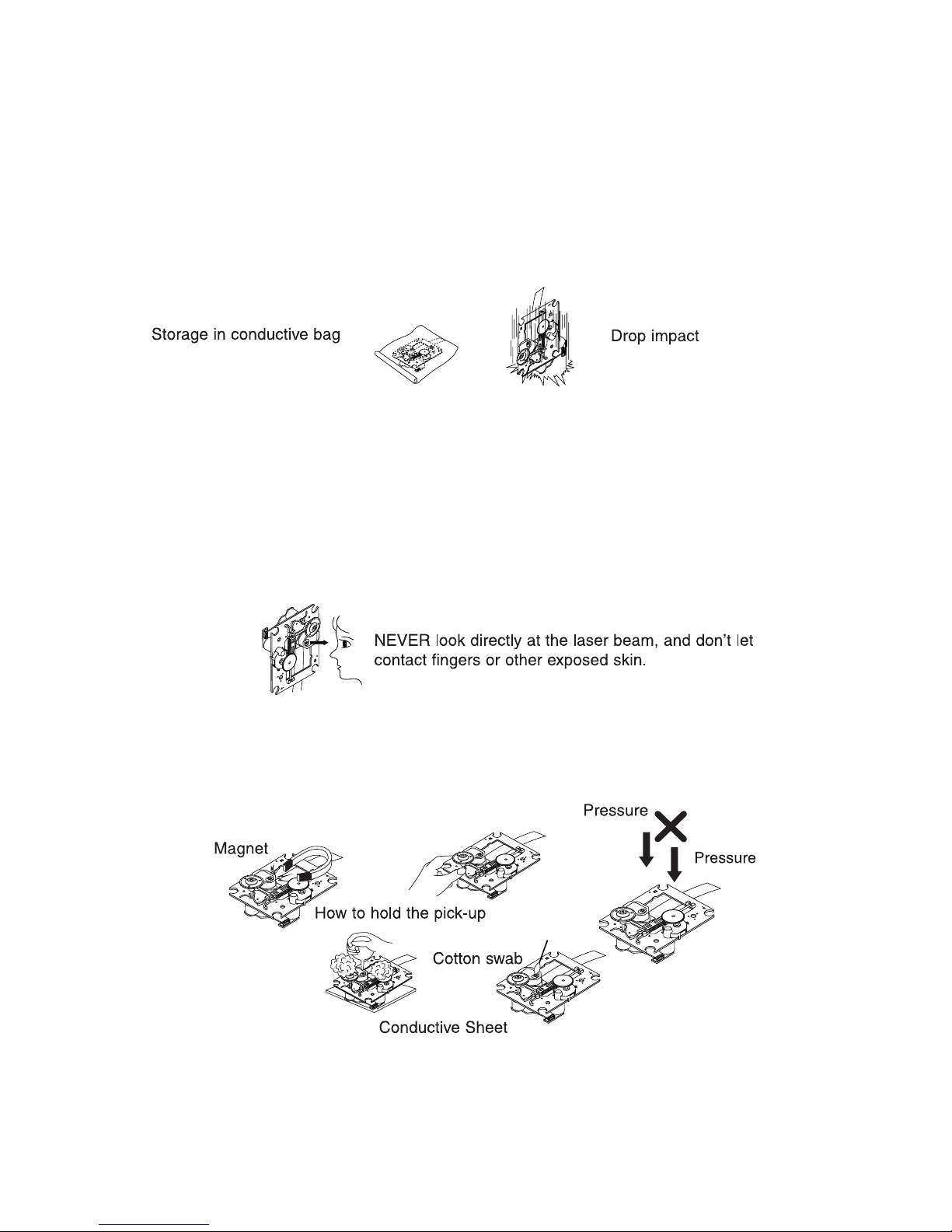
SERVICING PRECAUTIONS ......................................1-2
• NOTES REGARDING HANDLING OF THE PICK-UP
•
NOTES REGARDING COMPACT DISC PLAYER REPAIRS
ESD PRECAUTIONS ...................................................1-4
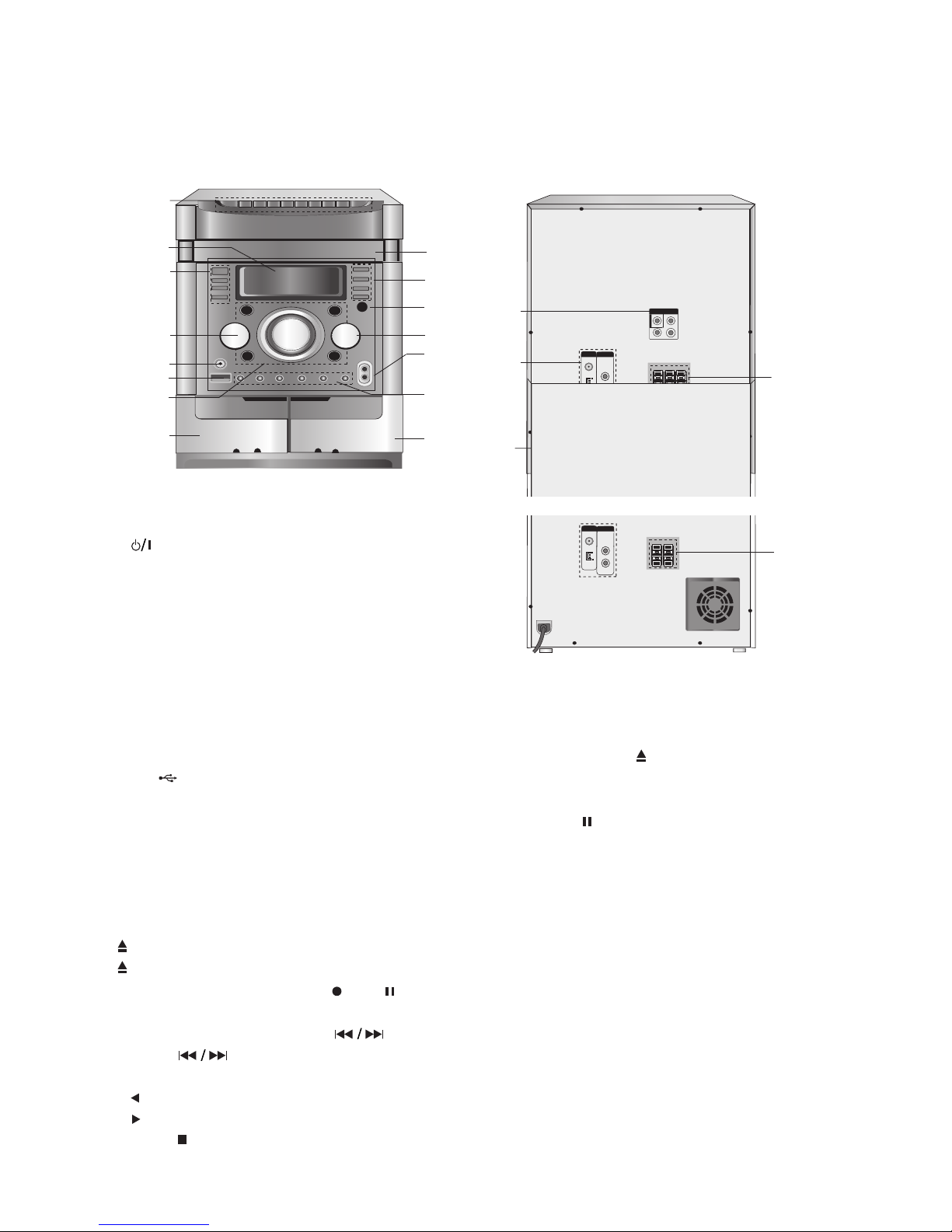
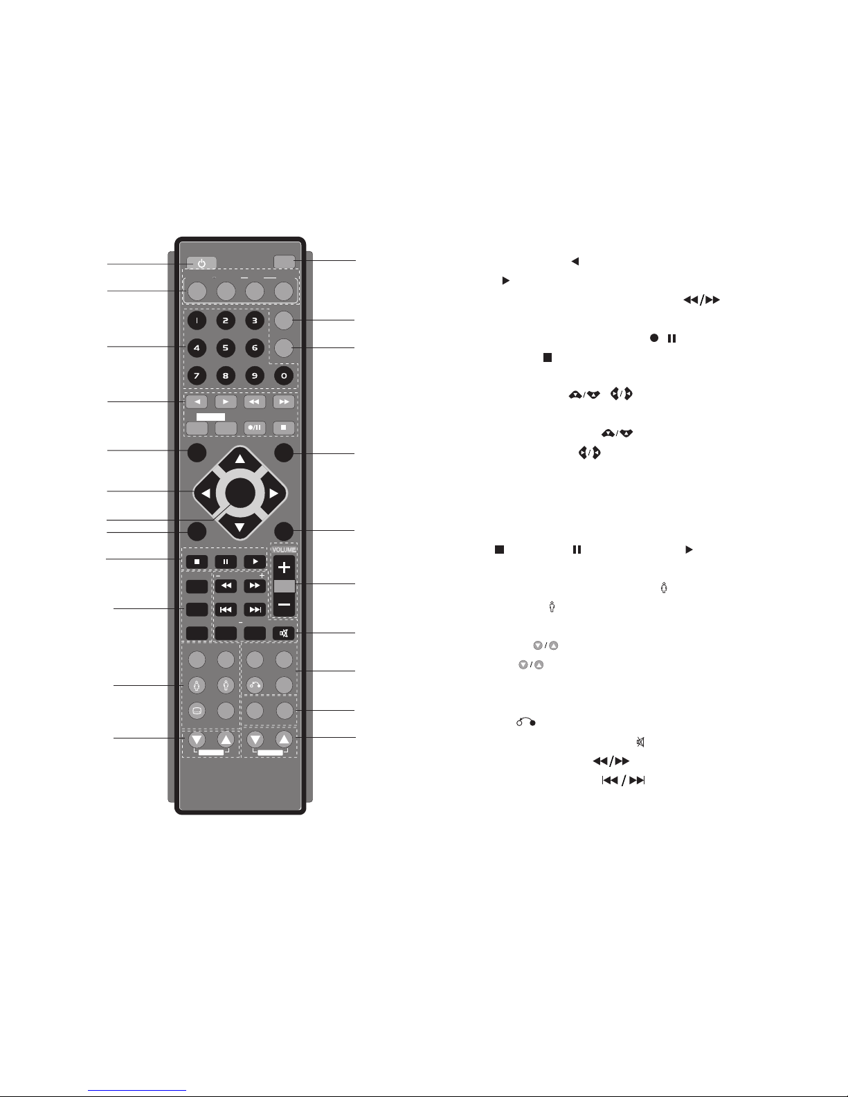
LOCATION OF USERS CONTROLS.........................1-5
SPECIFICATIONS ........................................................1-7
SECTION 2
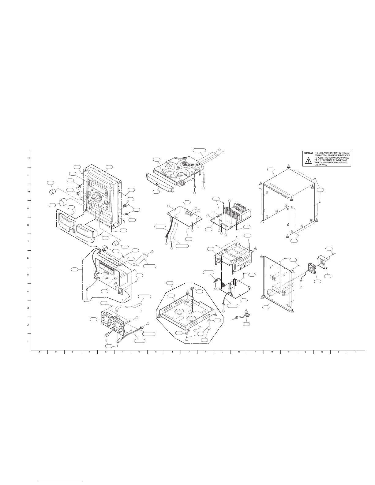
EXPLODED VIEWS
CABINET AND MAIN FRAME SECTION..................2-1
TAPE DECK MECHANISM EXPLODED VIEW ........2-3
1. TAPE DECK MECHANISM
(A/R & A/S : RIGHT A/R DECK)........................2-3
2. TAPE DECK MECHANISM
(A/R & A/S : LEFT A/S DECK) ..........................2-5
DVD MECHANISM EXPLODED VIEW ......................2-7
SPEAKER EXPLODED VIEW ....................................2-9
MODEL : MDS262V (FRONT SPEAKERS)...........2-9
PACKING ACCESSORY VIEW.................................2-13
SECTION 3
AUDIO PART ELECTRICAL
AUDIO ELECTRICAL
TROUBLESHOOTING GUIDE....................................3-1
1. POWER (SMPS) ................................................3-1
2. P-SENS...............................................................3-2
3. VKK CHECK.......................................................3-2
4. MICOM PART CHECK I ....................................3-2
5. MICOM PART CHECK II ...................................3-3
6. IC103(KS4CD21CS) CHECK............................3-4
7. FLD DISPLAY CHECK ......................................3-5
8. PWM MODULATION PART CHECK................3-6
9. POWER AMP PART CHECK............................3-7
10. AUX FUNCTION CHECK ..................................3-8
11. TUNER FUNCTION CHECK.............................3-9
12. TAPE FUNCTION CHECK ..............................3-10
13. TAPE PLAY PART CHECK..............................3-11
14. TAPE REC PART CHECK...............................3-12
INTERNAL BLOCK DIAGRAM OF ICs...................3-13
1. ES6838 ..............................................................3-13
2. HA12237F..........................................................3-14
3. PS9829B............................................................3-15
4. PT6324...............................................................3-15
5. STR-S6757IF1905 ............................................3-16
6. TAS5142.............................................................3-17
7. U1739EJ2V1UD00/KF2_E ...............................3-18
WIRING DIAGRAM ....................................................3-20
BLOCK DIAGRAM.....................................................3-22
1. SMPS BLOCK DIAGRAM...............................3-22
2. MAIN & FRONT BLOCK DIAGRAM ..............3-24
SCHEMATIC DIAGRAMS .........................................3-26
1. SMPS SCHEMATIC DIAGRAM.......................3-26
2. MAIN SCHEMATIC DIAGRAM ........................3-28
3. AMP SCHEMATIC DIAGRAM..........................3-30
4. DECK SCHEMATIC DIAGRAM .......................3-32
5. FRONT SCHEMATIC DIAGRAM.....................3-34
PRINTED CIRCUIT DIAGRAMS...............................3-36
1. MAIN P.C.BOARD............................................3-36
2. SMPS P.C.BOARD ..........................................3-40
3. FRONT P.C.BOARD ........................................3-42
SECTION 4
DVD PART ELECTRICAL
DVD ELECTRICAL
TROUBLESHOOTING GUIDE....................................4-1
1. POWER CHECK GUIDE...................................4-1
2. TEST & DEBUG FLOW.....................................4-2
3. USB PART ..........................................................4-7
WAVEFORMS ...............................................................4-8
1. WHEN POWER ON,
RESET & DATA ETC WAVEFORM ...................4-8
2.
OPEN / CLOSE WAVEFORM AT POWER ON
.......4-9
3.
STARTING ACTION WAVEFORM IN MD DEVICE
......4-9
4. FOCUS WAVEFORM (AT CD).........................4-10
5. FOCUS WAVEFORM (AT DVD) ......................4-10
6.
AT POWER ON, SPINDLE SIGNAL AT MD DECK
........4-11
7.
AT FIRST ACTION, FOCUS SIGNAL A, B, C, D
....4-11
8. TRACKING SIGNAL..........................................4-12
9. RF WAVEFORM ................................................4-12
10. DISK TYPE JUGEMENT WAVEFORM...........4-13
SCHEMATIC DIAGRAMS .........................................4-15
1. MPEG SCHEMATIC DIAGRAM .....................4-15
2. SERVO SCHEMATIC DIAGRAM ...................4-17
3. INTERFACE SCHEMATIC DIAGRAM ...........4-19
PRINTED CIRCUIT DIAGRAM .................................4-21
DVD P.C.BOARD .................................................4-21
SECTION 5
REPLACEMENT PARTS LIST
........5-1