LG 19LG30 Series User manual

EUT Type: LCD TV/Monitor
FCC ID: BEJ19LG30UA
Test Report No.: GETEC-E3-07-096
FCC Class B Certification
APPENDIX H
: USER’S MANUAL

Please read this manual carefully before operating
your set.
Retain it for future reference.
Record model number and serial number of the set.
See the label attached on the back cover and quote
this information to your dealer
when you require service.
LCD TV
OWNER’S MANUAL
LCD TV MODELS
19 LG 30
22LG30
P/NO : SAC30708022 (0712-REV00)
www.lgusa.com / www.lg.ca
As an ENERGY STAR
Partner LGE U. S. A.,Inc.
has determined that this
product meets the
ENERGY STAR guidelines
for energy efficiency.
ENERGY STAR is a set of power-saving
guidelines issued by the U.S.
Environmental Protection Agency(EPA).

1
WARNING / CAUTION
WARNING / CAUTION
To prevent fire or shock hazards, do not expose
this product to rain or moisture.
FCC NOTICE
Class B digital device
This equipment has been tested and found to comply
with the limits for a Class B digital device, pursuant to
Part 15 of the FCC Rules. These limits are designed
to provide reasonable protection against harmful
interference in a residential installation. This equipment
generates, uses and can radiate radio frequency energy
and, if not installed and used in accordance with the
instructions, may cause harmful interference to radio
communications. However, there is no guarantee that
interference will not occur in a particular installation.
If this equipment does cause harmful interference to
radio or television reception, which can be determined
by turning the equipment off and on, the user is
encouraged to try to correct the interference by one
or more of the following measures:
- Reorient or relocate the receiving antenna.
- Increase the separation between the equipment and
receiver.
- Connect the equipment to an outlet on a circuit
different from that to which the receiver is connected.
- Consult the dealer or an experienced radio/TV
technician for help.
Any changes or modifications not expressly approved
by the party responsible for compliance could void
the user’s authority to operate the equipment.
CAUTION
Do not attempt to modify this product in any way
without written authorization from LG Electronics.
Unauthorized modification could void the user’s
authority to operate this product
The lightning flash with arrowhead
symbol, within an equilateral triangle, is
intended to alert the user to the presence
of uninsulated “dangerous voltage” within the
product’s enclosure that may be of sufficient
magnitude to constitute a risk of electric shock to
persons.
The exclamation point within an equilateral
triangle is intended to alert the user to
the presence of important operating and
maintenance (servicing) instructions in the litera-
ture accompanying the appliance.
TO REDUCE THE RISK OF ELECTRIC SHOCK
DO NOT REMOVE COVER (OR BACK). NO
USER SERVICEABLE PARTS INSIDE. REFER TO
QUALIFIED SERVICE PERSONNEL.
WARNING/CAUTION
TO REDUCE THE RISK OF FIRE AND ELECTRIC
SHOCK, DO NOT EXPOSE THIS PRODUCT TO
RAIN OR MOISTURE.
NOTE TO CABLE/TV INSTALLER
This reminder is provided to call the CATV system
installer’s attention to Article 820-40 of the National
Electric Code (U.S.A.). The code provides guidelines for
proper grounding and, in particular, specifies that the
cable ground shall be connected to the grounding system
of the building, as close to the point of the cable entry
as practical.

2
IMPORTANT SAFETY INSTRUCTIONS
SAFETY INSTRUCTIONS
Important safety instructions shall be provided with each apparatus. This information shall be given in a separate
booklet or sheet, or be located before any operating instructions in an instruction for installation for use and
supplied with the apparatus.
This information shall be given in a language acceptable to the country where the apparatus is intended to be used.
The important safety instructions shall be entitled “Important Safety Instructions”. The following safety
instructions shall be included where applicable, and, when used, shall be verbatim as follows. Additional safety
information may be included by adding statements after the end of the following safety instruction list. At the
manufacturer’s option, a picture or drawing that illustrates the intent of a specific safety instruction may be
placed immediately adjacent to that safety instruction:
Read these instructions.
Keep these instructions.
Heed all warnings.
Follow all instructions.
Do not use this apparatus near water.
Clean only with dry cloth.
Do not block any ventilation openings. Install in
accordance with the manufacturer’s instructions.
Do not install near any heat sources such as
radiators, heat registers, stoves, or other apparatus
(including amplifiers)that produce heat.
When mounting a TV it on the wall, make sure
not to install TV by hanging power and signal
cables on the back of the TV.
Do not defeat the safety purpose of the polarized
or grounding-type plug. A polarized plug has
two blades with one wider than the other. A
grounding type plug has two blades and a third
grounding prong, The wide blade or the third
prong are provided for your safety. If the provided
plug does not fit into your outlet, consult an
electrician for replacement of the obsolete outlet.
Protect the power cord from being walked on
or pinched particularly at plugs, convenience
receptacles, and the point where they exit from
the apparatus.
Only use attachments/accessories specified by
the manufacturer.
Unplug this apparatus when unused for long
periods of time.
1
2
3
4
5
6
7
8
9

3
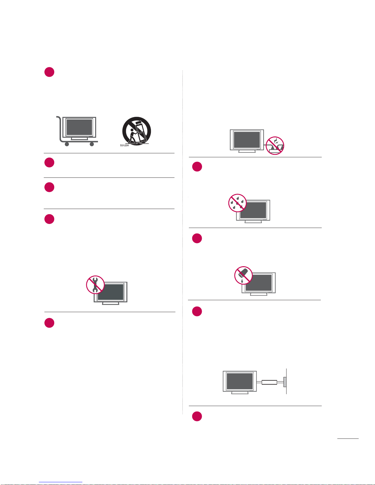
Use only with the cart, stand, tripod, bracket,
or table specified by the manufacturer, or sold
with the apparatus. When a cart is used, use
caution when moving the cart/apparatus
combination to avoid injury from tip-over.
Never touch this apparatus or antenna during
a thunder or lighting storm.
Do not allow a impact shock or any objects to
fall into the product, and do not drop onto the
screen with something.
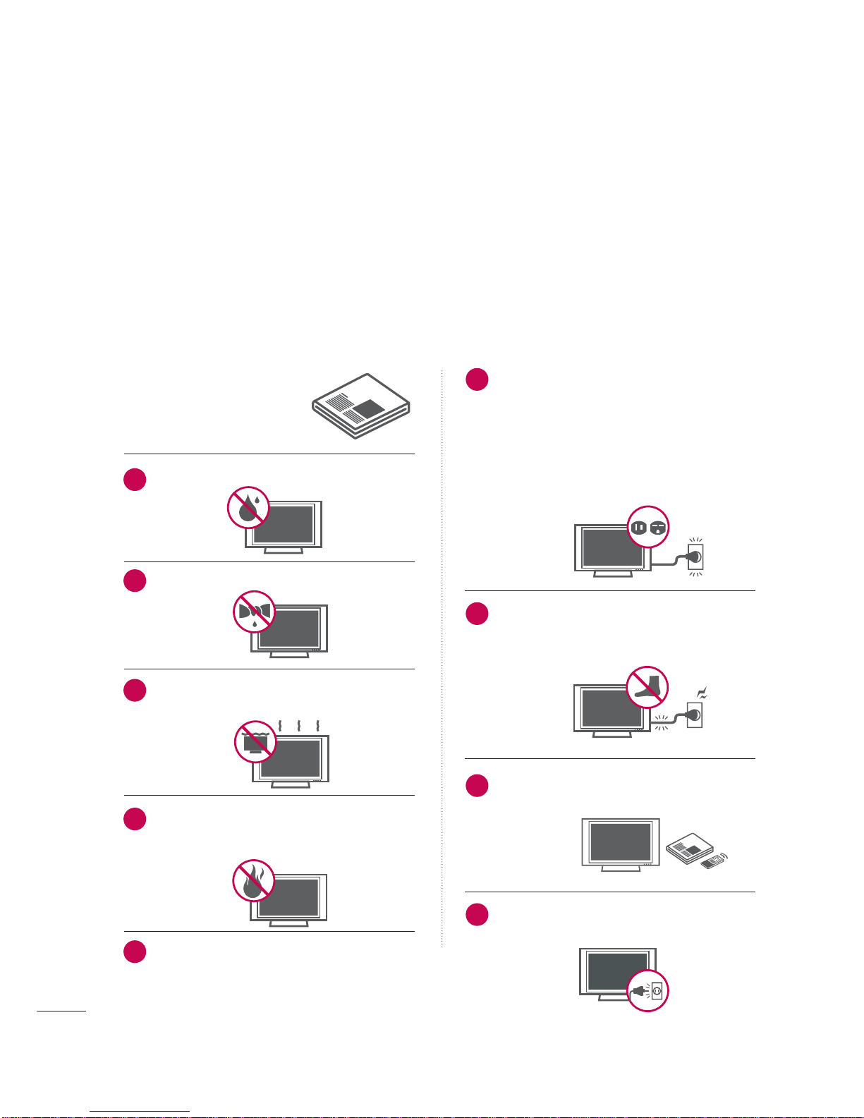
Refer all servicing to qualified service personnel.
Servicing is required when the apparatus has
been damaged in any way, such as power-supply
cord or plug is damaged, liquid has been
spilled or objects have fallen into the apparatus,
the apparatus has exposed to rain or moisture,
does not operate normally, or has been
dropped.
CAUTION concerning the Power Cord :
Most appliances recommend they be placed
upon a dedicated circuit; that is, a single outlet
circuit which powers only that appliance and
has no additional outlets or branch circuits.
Check the specification page of this owner's
manual to be certain.
Do not overload wall outlets. Overloaded wall
outlets, loose or damaged wall outlets, extension
cords, frayed power cords, or damaged or
cracked wire insulation are dangerous. Any of
these conditions could result in electric shock
or fire. Periodically examine the cord of your
appliance, and if its appearance indicates dam-
age or deterioration, unplug it, discontinue use
of the appliance, and have the cord replaced
with an exact replacement part by an authorized
servicer. Protect the power cord from physical
or mechanical abuse, such as being twisted,
kinked, pinched, closed in a door, or walked
upon. Pay particular attention to plugs, wall
outlets, and the point where the cord exits the
appliance.
Outdoor use marking :
WARNING - To reduce the risk of fire or elec-
tric shock, do not expose this appliance to rain
or moisture.
Wet Location Marking : Apparatus shall not be
exposed to dripping or splashing and no
objects filled with liquids, such as vases, shall
be placed on or over apparatus.
GROUNDING
Ensure that you connect the earth ground wire
to prevent possible electric shock. If grounding
methods are not possible, have a qualified
electrician install a separate circuit breaker.
Do not try to ground the unit by connecting it
to telephone wires, lightening rods, or gas pipes.
DISCONNECTING DDEVICE FFROM MMAINS
Mains plug is the disconnecting device. The
plug must remain readily operable.
12
10
11
14
13
15
16
17
18
Power
Supply
Short-circuit
Breaker

4
CONTENTS
WARNING / CAUTION
. . . . . . . . . . . . . . . . . . . . . . . . . . . . 1
SAFETY INSTRUCTIONS
. . . . . . . . . . . . . . . . . . . . . . . . . . 2
PREPARATION
Accessories . . . . . . . . . . . . . . . . . . . . . . . . . . . . . . . . . . . . . . . . . . . . . . . . . . . . . . 7
Front Panel Information . . . . . . . . . . . . . . . . . . . . . . . . . . . . . . . . . . . . . 8
Back Panel Information . . . . . . . . . . . . . . . . . . . . . . . . . . . . . . . . . . . . . . 9
Stand Installation . . . . . . . . . . . . . . . . . . . . . . . . . . . . . . . . . . . . . . . . . . . . 10
Back Cover for Wire Arrangement . . . . . . . . . . . . . . . . . . . . . 11
VESA Wall Mounting . . . . . . . . . . . . . . . . . . . . . . . . . . . . . . . . . . . . . . . . 12
Desktop Pedestal Installation . . . . . . . . . . . . . . . . . . . . . . . . . . . . 12
Positioning your Display . . . . . . . . . . . . . . . . . . . . . . . . . . . . . . . . . . . 13
Kensington Security System . . . . . . . . . . . . . . . . . . . . . . . . . . . . . 14
Antenna or Cable Connection . . . . . . . . . . . . . . . . . . . . . . . . . . 15
EXTERNAL EQUIPMENT SETUP
HD Receiver Setup . . . . . . . . . . . . . . . . . . . . . . . . . . . . . . . . . . . . . . . . . 16
DVD Setup . . . . . . . . . . . . . . . . . . . . . . . . . . . . . . . . . . . . . . . . . . . . . . . . . . . . . . 18
VCR Setup . . . . . . . . . . . . . . . . . . . . . . . . . . . . . . . . . . . . . . . . . . . . . . . . . . . . . 21
Pheadphone Setup . . . . . . . . . . . . . . . . . . . . . . . . . . . . . . . . . . . . . . . . . . 23
PC Setup . . . . . . . . . . . . . . . . . . . . . . . . . . . . . . . . . . . . . . . . . . . . . . . . . . . . . . . . 24
WATCHING TV / CHANNEL CONTROL
Remote Control Functions . . . . . . . . . . . . . . . . . . . . . . . . . . . . . . . 30
Turning On TV . . . . . . . . . . . . . . . . . . . . . . . . . . . . . . . . . . . . . . . . . . . . . . . . 32
Channel Selection . . . . . . . . . . . . . . . . . . . . . . . . . . . . . . . . . . . . . . . . . . . 32
Volume Adjustment . . . . . . . . . . . . . . . . . . . . . . . . . . . . . . . . . . . . . . . . . 32
Quick Menu . . . . . . . . . . . . . . . . . . . . . . . . . . . . . . . . . . . . . . . . . . . . . . . . . . . . 33
Initial Setting . . . . . . . . . . . . . . . . . . . . . . . . . . . . . . . . . . . . . . . . . . . . . . . . . . 34
On-Screen Menus Selection . . . . . . . . . . . . . . . . . . . . . . . . . . . . 36
Channel Setup
- Auto Scan (Auto Tuning) . . . . . . . . . . . . . . . . . . . . . . . . . . . 37
- Add / Delete Channel (Manual Tuning) . . . . . . 38
- Channel Editing . . . . . . . . . . . . . . . . . . . . . . . . . . . . . . . . . . . . . . . . 39
Input List . . . . . . . . . . . . . . . . . . . . . . . . . . . . . . . . . . . . . . . . . . . . . . . . . . . . . . . . 40
Input Label . . . . . . . . . . . . . . . . . . . . . . . . . . . . . . . . . . . . . . . . . . . . . . . . . . . . . . 41
AV Mode . . . . . . . . . . . . . . . . . . . . . . . . . . . . . . . . . . . . . . . . . . . . . . . . . . . . . . . . 42
PICTURE CONTROL
Picture Size (Aspect Ratio) Control . . . . . . . . . . . . . . . . . . 43
Preset Picture Settings
- Picture Mode - Preset . . . . . . . . . . . . . . . . . . . . . . . . . . . . . . . 44
- Color Tone - Preset . . . . . . . . . . . . . . . . . . . . . . . . . . . . . . . . . . . 45
Manual Picture Adjustment
- Picture Mode - User Mode . . . . . . . . . . . . . . . . . . . . . . . . 46
- Color Tone - User Mode . . . . . . . . . . . . . . . . . . . . . . . . . . . 47
Picture Improvement Technology . . . . . . . . . . . . . . . . . . . . . 48
Advanced - Black (Darkness) Level . . . . . . . . . . . . . . . . . . . 49
Advanced - Film Mode . . . . . . . . . . . . . . . . . . . . . . . . . . . . . . . . . . . . . 50
Picture Reset . . . . . . . . . . . . . . . . . . . . . . . . . . . . . . . . . . . . . . . . . . . . . . . . . . 51
SOUND & LANGUAGE CONTROL
Clear Voice . . . . . . . . . . . . . . . . . . . . . . . . . . . . . . . . . . . . . . . . . . . . . . . . . . . . . 52
Preset Sound Setting (Sound Mode) . . . . . . . . . . . . . . . . 53
Sound Setting Adjustment - User Mode . . . . . . . . . . . 54
Balance . . . . . . . . . . . . . . . . . . . . . . . . . . . . . . . . . . . . . . . . . . . . . . . . . . . . . . . . . . . 55
Audio Reset . . . . . . . . . . . . . . . . . . . . . . . . . . . . . . . . . . . . . . . . . . . . . . . . . . . 56
Stereo/SAP Broadcasts Setup . . . . . . . . . . . . . . . . . . . . . . . . . . 57
Audio Language . . . . . . . . . . . . . . . . . . . . . . . . . . . . . . . . . . . . . . . . . . . . . . 58
On-Screen Menus Language Selection . . . . . . . . . . . . . . 59
Caption Mode
- Analog Broadcasting System Captions . . . . . . . 60
- Digital Broadcasting System Captions . . . . . . . . 61
- Caption Option . . . . . . . . . . . . . . . . . . . . . . . . . . . . . . . . . . . . . . . 62

5
TIME SETTING
Clock Setting
- Auto Clock Setup . . . . . . . . . . . . . . . . . . . . . . . . . . . . . . . . . . . . 63
- Manual Clock Setup . . . . . . . . . . . . . . . . . . . . . . . . . . . . . . . . . 64
Auto On/Off Timer Setting . . . . . . . . . . . . . . . . . . . . . . . . . . . . . 65
Sleep Timer Setting . . . . . . . . . . . . . . . . . . . . . . . . . . . . . . . . . . . . . . . . . 66
Auto Shut-off Setting . . . . . . . . . . . . . . . . . . . . . . . . . . . . . . . . . . . . . . . 67
PARENTAL CONTROL / RATINGS
Set Password & Lock System . . . . . . . . . . . . . . . . . . . . . . . . . . . 68
Channel Blocking . . . . . . . . . . . . . . . . . . . . . . . . . . . . . . . . . . . . . . . . . . . . 71
Movie & TV Rating . . . . . . . . . . . . . . . . . . . . . . . . . . . . . . . . . . . . . . . . . . 72
Downloadable Rating . . . . . . . . . . . . . . . . . . . . . . . . . . . . . . . . . . . . . . 77
External Input Blocking . . . . . . . . . . . . . . . . . . . . . . . . . . . . . . . . . . . . 78
Key lock . . . . . . . . . . . . . . . . . . . . . . . . . . . . . . . . . . . . . . . . . . . . . . . . . . . . . . . . . 79
APPENDIX
Troubleshooting . . . . . . . . . . . . . . . . . . . . . . . . . . . . . . . . . . . . . . . . . . . . . . 80
Maintenance . . . . . . . . . . . . . . . . . . . . . . . . . . . . . . . . . . . . . . . . . . . . . . . . . . . 82
Product Specifications . . . . . . . . . . . . . . . . . . . . . . . . . . . . . . . . . . . . . 83
External Control Through RS-232C . . . . . . . . . . . . . . . . . .84

6
■
If the TV feels cold to the touch, there may be a small “flicker” when it is turned on. This is normal, there is
nothing wrong with TV.
■
Some minute dot defects may be visible on the screen, appearing as tiny red, green, or blue spots. However, they
have no adverse effect on the monitor's performance.
■
Avoid touching the LCD screen or holding your finger(s) against it for long periods of time. Doing so may produce
some temporary distortion effects on the screen.
On Disposal
a. The fluorescent lamp used in this product contains a small amount of mercury.
b. Do not dispose of this product with general household waste.
c. Disposal of this product must be carried out in accordance to the regulations of your local authority.

PREPARATION
7
PREPARATION
ACCESSORIES
Ensure that the following accessories are included with your product. If an accessory is missing, please contact
the dealer where you purchased the product.
User must use shielded signal interface cables (D-sub 15 pin cable) with ferrite cores to maintain standard
compliance for the product.
The accessories can be different from the figures shown here.
Option EExtras
D-sub 15 pin Cable
Cable Management Clip
* Slightly wipe stained spot on the exterior only with the polishing
cloth for the product exterior if there is stain or fingerprint on
surface of the exterior.
* Do not wipe roughly when removing stain. Please be cautions of
that excessive pressure may cause scratch or discoloration.
Polishing Cloth
Copyright©2007 LGE,
AllRights Reserved.
1.5V 1.5V
Owner’s Manual Power Cord 75ohm Round Cable
Remote Control,
Batteries
123
456
78
0-
9
VOLCH
ENTER
POWER
MUTE
Q.MENU
MENU
FLASHBK
EXIT
CC
AVMODE
FAV
PICTURESOUND
RATIO
TV
INPUT
CD Manual

PREPARATION
8
FRONT PANEL INFORMATION
PREPARATION
■
Image shown may differ from your TV
■
NOTE: If your product has a protection tape attached, remove the tape.
And then wipe the product with a cloth (If a polishing cloth is included with your product, use it).
INPUT MENU VOL CH
ENTER
CHANNEL
(EE,D)Buttons
VOLUME
(F,G)Buttons
MENU
Button
ENTER
Button
INPUT
Button
Remote Control Sensor
POWER Button
Power/Standby Indicator
Illuminates red in standby mode.
Illuminates blue when the set is switched on.

PREPARATION
9
BACK PANEL INFORMATION
■
Image shown may differ from your TV
HDMI/DVI IN
Connect a HDMI signal to this jack.
Or DVI (Video) signal to this jack with a HDMI to
DVI cable.
RGB (PC) IN
Connect the output from a PC.
AUDIO (RGB/DVI) IN
Connect the audio from a PC.
ANTENNA/CABLE IN
Connect over-the air signals to this jack.
Connect cable signals to this jack.
AV IN (Audio/Video)
Connect audio/video output from an external
device to these jacks.
S-VIDEO
Connect S-Video out from an S-VIDEO device.
COMPONENT IN
Connect a component video/audio device to
these jacks.
RS-232C IN (CONTROL & SERVICE) PORT
Connect to the RS-232C port on a PC.
SERVICE ONLY
For service.
HEADPHONE INPUT
Plug the headphone into the headphone socket.
Power Cord Socket
For operation with AC power.
Caution: Never attempt to operate the TV on DC
power.
1
2
3
4
5
6
7
8
9
COMPONENT IN
ANTENNA/CABLE IN
RS-232C IN
(CONTROL & SERVICE)
AUDIO IN
(RGB/DVI)
RGB(PC) IN
AV IN
VIDEO
AUDIO
HDMI/DVI IN
VIDEO
L(MONO)
R
L R
AUDIO
S-VIDEO
SERVICE
ONLY
21
3
8
67
9
4
5

PREPARATION
10
PREPARATION
STAND INSTALLATION
Carefully place the TV screen side down on a cush-
ioned surface to protect the screen from damage.
Assemble the TV as shown.
1
2
Fix the 4 bolts securely using the holes in the
back of the TV
3
■
Image shown may differ from your TV

PREPARATION
11
BACK COVER FOR WIRE ARRANGEMENT
■
Image shown may differ from your TV
Connect the cables as necessary.
To connect an additional equipment, see the
EXTERNAL EQUIPMENT SETUP section.
Install the CABLE MANAGEMENT CLIP as
shown and manage the cable.
CABLE MANAGEMENT CLIP
1
2
Fit the CABLE MANAGEMENT CLIP as shown.
3

PREPARATION
12
VESA WALL MOUNTING
PREPARATION
For proper ventilation, allow a clearance of 4 inches on all four sides from the wall.
DESKTOP PEDESTAL INSTALLATION
This product accepts a VESA-compliant mounting interface pad. (optional)
There 4 threaded holes are available for attaching the bracket.
GScrew length needed depends on the wall mount used. For further information, refer to the VESA
Wall Mounting Instruction Guide.
NOTE
!
100 mm
100 mm
GEnsure adequate ventilation by following the clearance recommendations.
CAUTION
4 inches
4 inches
4 inches 4 inches

PREPARATION
13
POSITIONING YOUR DISPLAY
■
Here shown may be somewhat different from your TV.
■
Adjust the position of the panel in various ways for maximum comfort.
• Tilt range
10
0
3
0

PREPARATION
14
KENSINGTON SECURITY SYSTEM
PREPARATION
- The TV is equipped with a Kensington Security System connector on the back panel. Connect the
Kensington Security System cable as shown below.
- For the detailed installation and use of the Kensington Security System, refer to the user’s guide provided
with the Kensington Security System.
For further information, contact h
http://www.kensington.com, the internet homepage of the
Kensington company. Kensington sells security systems for expensive electronic equipment such as note-
book PCs and LCD projectors.
NOTE
- The Kensington Security System is an optional accessory.

PREPARATION
15
ANTENNA OR CABLE CONNECTION
1. Antenna (Analog or Digital)
Wall Antenna Socket or Outdoor Antenna without a Cable Box
Connections.
For optimum picture quality, adjust antenna direction if needed.
2. Cable
Wall
Antenna
Socket
Outdoor
Antenna
(VHF, UHF)
Cable TV
Wall Jack
Multi-family Dwellings/Apartments
(Connect to wall antenna socket)
RF Coaxial Wire (75 ohm)
Single-family Dwellings /Houses
(Connect to wall jack for outdoor antenna)
Be careful not to bend the bronze wire
when connecting the antenna.
Copper Wire
GThe TV will let you know when the analog, cable, and digital channel scans are complete.
NOTE
!
■To improve the picture quality in a poor signal area, please purchase a signal amplifier and install properly.
■If the antenna needs to be split for two TV’s, install a 2-Way Signal Splitter.
■If the antenna is not installed properly, contact your dealer for assistance.
Antenna
UHF
Signal
Amplifier
VHF
ANTENNA/CABLE IN
ANTENNA/CABLE IN
ANTENNA/CABLE IN
■
Image shown may differ from your TV.

EXTERNAL EQUIPMENT SETUP
16
EXTERNAL EQUIPMENT SETUP
HD RECEIVER SETUP
This TV can receive Digital Over-the-air/Cable signals without an external digital set-top box. However, if you do
receive digital signals from a digital set-top box or other digital external device, refer to the figure as shown below.
When connecting Component cable
1. How to connect
Connect the video outputs (Y, PB, PR)of the digital set
top box to the COMPONENT IINVVIDEO jacks on
the set. Match the jack colors (Y = green, PB= blue, and
PR= red).
Connect the audio output of the digital set-top box to
the COMPONENT IINAAUDIO jacks on the set.
2
1
2. How to use
■Turn on the digital set-top box.
(Refer to the owner’s manual for the digital set-top box.
operation)
■Select Component input source by using the INPUT
button on the remote control.
■To prevent the equipment damage, never plug in any power cords until you have finished connecting all equipment.
ANTENNA/CABLE IN
IN
RVICE)
AUDIO IN
(RGB/DVI)
IN
AV IN
VIDEO
L(MONO)
R
AUDIO
S-VIDEO
VIDEO
AUDIO
L R
COMPONENT IN
Y L RPBPR
12
Y, CB/PB, CR/PR
Horizontal Vertical
Frequency(KHz)Frequency(Hz)
15.73 59.94
15.73 60.00
31.47 59.94
31.50 60.00
44.96 59.94
45.00 60.00
33.72 59.94
33.75 60.00
27.00 24.00
33.75 30.00
67.43 59.94
67.50 60.00
Resolution
720x480i
720x480p
1280x720p
1920x1080i
1920x1080p
Signal
480i
480p
720p
108 0 i
108 0 p
Component
Yes
Yes
Yes
Yes
Yes
HDMI
No
Yes
Yes
Yes
Yes

EXTERNAL EQUIPMENT SETUP
17
RS-232C IN
(CONTROL & SERVICE)
A
(R
RGB(PC) IN
SERVICE
ONLY
HDMI/DVI IN
HDMI-DTV OUTPUT
When connecting HDMI cable
Connect the digital set-top box to HDMI/DVI IIN
jack on the set.
No separated audio connection is necessary.
HDMI supports both audio and video.
1. How to connect
2. How to use
■Turn on the digital set-top box.
(Refer to the owner’s manual for the digital set-top box.)
■Select HDMI input source with using the INPUT button
on the remote control.
2
1
1
HDMI-DTV
Horizontal Vertical
Frequency(KHz)Frequency(Hz)
31.47 59.94
31.50 60.00
44.96 59.94
45.00 60.00
33.72 59.94
33.75 60.00
27.00 24.00
33.75 30.00
67.43 59.94
67.50 60.00
Resolution
720x480p
1280x720p
1920x1080i
1920x1080p

EXTERNAL EQUIPMENT SETUP
18
EXTERNAL EQUIPMENT SETUP
When connecting HDMI to DVI cable
1. How to connect
Connect the DVI output of the digital set-top box to the
HDMI/DVI IINjack on the set.
Connect the audio output of the digital set-top box to
the AUDIO IIN(RGB/DVI)jack on the set.
2
1
2. How to use
■Turn on the digital set-top box. (Refer to the owner’s manual
for the digital set-top box.)
■Select HDMI input source with using the INPUT button on
the remote control.
COMPONENT IN
RS-232C IN
(CONTROL & SERVICE)
AUDIO IN
(RGB/DVI)
RGB(PC) IN
VIDE
S-VID
SERVICE
ONLY
HDMI/DVI IN
L R
DVI-DTV OUTPUT
12
Other manuals for 19LG30 Series
3
This manual suits for next models
1
Table of contents
Other LG LCD TV manuals