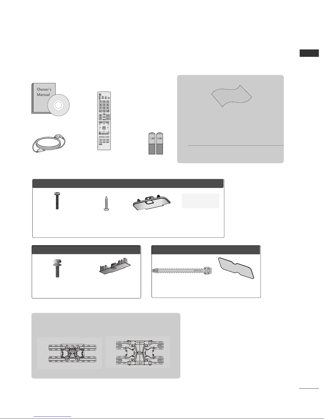
LG 26LK311 User manual

www.lg.com
OWNER’S MANUAL
LCD TV
Please read this manual carefully before operating
your set and retain it for future reference.

HDMI, the HDMI logo and High Definition
Multimedia Interface are trademarks or registered
trademarks of HDMI Licensing LLC.

1
ACCESSORIES
ACCESSORIES
Bolts for stand assembly
(Refer to p. 11)
x 4
Protect on cover
(Refer to p. 12)
Ensure that the following accessories are included with your TV.
If an accessory is missing, please contact the dealer where you purchased the TV.
■
Image shown may differ from your TV.
Owner’s Manual
Batter es (AAA)
Power Cord
Pol sh ng Cloth
Pol sh ng cloth for use on the screen.
Th s tem s not ncluded for all models.
* L ghtly w pe any sta ns or f ngerpr nts on
the surface of the TV w th the pol sh ng
cloth.
Do not use excess ve force. Th s may cause
scratch ng or d scolourat on.
Remote Control
OOnnllyy 2222LLKK33****
Protect on cover
(Refer to p. 12)
Cable Holder
(Refer to p. 13)
Bolts for stand
assembly
(Refer to p. 10)
OOnnllyy 2266//3322LLKK33****,, 3322//4422LLKK44****
Protect on cover
(Refer to p. 12)
x 8
M4 x 20
1-screw for
stand f x ng
(Refer to p. 11)
Wall Mount ng Bracket(Separate purchase)
OOnnllyy 1199//2222//2266//3322LLVV22******
LSW100B or
LSW100BG
(22/26/32LK3**, 32LK4**)
or
LSW200B or
LSW200BG
(42LK4**)
Home

CO TE TS
2
CO TE TS
ACCESSORIES
. . . . . . . . . . . . . . . . . . . . . . . . . . . . . . . . . . . . . . . . . . . .
1
PREPARATION
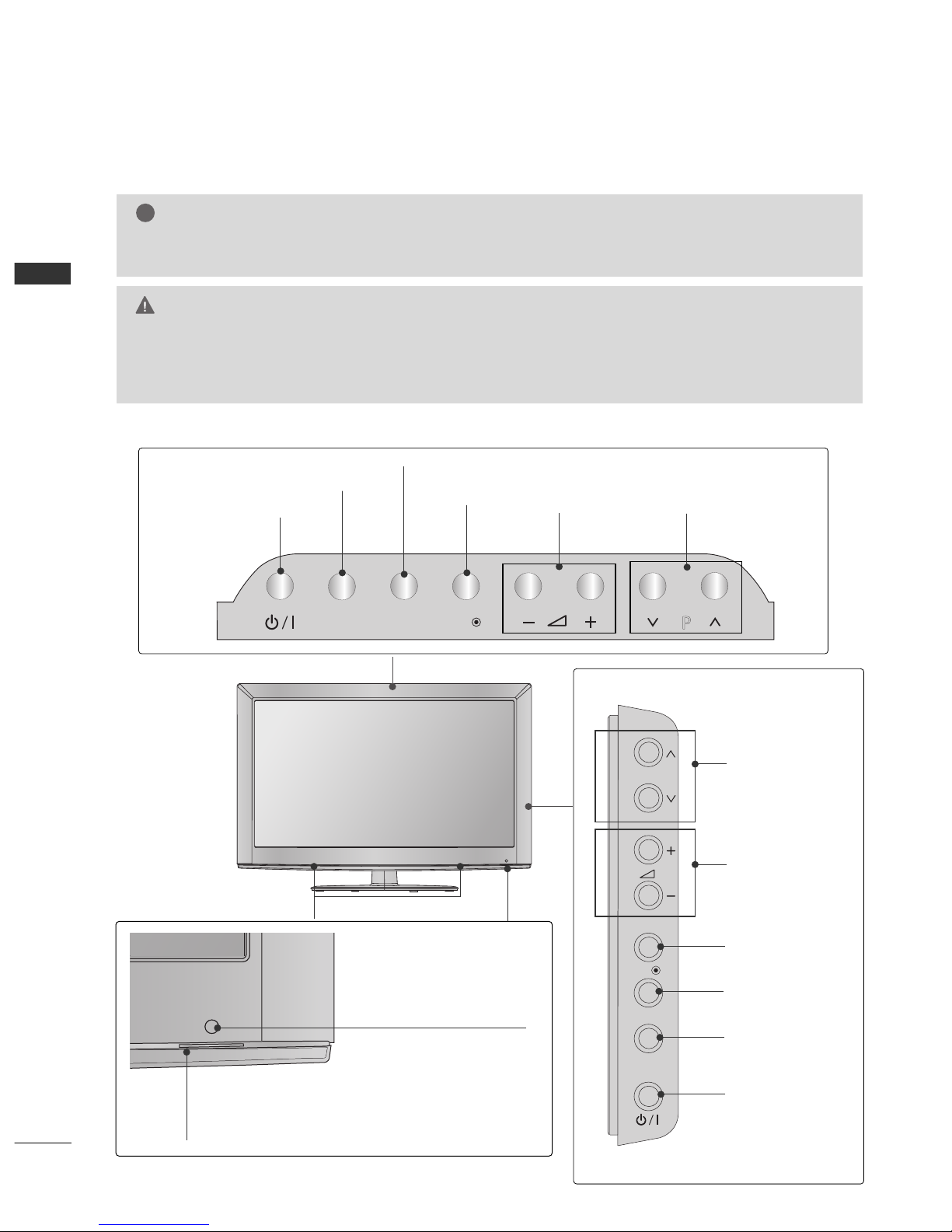
Front Panel Controls..................................................... 4
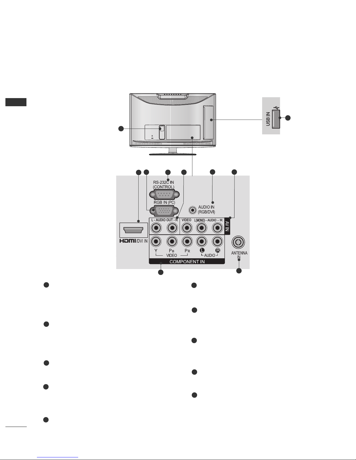
Back Panel Information ................................................ 6
Stand Installation......................................................... 10
Swivel Stand ................................................................. 11
Attaching the TV to a desk.........................................11
Positioning your Display ........................................... 11
Not Using the desk type stand.................................12
Back Cover for Wire Arrangement........................... 13
Careful Installation Advice......................................... 14
Desktop Pedestal Installation................................... 14
Wall Mount: Horizontal Installation........................ 15
Kensington Security System .................................... 15
Antenna Connection................................................... 16
EXTERNAL EQUIPMENT SETUP
HD Receiver Setup ...................................................... 17
DVD Setup .....................................................................20
VCR Setup......................................................................22
USB in Setup ............................................................... 23
Other A/V Source Setup........................................... 24
External Stereo Setup ................................................ 25
AV Output Setup ........................................................ 26
PC Setup........................................................................ 26
Screen Setup for PC Mode .............................. 28
WATCHING TV / PROGRAMME CONTROL
Remote Control Key Functions................................ 32
Turning on the TV....................................................... 36
Programme Selection ................................................ 36
Volume Adjustment .....................................................36
Quick Menu ................................................................. 37
On Screen Menus Selection and Adjustment..... 38
Auto Programme Tuning............................................ 39
Manual Programme Tuning ....................................... 40
Programme Edit............................................................ 42
Selecting the Programme List ...................................44
Favourite Programme Setup...................................... 45
Input List........................................................................ 46
Input Label .................................................................... 47
..................................................................48
Key Lock......................................................................... 50
Initializing(Reset to original factory settings)...... 51
AV Mode........................................................................ 52
TO USE A USB DEVICE
When connecting the USB device.......................... 53
Photo List ...................................................................... 55
Music List........................................................................59
Movie List........................................................................62
DivX Registration Code..............................................66
Deactivation...................................................................67
PICTURE CONTROL
Picture Size (Aspect Ratio) Control ...................... 68
Energy Saving ............................................................... 70
Preset Picture Settings
Picture Mode Preset............................................ 71
Manual Picture Adjustment
Picture Mode User option................................. 72
Picture Improvement Technology........................... 73
Expert Picture Control ................................................74
Picture Reset................................................................. 77
Power Indicator..............................................................78
Demo Mode.................................................................. 79
Mode Setting................................................................ 80

CO TE TS
3
SOUND & LANGUAGE CONTROL
Auto Volume Leveler ................................................... 81
Preset Sound Settings Sound Mode................... 82
Sound Setting Adjustment User Mode ...............83
Infinite Surround.......................................................... 84
Clear Voice ll................................................................. 85
Balance........................................................................... 86
TV Speakers On/ Off Setup..................................... 87
Audio Reset....................................................................88
I/II
Stereo/Dual Reception....................................... 89
NICAM Reception.............................................................. 90
Speaker Sound Output Selection.................... 90
On Screen Menu Language Selection ......................... 91
TIME SETTING
Clock Setup .................................................................. 92
Auto On/ Off Timer Setting..................................... 93
Sleep Timer Setting .................................................... 93
TELETEXT
Switch on/off ............................................................... 94
SIMPLE Text .................................................................. 94
TOP Text........................................................................ 94
FASTEXT........................................................................ 95
Special Teletext Functions......................................... 95
APPENDIX
Troubleshooting........................................................... 96
Maintenance ................................................................ 98
Product Specifications............................................... 99
IR Codes ...................................................................... 101
External Control Device Setup ...............................102

4
PREPARATIO
PREPARATIO
FRO T PA EL CO TROLS
■
Image shown may differ from your TV.
INPUT HOME
OK
P
P
OK
HOME
INPUT
PROGRAMME
VOLUME
OK
HOME
POWER
I PUT
Only 26/32LK3**
PROGRAMME
VOLUME
OK
HOME
I PUT
POWER
Only 22LK3**
Remote Control Sensor
Power/Standby Indicator
•
Can be adjusted using the Power Indicator in the
OPTIO menu.
G Do not step on the glass stand or subject it to any impact.
It may break, causing possible injury from fragments of glass, or the TV may fall.
G Do not drag the TV. The floor or the product may be damaged.
CAUTION
NOTE
!
G
The energy consumed during use can be significantly reduced if the level of brightness of the picture is
reduced, and this will reduce the overall running cost.
SPEAKER

5
PREPARATIO
OK
P
HOME
INPUT
PROGRAMME
VOLUME
OK
HOME
I PUT
POWER
Remote Control Sensor
■
Image shown may differ from your TV.
Only 32/42LK4**
SPEAKER
Power/Standby Indicator
•
Can be adjusted using the Power Indicator
in the OPTIO menu.

Power Cord Socket
This TV operates on an AC power. The voltage is
indicated on the Specifications page. Never
attempt to operate the TV on DC power.
HDMI Input
Connect a HDMI signal to HDMI IN.
Or DVI(VIDEO)signal to HDMI/DVI port with DVI
to HDMI cable.
RGB I Input
Connect the output from a PC.
RS-232C I PORT
Connect to the RS 232C port on a PC.
This port is used for Service or Hotel mode.
Audio output
Connect an external amplifier or add a subwoofer
to your surround sound system.
RGB/DVI Audio Input
Connect the audio from a PC.
Audio/Video Input
Connect audio/video output from an external
device to these jacks.
Component Input
Connect a component video/audio device to
these jacks.
Antenna Input
Connect RF antenna to this jack.
USB I Input
Connect USB storage device to this jack.
6
PREPARATIO
PREPARATIO
BACK PA EL I FORMATIO
■
Image shown may differ from your TV.
K
AC-IN
1
Only
22LK3**
2
89
36
7
4
10
1
2
3
4
5
6
7
8
9
10
5

Power Cord Socket
This TV operates on an AC power. The voltage is
indicated on the Specifications page. Never
attempt to operate the TV on DC power.
HDMI Input
Connect a HDMI signal to HDMI IN.
Or DVI(VIDEO)signal to HDMI/DVI port with DVI
to HDMI cable.
RGB I Input
Connect the output from a PC.
RS-232C I PORT
Connect to the RS 232C port on a PC.
This port is used for Service or Hotel mode.
Audio output
Connect an external amplifier or add a subwoofer
to your surround sound system.
RGB/DVI Audio Input
Connect the audio from a PC.
Audio/Video Input
Connect audio/video output from an external
device to these jacks.
Component Input
Connect a component video/audio device to
these jacks.
Antenna Input
Connect RF antenna to this jack.
USB I Input
Connect USB storage device to this jack.
7
PREPARATIO
■
Image shown may differ from your TV.
AC IN
CABLE MANAGEMENT
1
2
89
36
7
4
7
10
Only
26/32LK3**
5
1
2
3
4
5
6
7
8
9
10

RGB IN
(PC)
RS-232C IN
(CONTROL & SERVICE)
AUDIO IN
(RGB/DVI)
ANTENNA /
CABLE IN
/DVI IN
OPTICAL
DIGITAL
AUDIO OUT
VIDEOVIDEO
AUDIO
VIDEO
COMPONENT IN
AV IN 1
1
L/MONOL/MONO
AV IN 2
L/MONO
R
AUDIO
VIDEO
HDMI IN 3 USB IN
H/P
8
PREPARATIO
PREPARATIO
■
Image shown may differ from your TV.
1
Only
32/42LK4**
Power Cord Socket
This TV operates on an AC power. The voltage is
indicated on the Specifications page. Never
attempt to operate the TV on DC power.
HDMI Input
Connect a HDMI signal to HDMI IN.
Or DVI(VIDEO)signal to HDMI/DVI port with DVI
to HDMI cable.
RGB I Input
Connect the output from a PC.
RS-232C I PORT
Connect to the RS 232C port on a PC.
This port is used for Service or Hotel mode.
RGB/DVI Audio Input
Connect the audio from a PC.
Audio/Video Input
Connect audio/video output from an external
device to these jacks.
Component Input
Connect a component video/audio device to
these jacks.
Antenna Input
Connect RF antenna to this jack.
USB I Input
Connect USB storage device to this jack.
OPTICAL DIGITAL AUDIO OUT
Connect digital audio to various types of equip
ment.
Connect to a Digital Audio Component.
Use an Optical audio cable..
1
2
3
4
5
7
6
8
9
2
9
10
2
8
36
7
10 4
5

9
PREPARATIO
K
AC-IN
1
ANTENNA
IN
L/MONO
R
AUDIO
VIDEOL - AUDIO OUT - R
COMPONENT IN
AUDIO
VIDEO
ANTENNA
IN
L(L(MONO)MONO)
R
AUDIOAUDIO
VIDEOVIDEOL - AUDIO OUT - RL - AUDIO OUT - R
AV IN
AUDIO IN
(RGB/DVI)
RGB IN
(PC)
RS-232C IN
(CONTROL)
/DVI IN
2
89
36
7
4
10
Only
19/22LV2***
■
Image shown may differ from your TV.
AC IN
CABLE MANAGEMENT
1
COMPONENT IN
AUDIO
VIDEO
ANTENNA
IN
L/
L/
MONO
MONO
R
AUDIO
AUDIO
VIDEO
VIDEO
L - AUDIO OUT - R
L - AUDIO OUT - R
AV IN1
1
AUDIO IN
(RGB/DVI)
RGB IN
(PC)
RS-232C IN
(CONTROL)
ANTENNA
IN
L(MONO)
R
AUDIO
VIDEOL - AUDIO OUT - R
2
/DVI IN
2
89
36
7
4
7
10
Only
26/32LV2***
Power Cord Socket
This TV operates on an AC power. The voltage is
indicated on the Specifications page. Never
attempt to operate the TV on DC power.
HDMI Input
Connect a HDMI signal to HDMI IN.
Or DVI(VIDEO)signal to HDMI/DVI port with DVI
to HDMI cable.
RGB I Input
Connect the output from a PC.
RS-232C I PORT
Connect to the RS 232C port on a PC.
This port is used for Service or Hotel mode.
Audio output
Connect an external amplifier or add a subwoofer
to your surround sound system.
RGB/DVI Audio Input
Connect the audio from a PC.
Audio/Video Input
Connect audio/video output from an external
device to these jacks.
Component Input
Connect a component video/audio device to
these jacks.
Antenna Input
Connect RF antenna to this jack.
USB I Input
Connect USB storage device to this jack.
1
2
3
4
6
8
7
9
10
55
5

10
PREPARATIO
PREPARATIO
STA D I STALLATIO
■
Image shown may differ from your TV.
■
When assembling the desk type stand, check whether the bolt is fully tightened. (If not tightened fully, the
product can tilt forward after the product installation.) If you tighten the bolt with excessive force, the bolt can
deviate from abrasion of the tightening part of the bolt.
1Carefully place the TV screen side down on a cush
ioned surface to protect the screen from damage.
2Assemble the TV as shown.
Only 22LK3**
1
3
4
Carefully place the TV screen side down on a
cushioned surface to protect the screen from
damage.
2Assemble the parts of the SSttaanndd BBooddyywith
the SSttaanndd BBaasseeof the TV.
Assemble the TV as shown.
Fix the 4 bolts securely using the holes in the
back of the TV.
Stand Body
Stand Base
Only 26/32LK3**, 32/42LK4**
M4X20
M4X20

11
PREPARATIO
1
2
3
Carefully place the TV screen side down on a cushioned
surface to protect the screen from damage.
Assemble the TV as shown.
Fix the 4 bolts securely using the holes in the
back of the TV.
Only 19/22/26/LV2***
Only 26/32LK3**, 32/42LK4**
ATTACHI G THE TV TO A
DESK
■
Image shown may differ from your TV.
The TV must be attached to desk so it cannot be pulled
in a forward/backward direction, potentially causing
injury or damaging the product. Use only an attached
screw.
AC IN
CABLE MANAGEMENT
1 Screw (provided as parts of the product)
Desk
Stand
WARNING
!
G To prevent TV from falling over, the TV should
be securely attached to the floor/wall per installa-
tion instructions. Tipping, shaking, or rocking the
machine may cause injury.
SWIVEL STA D
(Except 22LK3**)
■
This feature is not available for all models.
■
After installing the TV, you can adjust the TV manually
to the left or right direction by 20 degrees to suit your
viewing position.
POSITIO I G YOUR DISPLAY
(Only 22LK3**)
■
Image shown may differ from your TV.
■
Adjust the position of the panel in various ways for
maximum comfort.
• Tilt range
12
03
0

12
PREPARATIO
PREPARATIO
Insert the PPrrootteeccttiioonn CCoovveerrinto the TV until
clicking sound.
■
Image shown may differ from your TV.
When installing the wall-mounted unit, use the protection cover.
OT USI G THE DESK-TYPE STA D
Loose the bolts from TV.
After removing the protection paper from the
protection cover, adhere it to the TV as shown.
Detach the SSttaanndd from TTVV.
2
3
4
Only 22LK3**
1Carefully place the TV screen side down on a cush
ioned surface to protect the screen from damage.
Protection Cover
Insert the PPrrootteeccttiioonn CCoovveerrinto the TV until clicking
sound.
PPrrootteeccttiioonn CCoovveerr
Only 26/32LK3**, 32/42LK4**
Only 19/22/26/32LV2***
PPrrootteeccttiioonn CCoovveerr

13
PREPARATIO
BACK COVER FOR WIRE ARRA GEME T
■
Image shown may differ from your TV.
Only 22LK3**
After Connecting the cables as necessary, install
CABLE HOLDER as shown and bundle the cables.
K
AC-IN
K
AC-IN
AC IN
AC IN
AC IN
AC IN
AC IN
AC IN
AC IN
AC IN
AC IN
Connect the cables as necessary.
To connect additional equipment, see the External
Equ pment Setup section of the manual.
1
Open the CCaabbllee MMaannaaggeemmeenntt CClliippas shown
and manage the cables.
2
CCaabbllee MMaannaaggeemmeenntt CClliipp
AC IN
AC IN
AC IN
AC IN
AC IN
AC IN
Fit the CCaabbllee MMaannaaggeemmeenntt CClliippas shown.
3
Only 26/32LK3**, 32/42LK4**
NOTE
!
GGDo not use the CCaabbllee MMaannaaggeemmeenntt CClliippto lift
the TV.
If the TV is dropped, you may be injured or the
TV may be damaged.
Cable Holder

14
PREPARATIO
PREPARATIO
AThe TV can be installed in various ways such as on
a wall, or on a desktop etc.
A The TV is designed to be mounted horizontally.
EARTHING
Ensure that you connect the earth wire to prevent
possible electric shock. If grounding methods are not
possible, have a qualified electrician install a separate
circuit breaker.
Do not try to earth the TV by connecting it to tele
phone wires, lightening rods or gas pipes.
DESKTOP PEDESTAL I STALLATIO
For adequate ventilation allow a clearance of 10 cm
all around the TV.
CAREFUL I STALLATIO ADVICE
AYou should purchase necessary components to fix the TV
safety and secure to the wall on the market.
APosition the TV close to the wall to avoid the possibility
of it falling when pushed.
AThe instructions shown below are a safer way to set up
the TV, by fixing it to the wall, avoiding the possibility of
it falling forwards if pulled. This will prevent the TV from
falling forward and causing injury. This will also prevent
the TV from damage. Ensure that children do not climb
or hang from the TV.
NOTE
!
G When moving the TV undo the cords first.
G Use a platform or cabinet strong and large enough
to support the size and weight of the TV.
G To use the TV safely make sure that the height of the
bracket on the wall and on the TV is the same.
3
1
2
Use the eye bolts or TV brackets/bolts to fix the
product to the wall as shown in the picture.
(If your TV has bolts in the eyebolts, loosen then
bolts.)
* Insert the eye bolts or TV brackets/bolts and tight
en them securely in the upper holes.
Secure the wall brackets with the bolts on the wall.
Match the height of the bracket that is mounted on
the wall.
3
Use a sturdy rope to tie the product for alignment. It
is safer to tie the rope so it becomes horizontal
between the wall and the product.
2
12
1
Power Supply
C rcu t breaker
10 c m
10 c m 10 c m
10 c m

15
PREPARATIO
WALL MOU T: HORIZO TAL
I STALLATIO
AWe recommend the use of a LG Brand wall mounting
bracket when mounting the TV to a wall.
AWe recommend that you purchase a wall mounting
bracket which supports VESA standard.
ALG recommends that wall mounting be performed
by a qualified professional installer.
10 c m
10 c m
10 c m
10 c m
10 c m
NOTE
!
G Should Install wall mount on a solid wall perpendicular to
the floor.
G Should use a special wall mount, if you want to install it to
ceiling or slanted wall.
G The surface that wall mount is to be mounted on should
be of sufficient strength to support the weight of TV set;
e.g. concrete, natural rock, brick and hollow block.
G Installing screw type and length depends on the wall
mount used. Further information, refer to the instructions
included with the mount.
G LG is not liable for any accidents or damage to property or
TV due to incorrect installation:
Where a non-compliant VESA wall mount is used.
Incorrect fastening of screws to surface which may cause
TV to fall and cause personal injury.
ot following the recommended Installation method.
AC IN
CABLE MANAGEMENT
AA
BB
Model VESA
(A *B) Standard
Screw Quantity
22LK3**
26LK3**
32LK3**
32LK4**
42LK4**
19LV2***
22LV2***
26LV2***
32LV2***
100 * 10 0
200 * 10 0
200 * 10 0
200 * 10 0
200 * 200
100 * 10 0
100 * 10 0
200 * 10 0
200 * 10 0
M4
M4
M4
M4
M6
M4
M4
M4
M4
4
4
4
4
4
4
4
4
4
KE SI GTO SECURITY SYSTEM
■
This feature is not available for all models.
■
Image shown may differ from your TV.
The TV is equipped with a Kensington Security
System connector on the back panel. Connect the
Kensington Security System cable as shown below.
For the detailed installation and use of the
Kensington Security System, refer to the user’s guide
provided with the Kensington Security System.
For further information, contact http://www.kensing-
ton.com, the internet homepage of the Kensington
company. Kensington sells security systems for
expensive electronic equipment such as notebook
PCs and LCD projectors.
AC IN
CABLE MANAGEMENT
NOTE
!
GG
The Kensington Security System is an optional
accessory.
GGIf the TV feels cold to the touch, there may be a
small “flicker” when when it is turned on.
This is normal, there is nothing wrong with TV.
GGSome minute dot defects may be visible on the
screen, appearing as tiny red, green, or blue
spots. However, they have no adverse effect on
the monitor's performance.
GG
Avoid touching the LCD screen or holding your fin
ger(s)
against it for long periods of time.
Doing so may produce some temporary distor
tion effects on the screen.

AC IN
CABLE MANAGEMENT
16
PREPARATIO
PREPARATIO
L(MONO)
R
AUDIO
VIDEO
VARIABLE AUDIO OUT
ANTENNA
IN
L(MONO)
R
AUDIO
VIDEO
VARIABLE AUDIO OUT
ANTENNA
IN
A TE A CO ECTIO
■For optimum picture quality, adjust antenna direction.
■An antenna cable and converter are not supplied.
■To prevent damage do not connect to the mains outlet until all connections are made between the devices.
Mult -fam ly Dwell ngs/Apartments
(Connect to wall antenna socket)
S ngle-fam ly Dwell ngs /Houses
(Connect to wall jack for outdoor antenna)
Outdoor
Antenna
(VHF, UHF)
Wall
Antenna
Socket
RF Coax al W re (75 Ω)
Antenna
UHF
S gnal
Ampl f er
VHF
■In poor signal areas, to achieve better picture quality it may be necessary to install a signal amplifier to the
antenna as shown above.
■If signal needs to be split for two TVs, use an antenna signal splitter for connection.

17
EXTER AL EQUIPME T SETUP
HD RECEIVER SETUP
■
To avoid damaging any equipment, never plug in any power cords until you have finished connecting all equipment.
■
This section on External Equipment Setup mainly uses diagrams for the 26/32LK3** models.
■
Image shown may differ from your TV.
Connect ng w th a component cable
Signal
480i / 576i
480p / 576p
720p / 1080i
108 0 p
Component
O
O
O
O
(50 Hz / 60 Hz only)
HDMI
X
O
O
O
(24 Hz / 30 Hz / 50 Hz / 60 Hz)
Connect the video outputs (Y, PB, PR)of the digital set
top box to the CCOOMMPPOONNEENNTT IINN VVIIDDEEOOjacks on the
TV.
Connect the audio output of the digital set top box to
the CCOOMMPPOONNEENNTT IINN AAUUDDIIOOjacks on the TV.
Turn on the digital set top box.
(Refer to the owner’s manual for the digital set top box.)
Select CCoommppoonneennttinput source using the IINNPPUUTT
button on the remote control.
2
3
4
1
12

18
EXTER AL EQUIPME T SETUP
Connect ng a set-top box w th an HDMI cable
Connect the digital set top box to HHDDMMII//DDVVII IINN 11,
HHDDMMII//DDVVII IINN 22
(Except 22LK3**)
or HHDDMMII IINN 33
(Only
32/42LK4**)
jack on the TV.
Turn on the digital set top box.
(Refer to the owner’s manual for the digital set top box.)
Select HHDDMMII11, HHDDMMII22
(Except 22LK3**)
or
HHDDMMII33
(Only 32/42LK4**)
input source using the
IINNPPUUTTbutton on the remote control.
2
3
1
GGCheck that your HDMI cable is High Speed HDMI Cable.
If the HDMI cables are not High Speed HDMI Cable,
flickering or no screen display can result. Please use the
High Speed HDMI Cable.
GGWe recommed less than 10m for HDMI cable, and rec
ommend to use amplifier or repeater for more than that.
NOTE
!
1
This manual suits for next models
12
Table of contents
Other LG LCD TV manuals